Potty Finger Engine

Home Model Engine Machinist Forum

Help Support Home Model Engine Machinist Forum:

This site may earn a commission from merchant affiliate links, including eBay, Amazon, and others.

SBWHART

Project of the Month Winner!!!
Project of the Month Winner
Joined
Jan 17, 2009
Messages
887
Reaction score
81
Hi Chaps

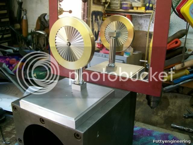
This is a slight diversion from my Loco build but I've been wanting to build a finger engine for some time and kept my eys open for ideas that would add a bit of interest to the build. I saw thread on her where the chap added some engine turning to a horizontal engine that looked real nice this set the little grey cells going. :scratch:. Then on one of my scouting trips to the scrappy I spotted these

100_3492.jpg


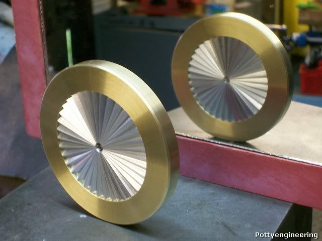
The scrap man saw scrap I saw flywheels.

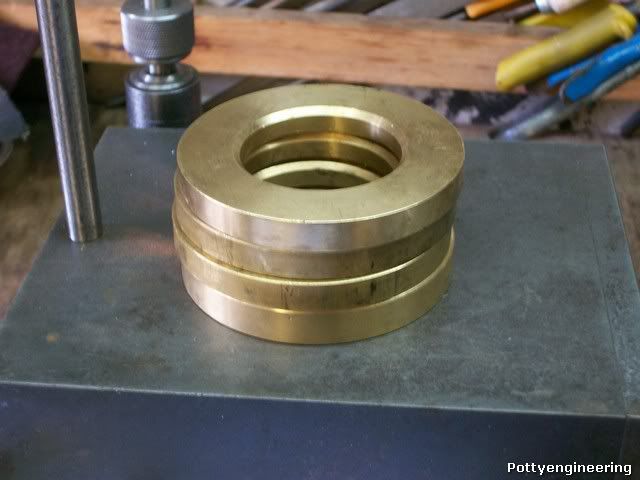
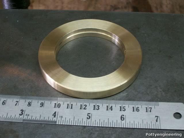
First job clean up one of those discs

100_3493.jpg


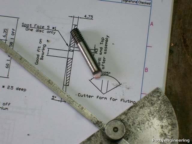
Then grind up a form tool out of a broken cutter, to use as a flycutter.

100_3497.jpg


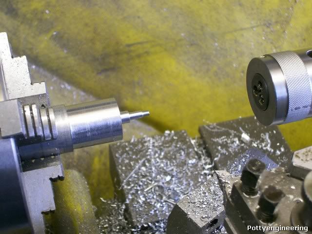
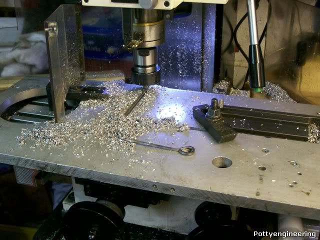
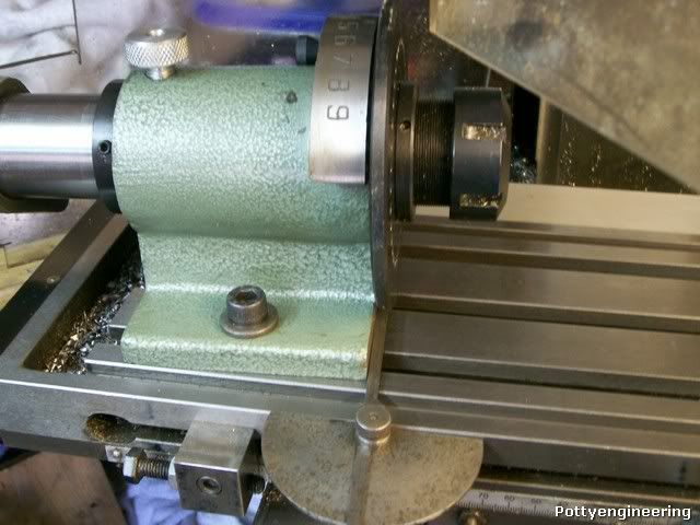
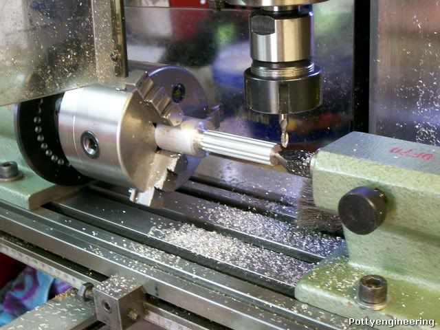
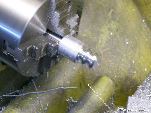
Then set my indexer over 5 deg, and mount a chunk of 2 3/4" dia ally in the chuck, that ally is way too long but I didn't want to cut it down and wast material as I'm planning on using it on another job.

100_3498.jpg


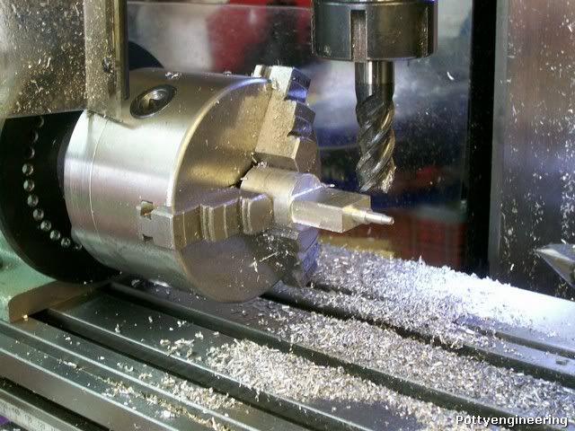
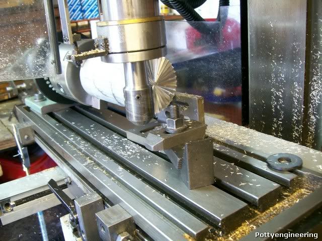
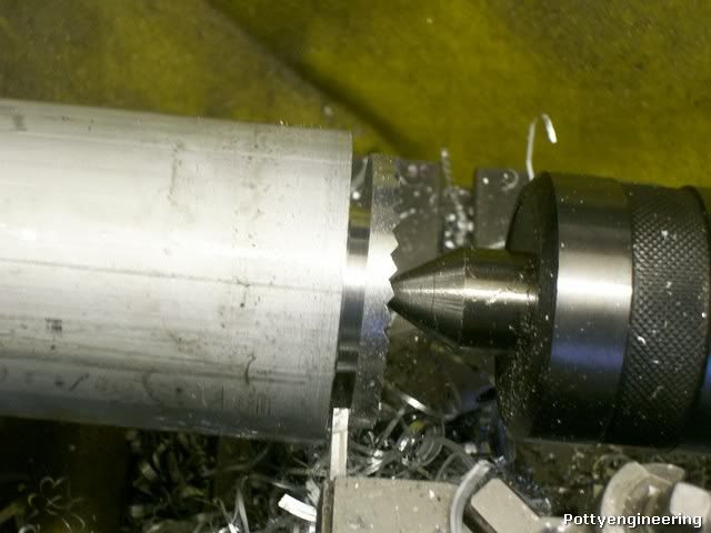
This is the set up for flycutting flutes across the face with that formed flycutter. Th angle plate is to support the bar against the push from the cutter.

100_3500.jpg


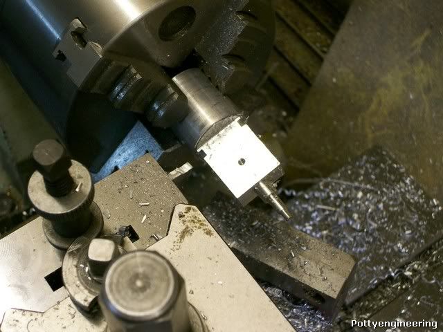
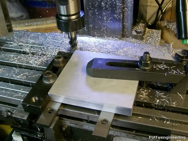
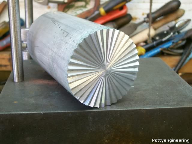
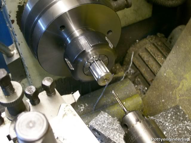
And this is the result 36 flutes across the face of the bar.

100_3502.jpg


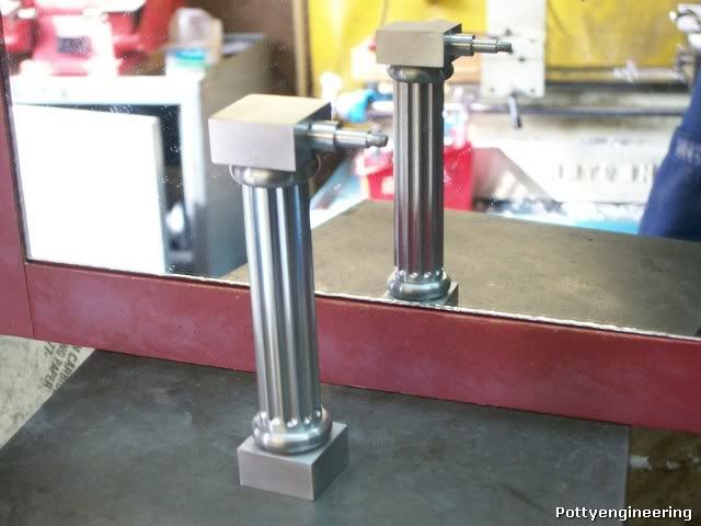
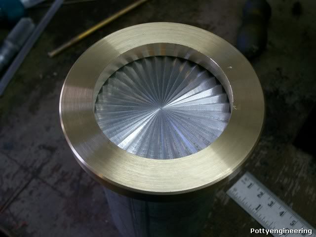
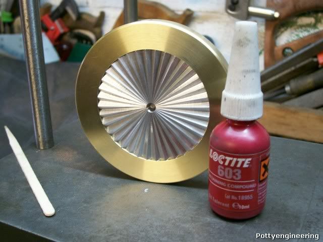
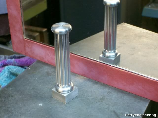
And this is what it will look like as a fly wheel hub.

100_3505.jpg


Have fun

Stew


View attachment Potty Finger Engine Sh1-Model.pdf

View attachment Potty Finger Engine Sht 2-Model.pdf

View attachment Potty Finger Engine Sht 3-Model.pdf

View attachment Potty finger Engine Sht 4-Model.pdf
 
Thanks Zee

Doing that flutting worked out better then I expecting, it just takes quite a while to go the circle (45 min) I did it in two cuts:- 2mm rougher and a 0.25 finisher.

Got a bit more done this morning.

Part off from the bar stock if you tried parting off this thickness in one go you'd end up in trouble, best way is to do it in steps so you keep the groove twice the width of the tool, then for the last bit just adjust the cut so that your bringing the disc to thickness.

100_3508.jpg


And her's the first disc stuck in the rim with high strength loctite.

100_3510.jpg


Looking good :thumbup:

Have fun

Stew

PS added sht 5 of drawing

View attachment Potty Finger Engine Sht 5-Model.pdf
 
Yet another example of the value of this website. A practical demonstration of how to do something that I wouldn't have known where to start.

Thanks
 
doubletop said:
Yet another example of the value of this website. A practical demonstration of how to do something that I wouldn't have known where to start.

Thanks

I'm looking at the setup picture and I still don't know where to start. :big: Of course, I'm still a skeeter winger...

-T
 
Finished off the disc for the other side, and loctited it in position.

One bit of kit I've found very handy especially for getting things clean for gluing etc is one of those elcheapo ultrasonic cleaners, I use it far more than I thought I would.

100_3511.jpg


And here's both side of the fly wheel, I've got to bore it out for the bearing but I'm still waiting for them to come in from Hong Kong, and drill and tap for the crank pin.

100_3515.jpg


That seems to have worked out great.

Cheers

Stew
 
SBWHART said:
And here's both side of the fly wheel, I've got to bore it out for the bearing but I'm still waiting for them to come in from Hong Kong, and drill and tap for the crank pin.
That seems to have worked out great.
Cheers
Stew
Stew,
Your flywheels look awesome. I may have to try and steal your idea for my next build. I'll be watching your build closely.
SAM
 
Stew, for a second there.....I though you where making turbine blades. Nice idea, looks great!

Tony
 
Sam/Tony thanks for your kind comments

Tony:- I guess it will look like a turbine when its spinning, never thought of that,

Cheers

Stew
 
More progress this time on the columb, turned a length of ally down to 15mm diameter than transfered it over to the mill and in the indexer with a 3/16 ball ended slot drill put 12 flutes up it.

100_3516.jpg


Then gripping it lightly in a collet face, drilled and tap both ends M3

100_3528.jpg


Milled a little square base up:- sorry no pics.

Then in the lathe by eye shaped up the roundels drilled 3mm and part off.

100_3524.jpg


And this is what the columb will look like.

100_3526.jpg


I want the engine to look like the Temple of Afinger the Greak Godess of Engines :)

Have fun

Stew
 

A bit off topic

Good crop of frog spawn this year.

100_3530.jpg


OK Stole a few more shop hours and got stuck into the the columb cap.

First op on the lathe.

100_3532.jpg


Then onto the indexer for milling the flats, and drilling and tapping M3 blind

100_3534.jpg


Then back onto the lathe to part off

100_3535.jpg


A quick clean up and a polish, and this is where it fits

100_3536.jpg


Cheers

Stew
 
Coming along very nicely Stew. I hope to see it in the flesh soon.

I don't suppose this one will need any magic dust, it looks magic as it is.

While rooting about today, I found an old sketch I did, for working out the conrod and finger treadle length on an horizontal finger engine. I suppose it could also be used for a vertical one such as yours, using a flat treadle rather than a right angled one.

The dimensions are rather critical for getting a good free running working engine with no mechanical locking up, and I hope you don't mind, but I will pop it in here as this is the only current finger engine build.

John


finger twiddler.jpg
 
Thanks John no problem at all

I remembered you saying the lengths were critical, so I kept the lengths the same as in the NAMES engine I've based it on, so I hope I don,t have any problems, if I do I'll bring it round to the master.

Working in a design office I learnt the hard way the importance of recognising critical features.

Cheers

Stew
 
Good going Stew; some very interesting techniques. I filed those for future reference!

John thank you as well; that drawing with the ratios will come in very handy. I have to make some "paper weights" as gifts soon.

Kind regards, Arnold
 
Nice looking column, Stew. You do nice work, Mister.

Dean
 
That's beautiful work.

And thanks for the happy news about frog spawn. First sign you know.
 
Thanks Guys

Zee yep frog spawn is a first sign of spring, saw my first Swallow of the year last week also so I think summer is finally on its way.

Hacked the base out today from some ally jig plate.

100_3537.jpg


Then squared it up and mill around the edge with a 1/4" ball slot drill.

100_3538.jpg


The roller bearing arrived to day from Hong Cong £6.50 for 10 including postage:- don't know how they do it :scratch:

So that I can fit in the crank pin they are only 7mm dia by 2.5 thick I was planning to assy 2 to the shaft but ended up assembling 3

Her's the assembly so far.

100_3541.jpg


IIt runs nice and free, but with a slight wobble I intended to drill the fly wheel for the bearing with the next size down letter drill so that the bearing were a tight fit but when It came to do the job I forgot and ended up sticking a 7mm :bang: drill through it resulting in a slack fit from the bearing so I had to glue them in place, that where the wobble came from I think.

And I'm not quite sure about the proportions of the base I may hack a bit more off it,

Have fun

Stew

 
SBWHART
Man are you pushing the bling factor up to the Nth degree. I can't wait to see how much more bling you have up your sleeve

Tony
 
Back
Top