You guys are still here?....LOL Okay we'll keep going. It's a little hard to stop when you know you're being watched.
The project cleared a couple of hurdles over the past two days. The rings were turned from the remaining small piece of Durabar cast iron and then I launched off into uncharted waters. Cutting the rings was no big deal. Lots of care was taken to get the dimensions right and the end product was 2 small rings measuring .750 x .0625 with a wall thickness of .0312. That is 1/32 of an inch for those who are still getting used to decimals. The darned things even felt fragile.
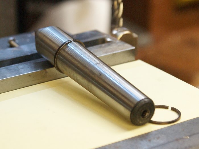
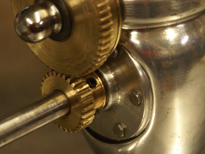
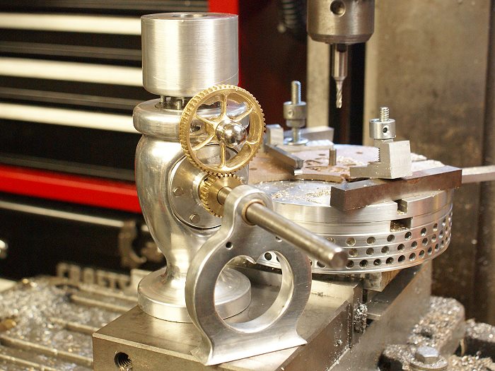
Now.... the rings had to be split. Thank the gods for good advice from a local friend and machinist who builds IC engines. On my recent visit, he showed me a couple of tricks I didn't know I needed. One was the easy way to split a cast iron ring that looks like it would fall part under any sort of stress. The photo below shows how the the ring splitting was done. It was slipped over the end of a MT2 taper and then gently struck with a piece of brass. It split cleanly and happened so fast that at first I thought the piece had broken.
The photos were taken after the rings had been completed, so bear with me when you see the gaps are already opened.
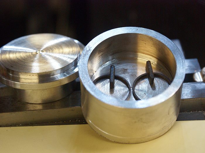
The other trick my friend John shared with me was his method for heat treating the rings to prevent warping or uneven heating. He showed me his little aluminum "can" that he made for just that purpose. The rings needed to be expanded so they will spring against the cylinder walls. This is done by placing a spacer in the gap and then placing the rings inside the "can" and closing the lid. The can was then placed in the kitchen oven at 500° for an hour and then left to cool, unopened. The aluminum spreads the heat evenly and cools the same way, preventing warp and relieving any stress the machining might have induced.
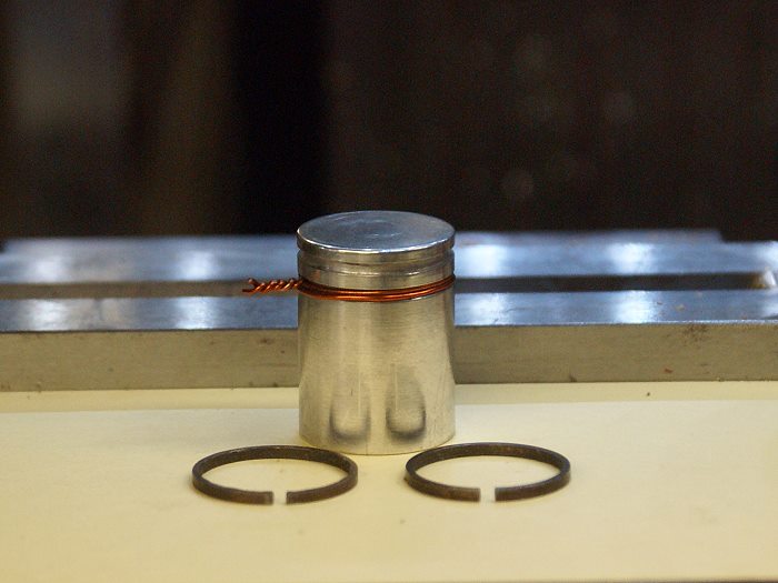
Once the rings were cool, the ends of the gaps were filed to allow the rings to fit within the cylinder bore with .003 left in the gap for what I assume is expansion clearance. The end result was a beautiful fit. The piston was then turned and the grooves were cut to fit the original inner diameter of the rings, plus .001 (who really cuts a .0005 pass on a hobby lathe?) The copper wire in the ring groove is there to keep the piston from disappearing down the cylinder bore while I'm handling it.
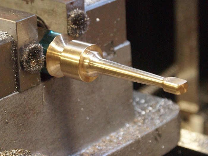
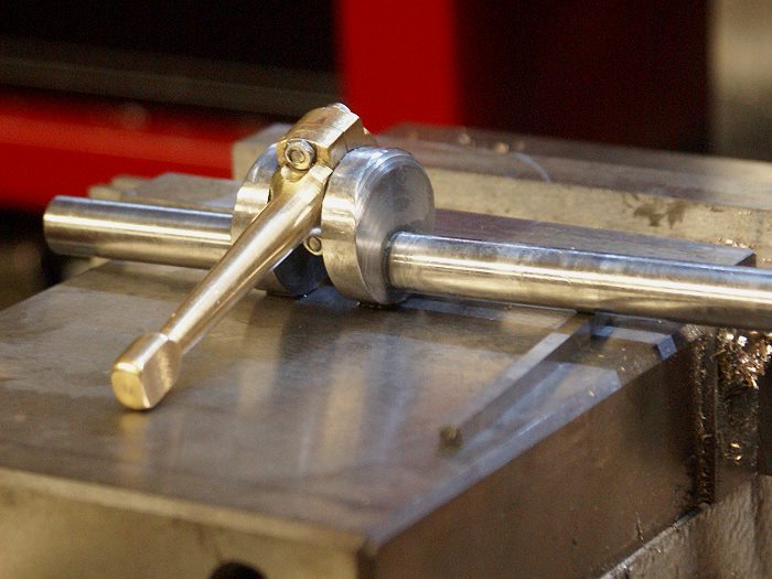
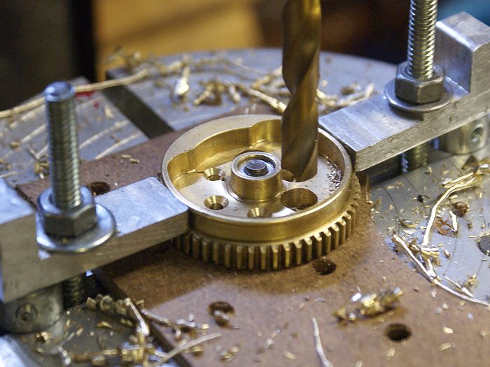
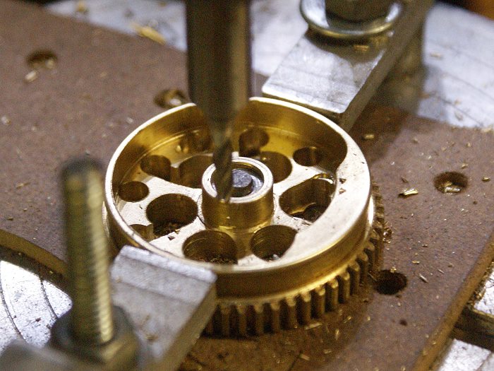
I then moved back to the lathe to turn the basic shape of the modified connecting rod. Once the contour was as I wanted it, the piece was moved to the mill to give it the flat surfaces. Yes.... I know the vice is more stable in the middle and yep... that small end is probably a great place for a machinist jack, but I was only removing .010 per pass for a total take of .0625. No harm, no foul.... and it worked out fine. The big end was still very firmly attached to a nice solid supportive piece of brass hex bar which.
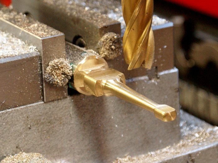
The big end got the same treatment, along cuts for the bolt heads. The piece was then cut off the hex bar before drilling the end cap bolt holes. Brass was chosen for the connecting rod due it's wear properties, since the crank design made installing a bushing impractical.
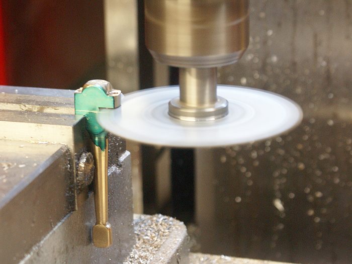
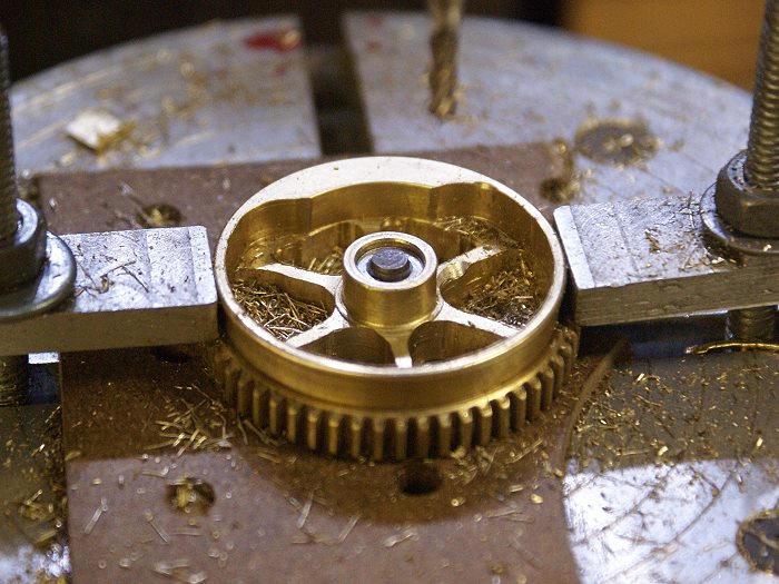
The big end was made longer than its final configuration so it could be cut away. The end cap bolt holes were drilled prior to the separation so things could be cleanly re-mated. My handy dandy carbide saw blade made easy work of the cut. The setup is much more stable then it appears and the blade was introduced slowly and advanced into the cut in quite small increments. A final pass with an end mill put the mating surface to rights and once bolted together, let me drill and ream the journal bearing surface in the proper spot.
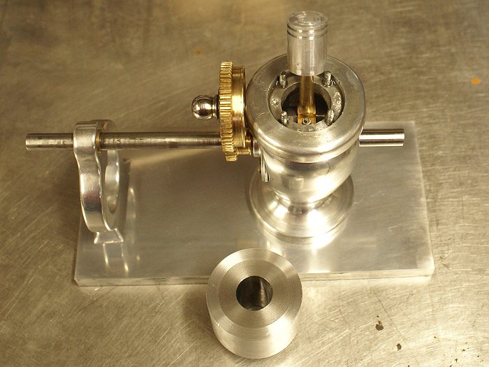
The con rod was then fitted to the crank shaft for a test fit and with a bit of oil, proved to be spot on. Just enough friction to let me know it was a good fit and little enough to allow for an easy lapping fit with a bit of metal polish, just to slick it all up.
Another couple of steps out of the way. The piston and con rod will get some attention tomorrow as the wrist pin is fitted and the crank is tested int he crank case. I'm a wee bit concerned that the modification to the con rod might require some clearance adjustments to the inner bore, but that remains to be seen. Tomorrow should tell more of that story, as some of the assembly process begins in earnest.
Steve