Overcrank Single Cylinder Engine

Home Model Engine Machinist Forum

Help Support Home Model Engine Machinist Forum:

This site may earn a commission from merchant affiliate links, including eBay, Amazon, and others.
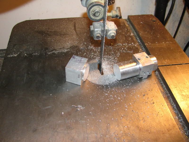
As promised, here is a picture of my "drive dog" by itself.
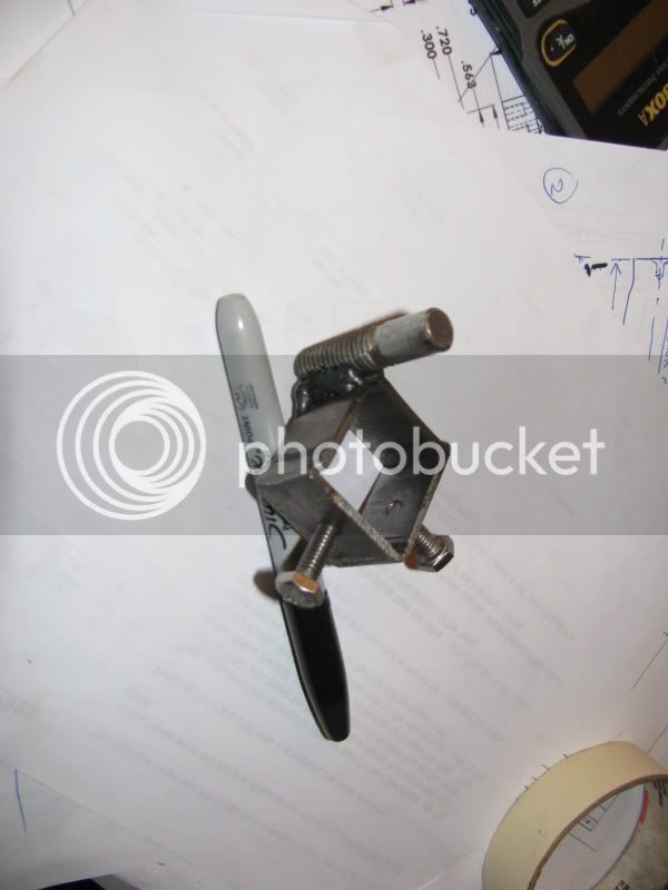
drivedog002.jpg
 
Looks like a great start Brian
Will be following along :)
Pete
 
... as will I, as always. Good to see you gettin; down and dirty again!

There are, however, a couple of points that are puzzling me.

1. Your exhaust port - why that row of tiny little drilled holes tucked between the comparatively huge inlet ports? To my eye that port doesn't look near big enough to pass out the expanded (decompressed) air or steam after its been thru the cylinder.

2. Why didn't you save your self a considerable hunk of metal by starting with the stock for the cylinder just a little over finished length, chucking in 4 jaw to turn the first spigot, face, flip into either 3 or 4 jaw and turn the spigot on the other end? You may very well have a valid reason for going about it the way you did, but it escapes me!
 
Tel---You raise some very valid points. Those are the port and passage sizes used by Elmer Verbourg on his #33 Mill engine. The large slotted ports do nothing really, they simply are a large "target" for the steam passages out to the ends of the cylinder and the inlet passage (which is also .074" dia.) to intersect with. The .074" steam passages out to the ends of the cylinder have a cross sectional area of .037 x .037 inches. x 3.14=.00430 square inches. The .043 holes for the exhaust have a cross sectional area of .0215 x .0215 x 3.14=.00145 sq. inches. If you multiply that .00145 x 3 holes, it=.00435 which is very close to the diametral cross section of the angled passages down to the ends of the cylinders and the single 0.074" dia. air inlet, so I think the total air inlet and exhaust is quite balanced. I think Elmers limiting factor may have been the ammount of flat area he had available on the side of the cylinder for the steam chest to fit.---As to why didn't I use a 4 jaw in order to save some material---i'm a real Wuss at using the 4 jaw!!!! I figured the few cents extra that I spent for material would far outway the frustration that I invariably experience when trying to set up that damned 4 jaw chuck!!! ;D ;D ;D
 
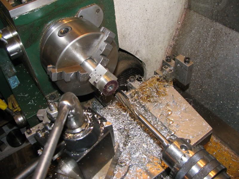
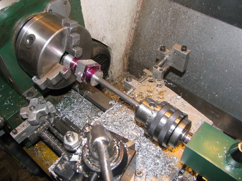
Here is a little tip, for what its worth---as you have seen, in a previous step I drilled and reamed the cylinder to 0.375" in the chuck. The finished bore will actually be 0.625", so why did I do this? Well, because the angled steam holes that run from the ends of the cylinders up 20.22 degrees to the ports in the steamchest area actually have there "start point" almost exactly on the edge of the 5/8" bore. By leaving the bore undersized, this gives me a good solid place to start that .074" dia. drilled passage. So----why did I ream it to 0.375" then?--well that answer comes when I go to put the cylinder back in the lathe chuck.The lathe chuck is only gripping a very short area at the end of the "spare material" so that I can part the cylinder off to length in the final lathe set up, and I don't want the part to set "cocked off" at an angle in the chuck jaws. So---I chuck up a peice of 3/8" dia. cold rolled in my drill chuck and slide the cylinder over it. This ensures that the long axis of the cylinder is truly in line with he center of the chuck. Then I open the chuck jaws to accept the part and slide it into place while it is still supported on the 3/8" rod. I lock down the tailstock, then close the main chuck jaws, then unlock the tailstock from the lathe bed and slide it with the 3/8" rod back out of the way.
settingupcylinchuck001.jpg
 
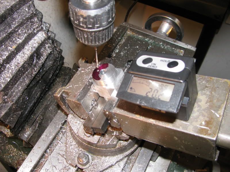
We're almost down to the wire here. As you can see, a new peice of kit has been added, a digital angle meter by Wixey. I really like this one, because it has the flip up screen, that lets you view the readout panel without having to stoop way over or stand on your head to read the numbers. Both of the angled passages came out "dead on" in the correct place.
finalcylmachining002.jpg
 
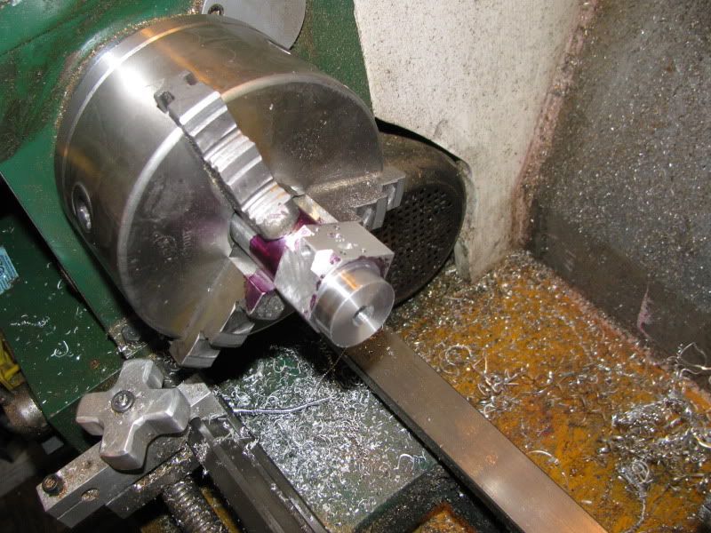
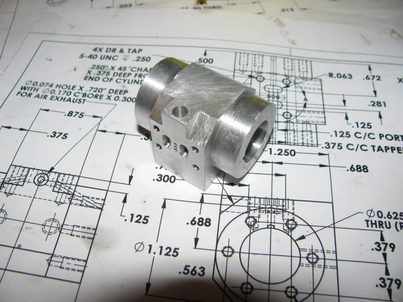
This is the cylinder after it was taken back over to the lathe and drilled/reamed to its finished 0.625" bore. You can see where the ends of the angled holes end up in relationship to the finished 5/8" bore---It would have been impossible to start the drill in the correct place if the 5/8" bore had been put in first. Now for a bit of quality time on the rotary table to get the 6 tapped holes in each end.
almostdonecylinder001.jpg
 
Hi Brian,great work on the cylinder but can I ask why you have made the exhaust port so much smaller than the intake ports?Is this because it will never be ran on steam?Thanks,Crab
 
crab said:
Hi Brian,great work on the cylinder but can I ask why you have made the exhaust port so much smaller than the intake ports?Is this because it will never be ran on steam?Thanks,Crab
Take a closer look at the drawing I posted crab. The exhaust port is .074" dia. You are looking at a 0.170" dia. countebore which the exhaust stack sets into.
 
I was looking at the port face,it looks like you have 3 very small holes for the exhaust.On a steam engine this port should be at least 2X the size of the intake ports.Won't matter on a air engine ;D.
Crab

Sorry,some how I missed Tel's post ::).
 
-i'm a real Wuss at using the 4 jaw!!!! I figured the few cents extra that I spent for material would far outway the frustration that I invariably experience when trying to set up that damned 4 jaw chuck!!!

Time to 'grasp the nettle' matey, mastery of the 4 jaw will repay you the time you spend many fold.

Coming along nicely!
 
Can't do anymore untill tomorrow. I just checked, and my 0.106" tap drill is broken and my #5-#40 and #10-24 taps are both dull and due to be replaced. Once I get this cylinder finished tomorrow, I won't be doing such "in depth" postings on every little bit that I build. Its just that cylinders are kind of a "special animal" and as such rate a bit more explanation for the new-bees out there.
 
Just had a look at the no 33 drawings Brian, and I see what you mean - BUT, to my mind that set up is just wrong. Ol' Elmer was obviously a very clever bloke, but apparently he didn't get everything right!

Even with the separate port plate on, with it's smaller inlet ports, the exhaust looks way out of proportion and I very much doubt that it would work very well, if at all, under steam.


no33 snip.jpg
 
I'm not putting this forward as a shining example of the art of port cutting - but the proportions are much better.

 
Tel---Far be it from me to argue with a man who has actually designed, built, and succsefully ran his own steam engines, while I have never built one!!! However, here is the deal. I am going to post all of the drawings of the engine with ports a'la Elmer Verbourg, which I know will run succesfully on compressed air. If you want to print out the appropriate sheets when I have completed them and mark them up to what you think would run properly on steam, then send them to me by email, I will reissue them in your name for those who want to run this engine on steam. This must include the cylinder, valve body, valve, valve body cover plate, and eccentric drawings, as they will all probably change to accomodate steam passages. I'm quite serious about this. I do respect your abilities, and it would definitly be a big favour to anyone out there who may want to "steam" this engine.----Brian
 
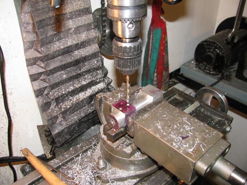
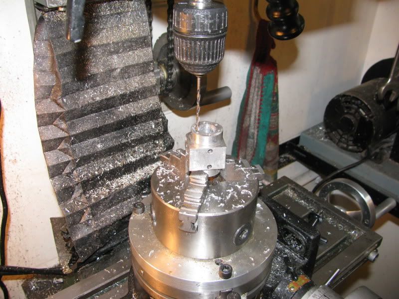
This is the final step in machining of the cylinder. When I built the Elmers #33 a couple of years ago I used co-ordinate dimensions to drill the 6 holes in each end to be tapped for the bolts which hold the inner and outer cylinder heads in place. This time around I elected to set the cylinder up and drill the holes on my rotary table. I'm not sure that one method is preferable over the other, as they both seemed to work out alright. I had one "Oh $hit" while drilling the second end. I used a small c'sink to start all the holes before I drilled them, to keep the drill from wandering. On the second last hole, the HSS tip broke off the c'sink tool in the hole!!!! It wouldn't come out with any of my small picks, so I drilled completely through the cylinder from the other end and was able to tap the broken off peice out. Now I'm off to do a bunch of tapping (18 holes) and if the tapping Gods smile on me the cylinder will be finished.
CYLONROTARYTABLE001.jpg
 

Latest posts

Back
Top