Overcrank Single Cylinder Engine

Home Model Engine Machinist Forum

Help Support Home Model Engine Machinist Forum:

This site may earn a commission from merchant affiliate links, including eBay, Amazon, and others.
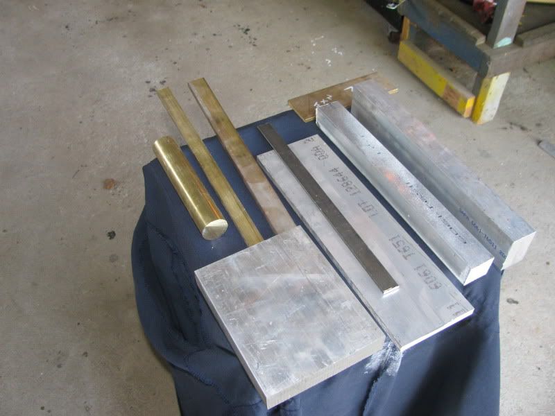
Jerry---Its not critical at all. I just went that size so I could get it out of a piece of 3 1/2" flatbar. Probably 3" dia. would work just as well. If you can wait a bit, I will be posting complete detail drawings on this one and building it. If your machine has a maximum capacity of working 3/8" thick material, then you can run two flywheels, or simply bolt two peices of 3/8" plate together to get the thickness required. If your pockets are deep enough, make the flywheel from brass----Its prettier than steel, weighs the same (actually a bit more) and is soooooo much easier to machine. ---Brian
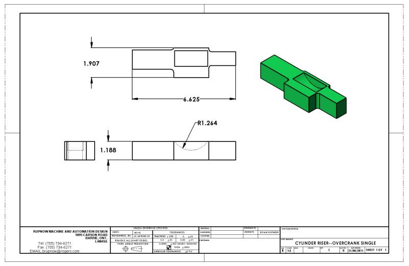
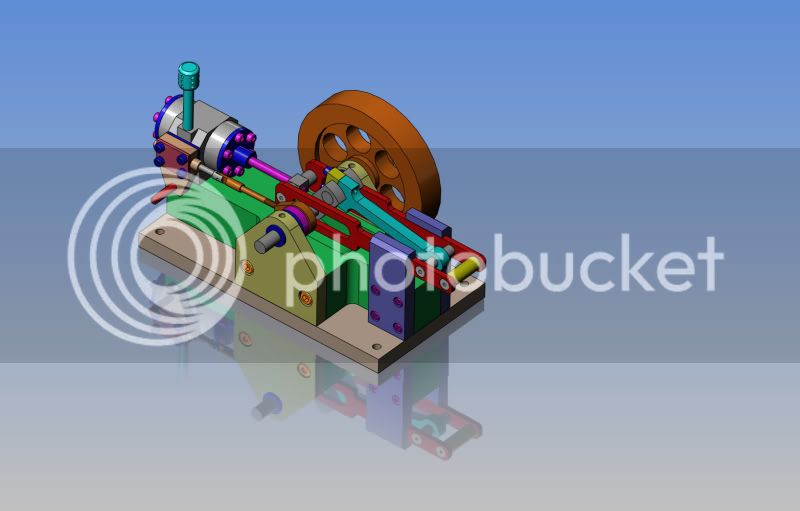
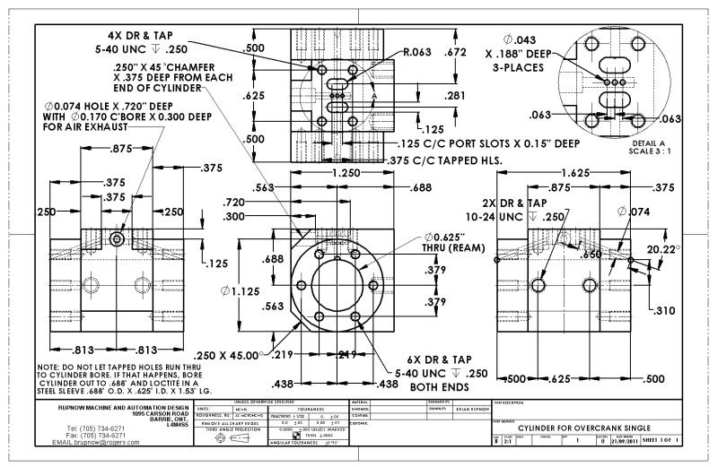
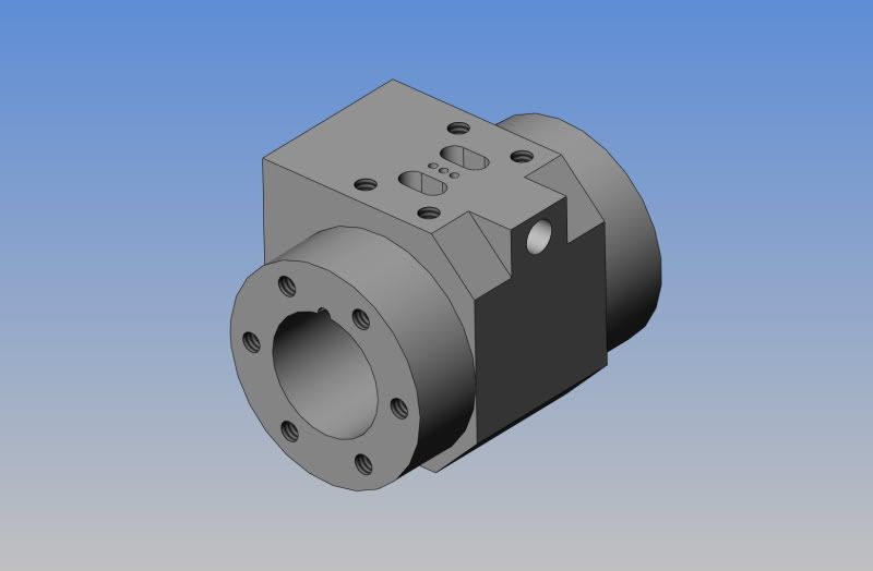
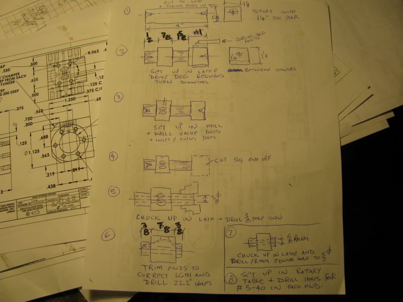
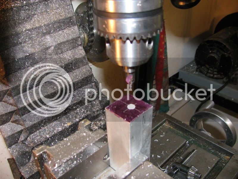
 
Just as a "heads up"---This will be the largest piece of material on this engine. It sets between the main baseplate and the underside of the cylinder and all the other bits. It will be made from aluminum. I will make it all in one peice, simply because I can----I will buy a peice of 1 1/4" x 2" aluminum bar stock. If your mill isn't up to handling a chunk this large, then by all means feel free to make it from a number of smaller peices. Don't bother trying to save this drawing, as it is by no means complete at this stage. I have to add a kazillion tapped holes and clearance holes yet, as I finish all the modelling. There will be a finished drawing when I get to it.----Brian
CYLINDERRISER--OVERCRANKSINGLE.jpg
 
Okay---Now I'm in some trouble, and may need some help. Although my initial plan was to use the exact same valve mechanism and valve hole spacing as I did on the elmers#33 and the same overall valve travel of .050" either side of dead center, keep the same piston thickness, but make the cylinder barrel 1/8" longer at each end to give me 1 1/4" stroke instead of Elmers #33 1" stroke----It seems a bit "fishy" when I rotate the model through its valve cycle. There is something I'm not fully understanding properly. Does anybody out there have a set of plans with this type of valve used on an engine of 1 1/4" stroke. I would be VERY interested in seeing the valve hole spacing and knowing the offset of the eccentric which drives the valve slider to determine the valves full travel. I want to get this right BEFORE I finish the cylinder design and build the cylinder. Any help will be greatly appreciated.----Brian
 
Hi Brian

This is what I use

scan0001-1.jpg


I've used it on a few engines including mu overcrank and it works.

You can cut the ports with standard cutters spaced out to fit then calulate the slide valve to suit.

works for me

You can then draw it out and work out valve travel and the throw for the eccentric.

Stew


Stew
 
Thanks Stew---It seems that I was writing an email to you at the same time you were posting the information. I will study on it a bit now and see if I can understand it.---does A or B have any relationship at all to the stroke of the cylinder and/or the thicknes of the piston? I can see how you arrive at the "throw" of the eccentric based on the travel required for the valve slider.---Brian
 
Hi Brian

A and B are not linked to the cylinder, you can use any size you want, and any size of port openings but its usual to make the exhaust about 50% bigger than the inlet, I just use the nearest standard milling cutters.

Edit= this is only correct for air running,

For steam C= D/10, Exhaust width is D/4, web between ports = C and width of ports
is between D*.75 and D*.875

Where D = cylinder dia

If you look at my drawings for my over crank (sht 6) I have a little drawing down the bottom titled valve geometry that shows how to draw out the valve to give you travel and ecentric throw


Throws half the travel.

I've just done one for the popcorn engine I'm working on.

Hope that helps

Stew

 
My real work has been interfering in a big way with this project today. It never fails---I set around with no work untill boredom forces me to start an engine project, and as soon as the engine project starts to get interesting, the damn phone starts to ring with customers wanting THEIR machines designed. However, I got my very first old age and Canada pension cheques this month, and the $1460 a month from them isn't going to support me in the lavish (choke choke) lifestyle I am accustomed to, so I guess I won't turn anybody away. ;D ;D----As far as the valve porting is concerned---The porting on the Elmers #33 that I built works just fine. The new cylinder is only 1/8" longer at each end than the Elmers #33, so as long as the porting, valve, and eccentric stay the same, and the air travels to the end of the cylinder same as before, it should be fine the way I have it. I will build the cylinder and valves and piston/rod assembly first so that I can manually shift the valve and convince myself that it works okay. thanks Stew, for your help. Now---back to work work work---
 
GENTLEMEN----We are ready to ROCK!!!! I squeezed out an hour at the end of my day to complete the model and I think it looks great!!! Tomorrow I will root through my pile of aluminum bits and see if I have a peice to start the cylinder. I will create detail drawings and post them as I progress, but my advice is that you don't copy them right yet, because this is a "prototype" and the drawings may change as I get deeper into it. I will post a download for all of the updated drawings at the end of this game, when I have this engine running.----Brian
OVERCRANKSINGLE--COMPLETE.jpg
 
Looking very neat Brian

I like how you've shaped the base plate with the crank bearings and slide bar bearing as seperate units, very nice indead, this will build up into a fine engine.

Stew
 
That's going to be a nice looking engine, Brian. And I think the 5/8" bore x 1.25" stroke will be a nice size. As usual, the drawings are spectacular. I have CAD envy...

Chuck
 
Well, there's nothing like beginning at the beginning!!! Here we have $92 worth of the material that will be used to build this engine.---It won't all be used----Its just that my metal supplier gets a bit oinky if I go in and buy 3" of this and 7" of that---and I don't really blame him. The majority of what you see here is in one foot lengths. The exception to that is the short peice of 5" x 1" x 6" long aluminum flatbar which was found as an "off-cut" and will be used to make my flywheel. And---a couple of peices af brass are shorter than one foot because that stuff costs like gold, and sells by the linear inch.
RAWMATERIALFOROVERCRANKSINGLE.jpg
 
Thanks Chuck. The modelling does look very impressive, but then again if you had been doing it every day for the last 10 years, you could easily do it too. I am anxious to get started at this engine, but I got a last minute "rush" design job that a compny wants completed over this long weekend. I stole an hour this morning to go see my metal supplier (who closes at noon Saturday) but now I have to spend a few more hours working for money before I can start to work for fun.
 
FINALLY!!! I get to work on my own stuff!!!! Tomorrow morning I will start machining the cylinder. Don't bother to save these preliminary drawings, as they may change before the game is finished. I will post updated and corrected drawings when I know this one runs.---Brian
CYLINDERFOROVERCRANKSINGLE.jpg

CYLINDERFOROVERCRANKSINGLE--MODEL.jpg
 
I don't usually make any sort of step by step plan when I machine somethng, as it is not usually needed. However, there are enough steps in machining a cylinder that if you get the sequence wrong you have to end up scrapping it and starting over. Last night I sat at the kitchen table and worked things through in my head and made sketches as I went along. So----this is the sequence in which I will machine the cylinder. I will have to make a drive dog to suit the 1 1/4" sq. bar, but it will be added to my arsenal of strange fixtures.
LATHEDOGSANDSET-UPS-1002.jpg
 
Determining the order of operations can be a bit tricky. I've painted myself into a corner
on more than one occasion. This looks like a dandy engine and I've also got CAD envy. Even
though I've used CAM for 20 plus years.

Regards,
Mike
 
Those of you who are sharp of eye will have noticed that the dimensions on my hand sketch didn't agree with the detail drawing. I noticed that just in time, so no metal was cut, and I have corrected the sketch and reposted it.
The first step involved today was to cut a peice of the 1 1/4" square aluminum bar to a rough length (in this case 4"), lay out the centers in the ends of the stock, and put in a countersink in each end in my milling machine.
LATHEDOGANDSET-UPS001.jpg
 
The next step was to build a "drive dog" to transfer torque from the chuck to the part when it is held between centers in the lathe. I meant to take a picture of this drive dog before it was mounted, but forgot. I will post a picture of it later----Basically, it is two peices of angle with the toes welded together and a scrap bolt welded to one corner to engage one of the chuck jaws. Before they were welded together I milled out the radius in the inside corners of the angle so the radius wouldn't interfere with the corners of the aluminum bar. It is drilled and tapped for two 1/4" bolts that are used to "snug it up" to the aluminum part. You will also notice that I am not using a live center in the tailstock.--Why----Because my live center is so short and the lathe saddle is so wide, that I can't engage the tool with the end of the part closest to the tailstock. My "work around" for that is to machine the proper angle onto a peice of 5/8" round bar, give it a liberal dose of lithium grease, and mount it in my tailstock chuck.
LATHEDOGSANDSET-UPS-1005.jpg

LATHEDOGSANDSET-UPS-1004.jpg

 
Here we are at completion of the first lathe operation. No magic here---Used a conventional tool to machine the diameter closest to the tailstock. Then used a cut off tool to plunge cut on the far side of the rectangular "lump" left in the middle. I made about 5 plunge cuts side by side, enough to get my conventional cutting tool into the resulting groove, then machined up to the other square bit still captured in my "drive dog". Then put in a reverse ground tool and took a finish cut from left to right, stopping at the rectangular bit left in the middle. I make use of my home made "carriage stops" for repetitive cuts parallel to the lathe bed, and also the ones I have built and installed for the carriage cross feed.
MACHINECYL-1001.jpg
 
One of the things I like about machining (other than making cool things out of lumps of metal) is the thought process and problem solving. I really enjoyed your sketch of order of operations; I think I may start doing that.

Best of luck with that cylinder, looks like a challenge (at least for someone like me)!
 
Wife and I had to take an afternoon "break". I left a sign on the garage door for a roofer who is supposed to be coming to look at shingling my roof. ;D ;D ;D It all became a moot point anyways. As soon as we got out there and comfortable, it started to rain like crazy!!! :'( :'( :'(---Monsoon time in Barrie!!!
winesign001.jpg
 

Latest posts

Back
Top