zeeprogrammer
Well-Known Member
- Joined
- Mar 14, 2009
- Messages
- 3,362
- Reaction score
- 13
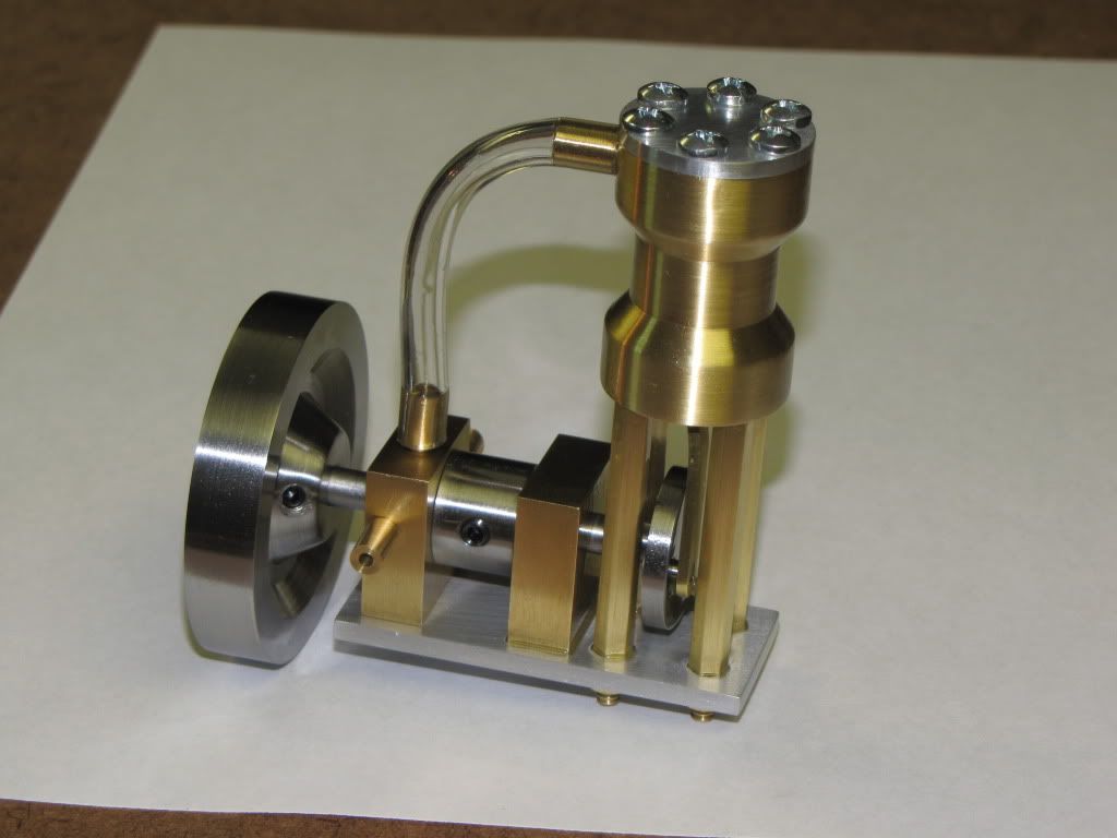
Good news. It's assembled. ")
Sad news. It's not a runner.
There's at least 2 problems with it...
1) I think the piston is a bit too loose and air is getting around it. I may have overdone it when trying to fit. In addition, I suspect the cylinder bore is not true and that may have fooled me a bit. Part of the problem I believe, is that when the holes were made in the ends of the cylinder, particularly for the columns, metal was pushed towards center.
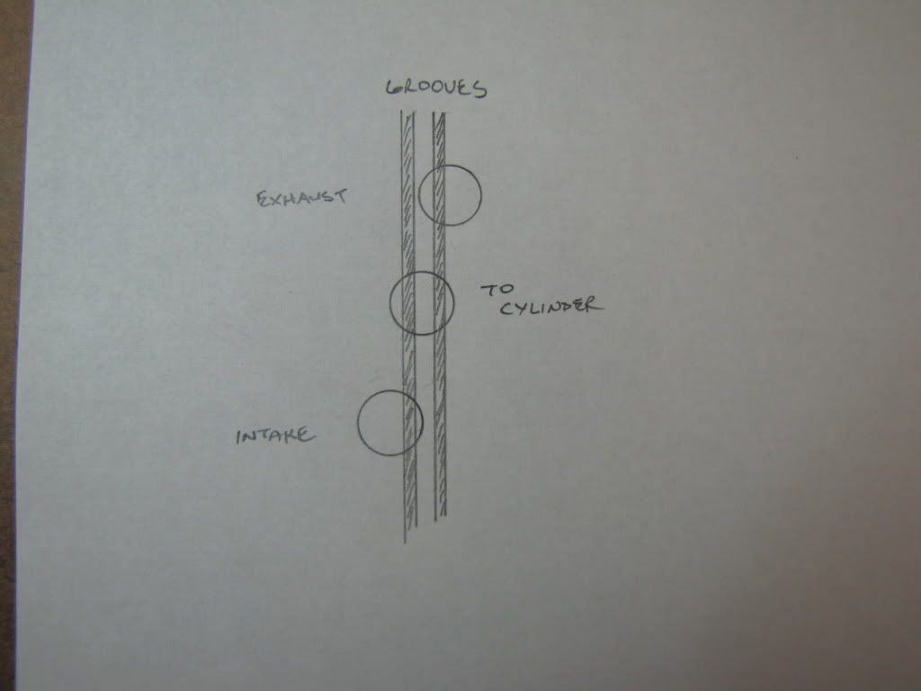
2) The rotary valve has a number of issues with it. For one, it's a tad short so it moves back and forth between the pillow blocks. That makes it difficult to keep the valve grooves aligned. For another, as I mentioned earlier, I think the grooves may be a little off and don't line up with the coupling as well as they could. This is probably minor in that they were fully exposed...just not centered. Third, but I don't know if this is an issue, the ends of the grooves are not cut correctly (as I also mentioned earlier.)
At a minimum, the cylinder will have to be redone. The piston may be okay. The rotary valve? I don't know.
So...do I put this on the shelf and get started with the next engine? If it were just me, for a number of reasons, I probably would. In making it run, will I truly learn something that I otherwise wouldn't? Keep in mind this is just my initial reaction.
I think the 'offset' on the rotary valve can be fixed by slotting the two holes that hold the pillow block. Unless I'm missing something...I think the placement of the grooves is alright too (but I haven't checked all of the ports). Lastly, I doubt the ends of the grooves are critical.
The bigger issue I think, and probably the one easiest to rectify is the cylinder. But I believe I'll find that the piston has to be redone too.
The engine does turn over a few revs but at high pressure. I have a pancake compressor so most likely I lose air too quickly to keep the engine running. I wonder if I should try the air compressor I use for tires etc. It has no storage tank...it just keeps running. If you spin the flywheel by hand...it spins pretty easily. Wouldn't that be a sign of no compression and a bad piston/cylinder fit?
Not a big disappointment mind you. If I do nothing else but put it on a shelf...I'm pretty proud of what I accomplished. And if I don't make it run...there's the next one!
Well I'll sit back and see what the reaction is. :big: (There are examples of this engine around so it's not like it can be particularly interesting to see this one run.)
Robert: Just got your post. Not to worry. As for the grooves...well you can see what I said above. Thanks.
Sad news. It's not a runner.
There's at least 2 problems with it...
1) I think the piston is a bit too loose and air is getting around it. I may have overdone it when trying to fit. In addition, I suspect the cylinder bore is not true and that may have fooled me a bit. Part of the problem I believe, is that when the holes were made in the ends of the cylinder, particularly for the columns, metal was pushed towards center.
2) The rotary valve has a number of issues with it. For one, it's a tad short so it moves back and forth between the pillow blocks. That makes it difficult to keep the valve grooves aligned. For another, as I mentioned earlier, I think the grooves may be a little off and don't line up with the coupling as well as they could. This is probably minor in that they were fully exposed...just not centered. Third, but I don't know if this is an issue, the ends of the grooves are not cut correctly (as I also mentioned earlier.)
At a minimum, the cylinder will have to be redone. The piston may be okay. The rotary valve? I don't know.
So...do I put this on the shelf and get started with the next engine? If it were just me, for a number of reasons, I probably would. In making it run, will I truly learn something that I otherwise wouldn't? Keep in mind this is just my initial reaction.
I think the 'offset' on the rotary valve can be fixed by slotting the two holes that hold the pillow block. Unless I'm missing something...I think the placement of the grooves is alright too (but I haven't checked all of the ports). Lastly, I doubt the ends of the grooves are critical.
The bigger issue I think, and probably the one easiest to rectify is the cylinder. But I believe I'll find that the piston has to be redone too.
The engine does turn over a few revs but at high pressure. I have a pancake compressor so most likely I lose air too quickly to keep the engine running. I wonder if I should try the air compressor I use for tires etc. It has no storage tank...it just keeps running. If you spin the flywheel by hand...it spins pretty easily. Wouldn't that be a sign of no compression and a bad piston/cylinder fit?
Not a big disappointment mind you. If I do nothing else but put it on a shelf...I'm pretty proud of what I accomplished. And if I don't make it run...there's the next one!
Well I'll sit back and see what the reaction is. :big: (There are examples of this engine around so it's not like it can be particularly interesting to see this one run.)
Robert: Just got your post. Not to worry. As for the grooves...well you can see what I said above. Thanks.