Nitro V8

Home Model Engine Machinist Forum

Help Support Home Model Engine Machinist Forum:

This site may earn a commission from merchant affiliate links, including eBay, Amazon, and others.

michaelj199

Active Member
Joined
Aug 27, 2011
Messages
26
Reaction score
13
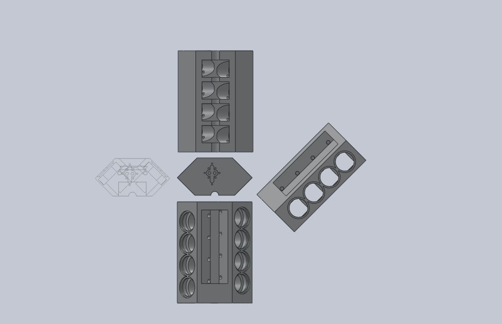
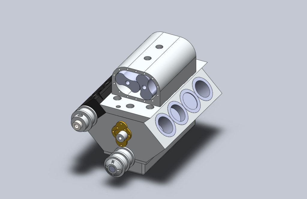
I have been working on designing a V8 two stroke glow engine with a .5in bore and stroke. I plan on starting work on this engine as directed project for collage.
since i don't know much cause I'm just starting out in the machining world, i thought id run it buy you guys for your advice. i know i shouldn't be attempting a V8 but what can i say...

nitrov820.jpg


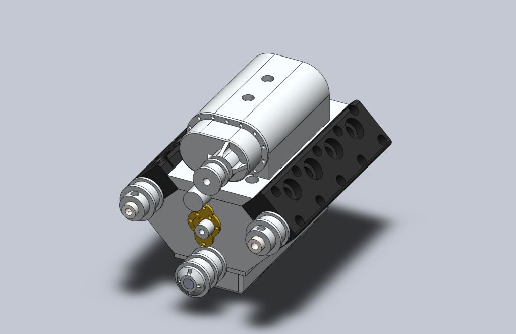
It's a very simple (for the most part) design. I'm not going for pretty I'm hope for running.

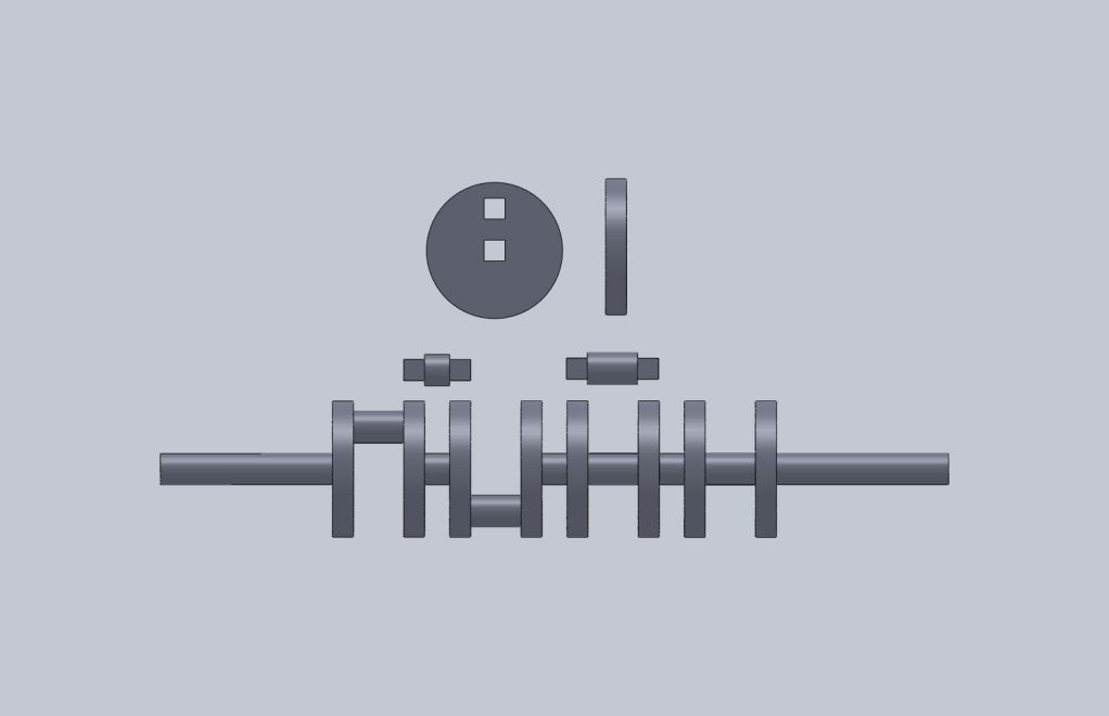
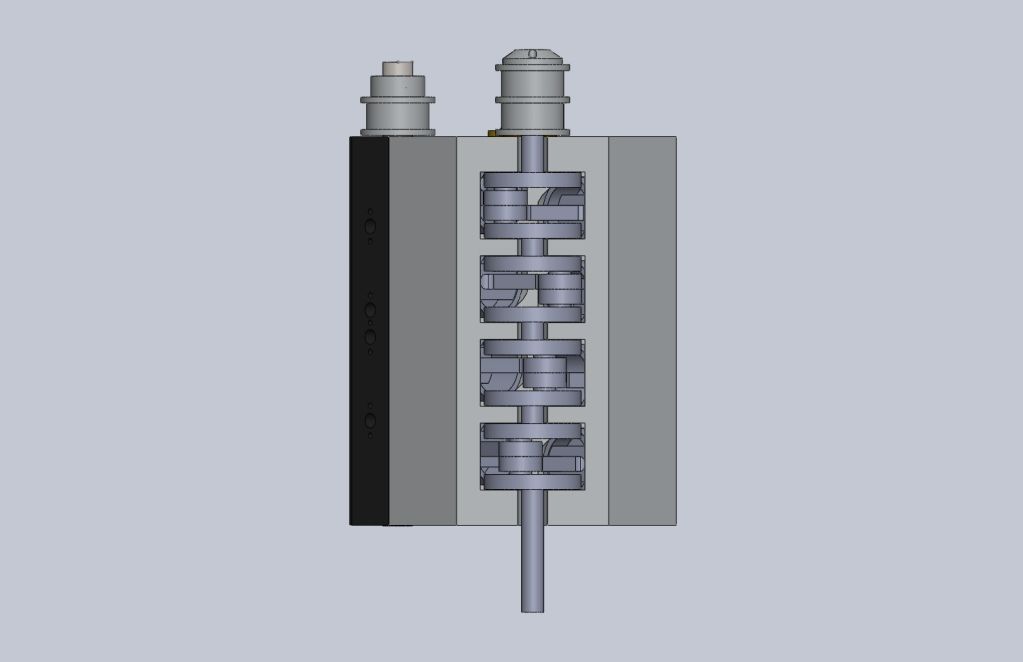
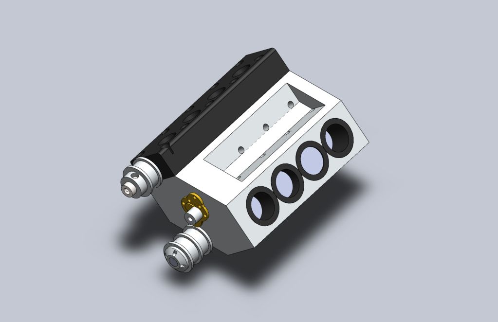
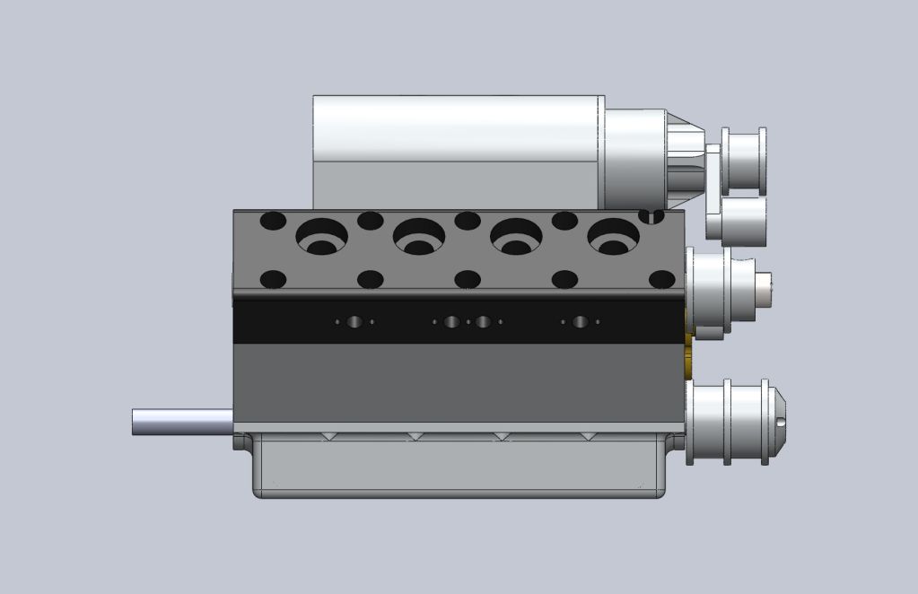
The engine is Two stroke based off a Detroit diesel. therefor a supercharger. im going with a rotary valve setup for "simplicity". the crank is modular steel discs and drill rod held together by square holes.

more details to come...

nitrov820p2.jpg


nitrov820p3.jpg


nitrov820p4.jpg


nitrov820p5.jpg
 
Hi Michael,

well, best of luck with your project. A V8 is quite someting to start off with. Ambitious I would say and however I can totally understand the 'what can I say...' from you (I would be the same ;) ), it maybe would be better to start and learn from a single piston, get this to run and then scale up. A V8 has LOTS of parts (and lots of duplicate parts) so error seeking and correction can be quite frustrating...
On the other hand if you have some guidance which I'm sure you can get around here (and directed project means some guidance on the shop floor as well?) that will be achievable. Just dont lose your motivation between all the parts... ;)

Cheers, Karsten
 
I've done one air motor. also of my own design. also not pretty but ran like a champ. as for duplicate parts and what not, hopefully a lot of it will be CNC as that is what we are focusing on this semester
 
Hi Michael

Pretty ambitious for a first attempt but it looks like a nice design.

I can see those supercharger rotors being a bit tricky though they would definitely be a C.N.C. job. Very awkward shape to do by manual machining.

Nice bit of C.A.D. work BTW what program did you use

Regards Mark
 
all modeling has been on solidworks

so lets start with the block

nitrov820p6.jpg


i figured id mill the water pump hole then mill each deck surface and cut water passages including cross ports. then press in cylinder sleeves and then drill intake holes through block and sleeve. mill the deck surfaces again to insure sleeve flushness. using v-blocks mill the valley then flip it over and mill crank pockets

nitrov820p11.jpg


heads

nitrov820p7.jpg


i figured id use cast iron for its high temp characteristics. im using rotary valves which will get quite hot. drilling the long holes the 3.25in through the head with any precision worries me. the .25in hole is for the rotary valve ( figuring out port size for timing took a lot more then i expected) the .125in hole is for cooling there will be a plug at each end. water will travel along the deck and above the valve (hopefully helping keep it cool). head bolts are 4-40
also if some one can give me the length of the threaded part of a standard glow plug i would be greatfull.
 
valves

nitrov820p12.jpg


the valves are .25in drill rod drilled down the center .125. they rotate at crank speed. the exhaust holes (in and out) are offset for timing and to hopefully limit blow by.

any advise of rotary valves would be appreciated. tolerances and friction limiting. i'm kinda hoping ether there's enough blow by on the compression stroke to get lubrication from fuel/oil or maybe using neolube but i don't know how blow by would effect it.

crank

nitrov820p8.jpg


steel discs with two holes which will be square broached to .125. main bearing and throws will be machined to have square ends. main bearings and connecting rods will be installed before press fitting it all together.
 
I have made a two cylinder air rotary valve motor and the biggest problem I had was the leakage between the cylinders blowing past the rotary valve. Mine was all made on CNC so precision was very good, I sorted mine out by putting O rings on the rotary shaft in between the cylinders. How are you going to drill holes in the drill rod?
 
ok so why i came to my valve design. with some trial and error, math, and a lot of letting it float around in the back of my head i came up with a timing equation.

circumference of rotary valve / 360 * degrees you want the valve open / turning ratio (2 for half crank speed) / 2 = diameter of exhaust port

therefor port size is severely limited. if i went at half crank speed so i could just have a through hole id be limited to .054in exhaust port which is a no go. if i run at crank speed my exhaust port can be .108in which i can live with but requires me to offset my exhaust intake and output of the cam. i tried to figure out a way to drill it at an angle to make a through hole but my cross sectional area was to small and restricted flow. so i came to a tube. off the shelf tubular material can't really be trusted that much for roundness. so i will drill the center out of drill rod with a lathe. half way from one side half from the other. then plug the ends.
 
Hi Michael

Looking at your crankshaft drawing, that's a lot of square holes and press fits. It will be difficult to get them all perfectly accurate and square and should a big end bearing fail they would be difficult to replace. some small motorcycle engines use this type of construction and a big end failure is a technical and expensive job to fix even on a single cylinder engine (I know, I had one !) It will also make assembling the engine hard, sliding all 8 pistons (with rings if you decide to use them) into their cylinders at the same whilst supporting both ends of the crankshaft sounds like a job for your pet octopus.
You might consider split bearings this will make crankshaft construction and engine maintenance much easier. On steam turbines I use plain cast iron bearings running in Silver Steel (Drill Rod) shafts, I know it sounds mad but they run really smoothly and at high speeds ( up to 30,000 R.P.M. in my case) they don't score the shaft and they have a really long life, in fact they can outlive ball races.

I have made a couple of steam engine crankshafts by a similar method. but they were only single throw ones.

What I did was to make the main shaft in one piece initially. fit the webs and crankpin(s) to it a tight wringing fit then silver solder the whole thing together. You could of course cross pin it if the webs are thick enough or I have even heard of high strength loctite being used. Next step is to finish the main journals to size using very fine gentle cuts in the lathe. I then sawed out the bit(s) of main shaft between the webs and again using very fine cuts machine the crankpins by offsetting the job in the lathe by the radius of the crank throw. you can use two distance pieces for this with a centre hole and a hole the size of the main shaft spaced the crank throw away in your case they will be a sort of crucifix or disc as your crankpins are at 90 Deg to each other.

It might also be possible to use this offset turning method to machine the entire thing out of solid indeed full size crankshafts are usually made this way but of course they are usually made from forgings rather than solid billets.

With a 4 Axis C.N.C. this sort of offset machining could be quite easily accomplished. I am as much a beginner as you with C.N.C.
But I think If you were to mount the job in the 4th (Rotary) axis rotate it slowly and arrange for Y and Z axis to describe a circular path around the crankpin centre .reduce the size of the circle on successive cuts. small endmill in the spindle and voila instant crankpins. Well that's the theory anyway something for you to think about.

Regards Mark
 
cast iron bearings... interesting. that would solve a worry i had about using sintered bronze and the the worry about my rotary valves. id like more info on how you prepared these bearings please.

my multi piece crank was for ease of making but i do worry about its strength. if i one piece it my connecting rods will need end caps. end caps need screws so i would need to widen my connecting rods to around .140 to allow for clearance foe 2-56 socket head cap screws. which would mean id need to widen the offset of my block... grr and hope there's enough clearance for them spinning around down below.

the multi piece is made of drill rod which is good steel and a nice surface for bearings. i was going to make a jig for punching the square holes so they would all be the same. but then again this is roughly 1/8th scale and normal main bearings are around 2-2.5in which would be .25 to .3125 and they are currently .1875.

a lot to think about...
 
If you want those square holes to all be true and accurate then get them spark erroded, if you have CNC at your college then I would assume you also have EDM. Punching will distort the webs too much.

J
 
its a small collage. our edm is cobbled together just big enough for tap removal it would take a day per hole. the broach i have works basically works by pushing a tapered square file through a pre drilled hole hopefully this wont distort the web to much

as for a one piece crank i didn't leave enough room for two piece connecting rods.
 
Hi Michael,
when it comes to a built crankshaft I find the Schillings-approach quite an interesting idea. Needs some space for the bearings though. But maybe woth considering.
Have a look here- the text is in german, but I think the pictures say enough.

http://www.cncmarc.ch/reihenmotor.htm

Cheers, Karsten
 
wow that's a really cool crank design. with how compact this engine design is i can't impalement anything like that but that's definitely something to store away for later pondering.
 
piston and connecting rod

nitrov820p9-1.jpg


i am using piston rings and unless 0-80 screws will hold the connecting rod end caps on i see no way to make two piece connecting rods that will fit in my block.
i modeled using 2-56 screws but the connecting rod would hit the bock and opposite side piston sleeve. i know it will be a pain to install but i see now way around the trade offs for making such a small engine. i mean it's 3.25in long.
i hope you guys are not saying my crank is doomed to fail cause i don't really know how to fix it without a complete engine redesign.

and the the supercharger

nitrov820p10.jpg


the vanes i tried to make like the real thing. to model this i had to draw 4 equation lines using equations for an epicycloid and a hypocycloid. then spline them together and extrude it. this will be cut top down using CNC. the case is fairly straight forward but is going to be a nightmare to set up. i have not made the rear bearing case but the front one includes the gears.

the pulleys for running everything are going to be .080" (MXL) timing belts from SDP/SI. the belts are 3/16th inch wide.
 
Hi Michael,

Very interesting your project... and the design is very good !!!

th_wwp please!!!

Cheers,

Alexandre
 
My engine will have two carbs and Steve Huck has graciously allowed me to use his carb design from the Demon V8. Now the Question is carb sizing and whether or not to offset them in a way so the second carb acts like a secondary. would that allow me to more easily control mid range air/fuel ratio or would it just add headache? i want this to be high revving and id like to but a load on it... maybe one day put it in an 1/8th scale pickup. ;D
 
Cast iron bearings can be made just like bronze shell bearings. porous bronze is the ideal material for high load low speed bearings but at high speeds a peculiar effect sets in which I have seen in practice. They tend to score the shafts even very hard well lubricated ones. In fact they don't just score them they can actually eat them away in no time. The idea is that the bronze being softer wears before the hard steel and when it does you simply adjust the bearing (thinner shim) or replace the bronze bush.

At high speeds like 10,000 R.P.M+ (Depending on the bearing design) the exact opposite occurs. It is quite a well known effect (ask any maintenance engineer) but exactly why I don't know.

Cast iron bearings don't do this, it is something to do with the free graphite particles in the iron forming a surface barrier. I came across this when I built my first model steam turbine and was having exactly this problem. I was discussing it with various model engineers and had a chance conversation with somone who used to work for Maclaren. According to him they were using C.I. big end bushes in full size racing engines. He probably shouldn't have told me but it was some time ago

As your little V8 is likely to be very much in the high speed category cast iron bearings sound worth a try. I know it sounds bonkers, I didn't believe at first but they work great.

As for your Crankshaft would it be possible to simply make the crankpins a little longer and the webs slightly thinner to make room for the bolts and you could fit studs to the bearing caps and nuts on the inside of the conrod end. this would leave you a litlle more room in the crankcase. without needing to alter your cylinder centres.

I like you idea of a an R/C pickup truck with a proper V8 in it cool or what !

Regards Mark
 
Hi Michael,
when it comes to a built crankshaft I find the Schillings-approach quite an interesting idea. Needs some space for the bearings though. But maybe woth considering.
Have a look here- the text is in german, but I think the pictures say enough.

http://www.cncmarc.ch/reihenmotor.htm

Cheers, Karsten

Yes interesting it looks like the crankwebs are split and the inner bearing race actually forms part of them It has several advantages

It would be very rigid

The bearing load would be reduced as they are bigger, although the linear speed would increase for a given R.P.M.

It would be easier to machine (no square holes)

It would not need a major redesign just an enlargement of the main bearing seats.

Regards Mark
 
Regarding your question about Glow plugs, the length of thread on a OS #8 plug is 4.5mm (0.177") and the thread is 1/4x32 UNEF.

Looking at your piston drawings do you think rings are really needed? Steel liners and CI pistons are quite common on Glow and diesel engines. I've just finished a glow motor with the plain CI piston lapped to the liner and thats good for 10,000rpm with a 10x6 prop

[ame]http://youtu.be/AvbnjyrHq8M[/ame]

J
 
Back
Top