Need Stuart No. 4 Help Please!

Home Model Engine Machinist Forum

Help Support Home Model Engine Machinist Forum:

This site may earn a commission from merchant affiliate links, including eBay, Amazon, and others.
C

chiliviking

Guest
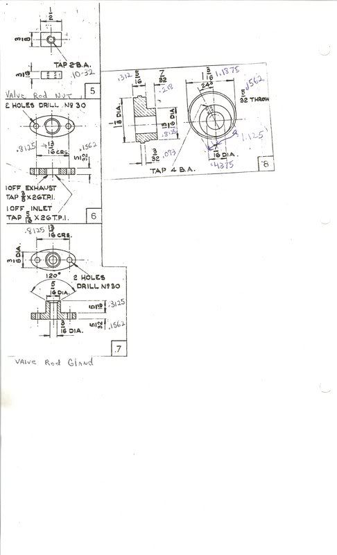
Has anyonebuilt a Stuart No. recently that could give some assistance? I find the print for the eccentric quite ambiguos and have some questions. Someone who has built one recently and has access to the plans would be most helpful. I really don't want to guess at their intentions and ruin the part.
 
can you scan or photograph the offending bit? I'd bet many here can help interpret the plan for you even if they haven't built a 4a,

ST does love minimization. If there's a dimension on a plan that you can arrived at by doing 138 calculations, you can be the draftsman will have omitted it figuring 'let the builder worry about it". perhaps this is considered correct, i find it annoying. Love their castings, hate their drawings.
 
I will try to get my scanned image posted so folks can tell what I'm talking about. Never posted a scan before but I guess it needs to first be uploaded to photbucket or similar first.
 
eccentricprint.jpg


I will post this first to see if it is of a size that can be read then if all is well I will post my questions.
 
The drawing looks straightforward enough to me - let us have your questions.
 
1. I really don't understand the sinifigance of the 24 degree tilt on the drawing unless it has someting to do with the timing of the engine. Would the offset on the eccentric not be measured along the line depicted as the 24 deg. offset as opposed to measuring along the vertical lines depicted as crosshairs on the drawing which would cause the max lift to be greater than the offset specified?

2. When it says 5/32 "Throw" I assume it means that the center of the crankshaft bore is offset from the center of the eccentric which would result in 5/16 movement at the valve. Or do they imply 5/64 offset to provide 5/32 at the valve?
 
I'm not quite sure about that 24° either. It appears to be the high point of the eccentric lobe, with the pinch screw located on the same line. I'd make it to that, ignoring the 'cross hair' lines. Setting the valve can be done later, by the usual method.

I'd read that offset as 5/32", giving the total valve travel of 5/16", as you assumed. A quick check on your steam chest/valve dimensions should confirm this (or make it blaringly obvious that we are both wrong ;) )
 
Yeah unless I get some input to the contrary I Intend to proceed that way. The high point of the cam is definiately along the 24 degree line and it just seems logical that the offset would be figured along that plane. I will remove the steamchest cover and look at what 5/16 movement on the steam valve does as far as covering and uncovering the ports and it should be pretty obvious. It just never hurts to get second opinions sometimes and the folks on this board are so great with help. Thanks for the input.
 
Do you think the 24 degrees relates to the position of the grub screw in relation to the eccentric?
 
I think the draftsman cribed part of the drawing from the reversing gear drawing and did not readjust it???
 
JaguarB said:
I think the draftsman cribed part of the drawing from the reversing gear drawing and did not readjust it???

I also think so. The fact is, that if you build a stephenson reversing gear, the two eccentrics need an offset. And this seems to be 24°. (sounds quite realistic). If you want to know why the offset, i can explain.

Florian
 
i think Jaguar nailed it, still those Stuart plans have been around forever and day, you'd think they'd have cleaned them up....it just makes no sense to me to talk about an angular relationship of two circles but it would be a requirement with a second eccentric for reversing gear. Me, I'd go ahead and make it assuming its an error, or if its really bugging you email Stuart - there's a link on the web site
http://www.stuartmodels.com/
 
I don't have the whole picture but would the 24o angle mean the grub screw is located in a position where you can get to tighten it up without resorting to hiring a contortionist ;) ...................... just a thought 8)

CC
 
I looked at the non-dimensioned drawing of the accessory reversing gear on the Stuart web site and it appears that the 24 degrees is the eccentric setting angle from horizontal when the engine is at top or bottom dead center. I printed it out and drew a couple of lines and measured them at 25 degrees which is certainly within my limits of drawing lines. This would have no impact on making the part. Also, scaling the drawing (bad practice) confirms that 5/32 is the offset from the center of the eccentric to the center of rotation. This gives 5/16 of travel of the eccentric strap.

Drawing is at:
http://www.stuartmodels.com/images/access/34-50-71158lg.jpg

Gail in NM,USA
 
Thanks so much for the replies , I feel more confident In proceeding as I had planned. Due to my health I haven't had much shop time lately but I did get out yesterday and machine the rod journal on the crankshaft with a cutoff tool wit one end ground like a left hand tool and theopposite end ground like a right hand tool. With patience it worked out fine but one had to be very careful or it had a tendency to dig in. I undershot the dimension slightly but a light sanding of the rod cap closed it up to a nice fit.
 
It's called the "Angle of Advance"

An engine without valve lap would have eccentrics at right angles to the crank throw. With lap you must advance the eccentric by the amount of the steam lap, in this case ( with out looking at the rest of the drawings...mind you)it's 24 degrees.

It's typically 30 degrees or so depending on who layed it out.

Most small an model engines have steam lap but no exhaust lap. :)

Dave
 
Dave, that makes sense, so they're telling you 24 degrees as to what position its clamped onto the crank in as opposed to anything relating to the machining of the part
 

Latest posts

Back
Top