- Joined
- Oct 28, 2009
- Messages
- 58
- Reaction score
- 36
In 1997, I ordered the plans and kit for the MLA Diesel from Andy Lofquist, knowing that it would be some time before I would get around to building it. Well, that time is NOW.
I plan to make three of the diesels. One to fasten to my workbench. The second to give to my brother-in-law. He lives in southern California, and is big into model airplanes - primarily R/C sailplanes and Old-Timer style free flight. It would be cool to see one of my engines take to the air - and he's the man who can make it happen. Perhaps the third one will take to the air here in Salt Lake City.
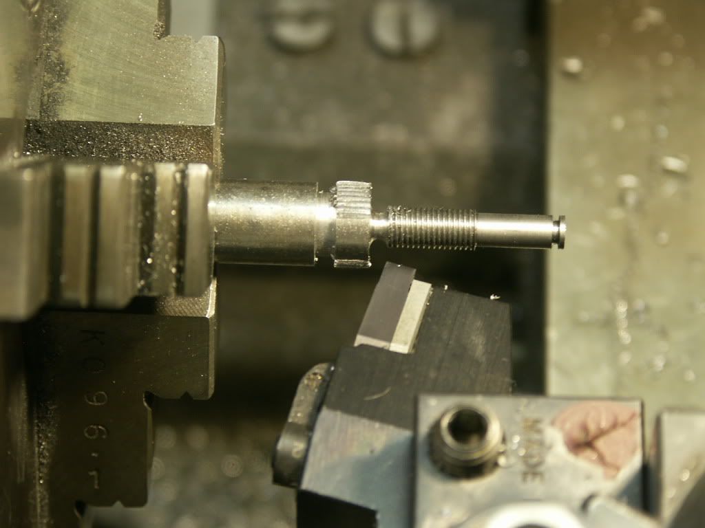
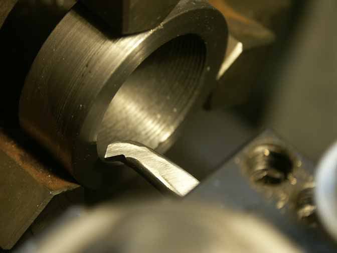
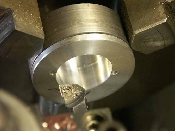
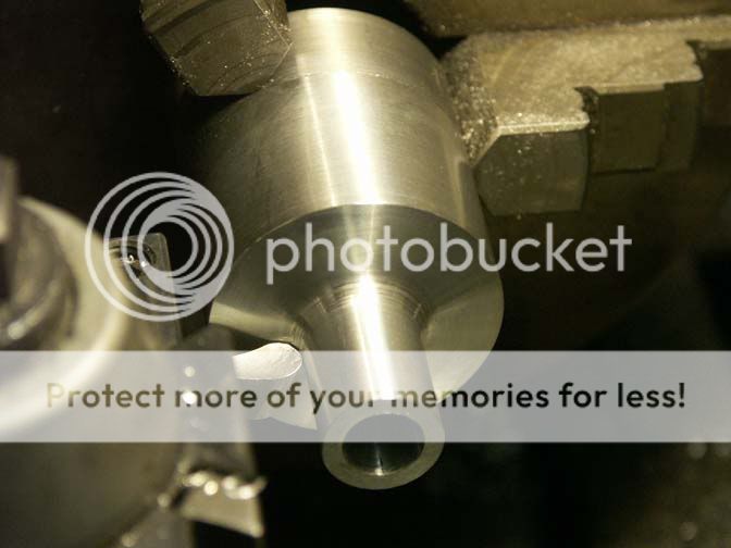
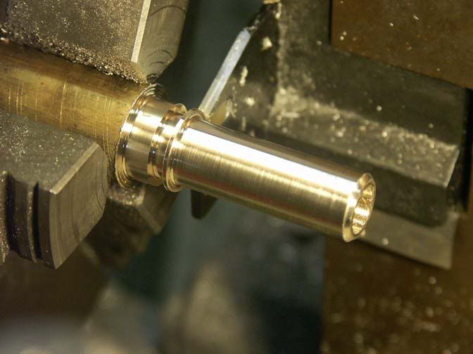
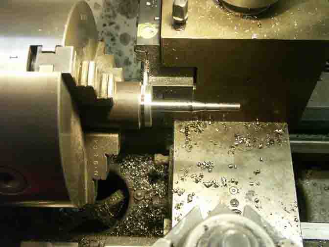
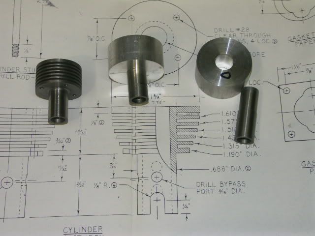
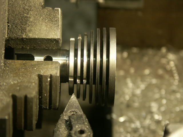
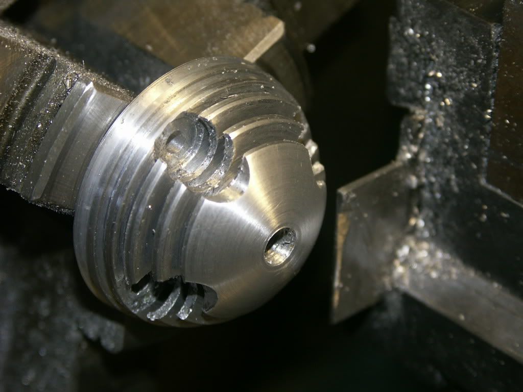
In this photo, I've just finished turning and grooving the first engine cylinder for the "MLA Diesel".
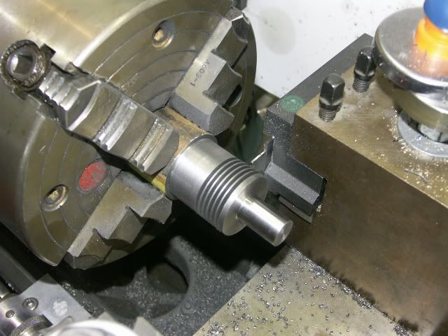
The cylinder is cast iron, and rather heavy. It alone weighs 4.6 oz. (130 gm). About 10% of the material will be removed in subsequent machining, but it will still be about 4 oz. when completed. I haven't weighed the "Mate" diesel I just recently completed, but the drawings say it weighs 150 gm - in total. I'm guessing now that this engine will weigh about 12 oz - without a propeller. I am starting to make efforts to reduce the weight as much as practical.
The grooves are .063" wide and .445" deep. Since I have a tool block holding 1.25" indexable partoff blades on the back side of the cross-slide, I made a groover by machining a broken Iscar blade. They are made from something like 4140, but it worked great for the aluminum and cast iron fins.
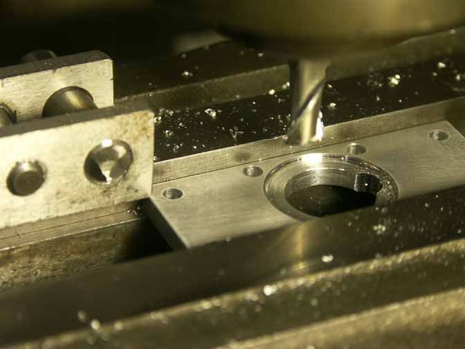
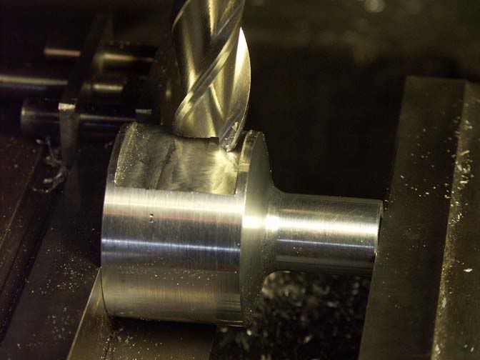
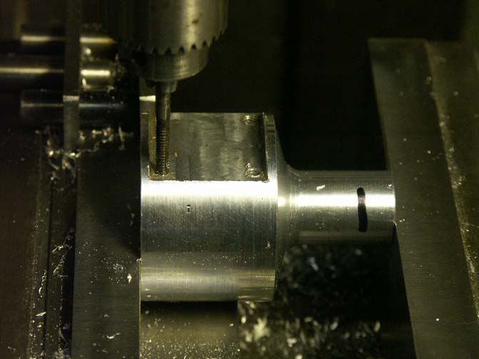
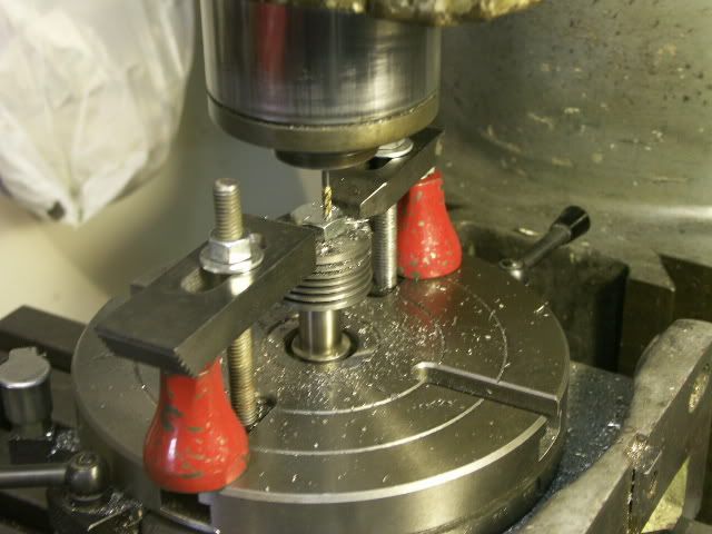
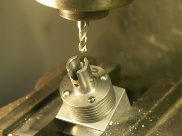
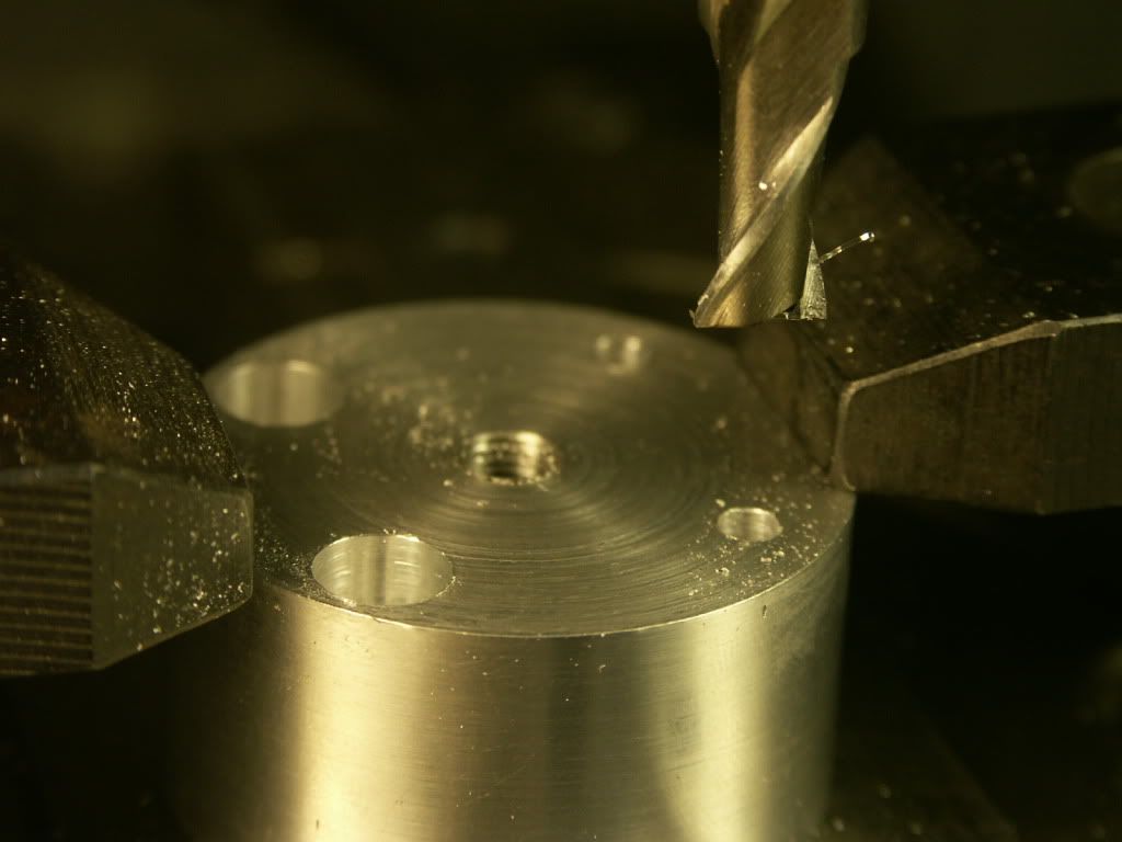
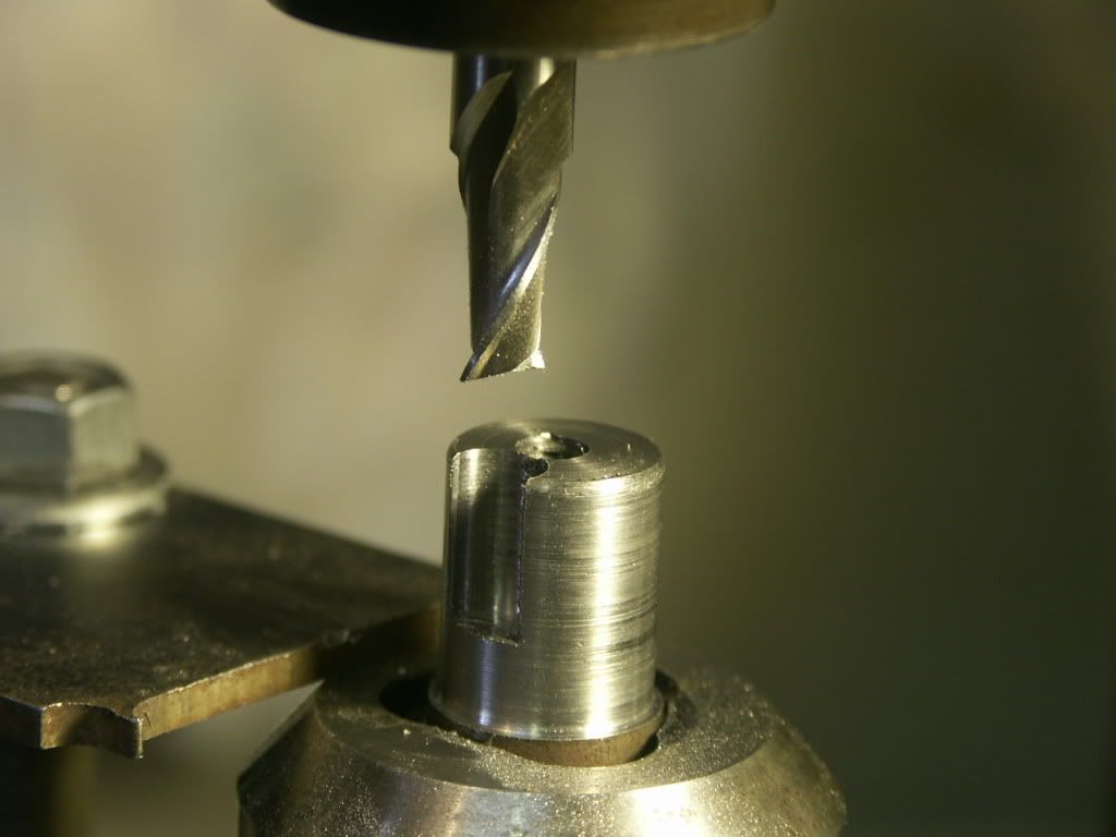
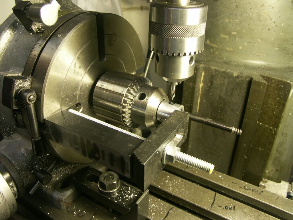
Plunge milling the cylinder bolt holes.
I've made two cast iron cylinders, per the original design. But, in an effort to save reduce weight, I started my own re-design using a cast iron bore with aluminum cooling fins.
Here I've successfully pressed the cast iron sleeves into the aluminum blanks, and then grooved the aluminum cooling fins. Next I made a jig to hold the cylinders in the milling machine to drill the intake, exhaust, and transfer ports, as shown here.

The next step was to mill clearance slots for the connecting rod.
Then back to the lathe to profile the cooling fins to complete the part.
Now I have 4 cylinders - two of solid cast iron and two of cast iron sleeves with aluminum cooling fins. The cast iron ones weigh about 3.8 oz, and the aluminum ones weigh 2.5 oz, so I think it was worth the effort.
The cylinder head is next. Unlike most miniature diesel engines, the contra-piston in this design is entirely in the head, and sealed by a Viton o-ring, which will become obvious later. There is also an o-ring between the cylinder and the cylinder head.
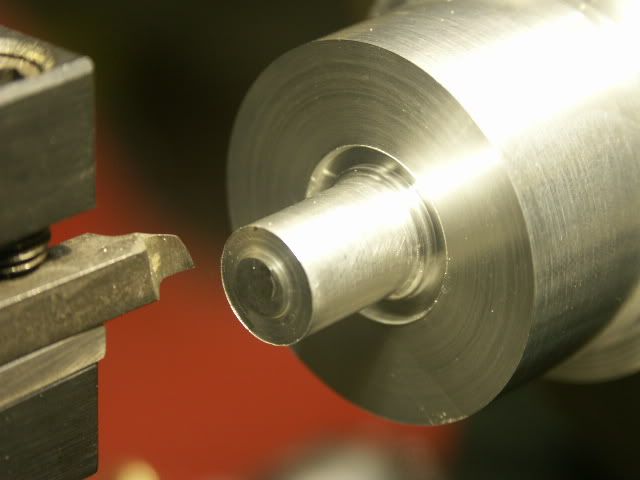
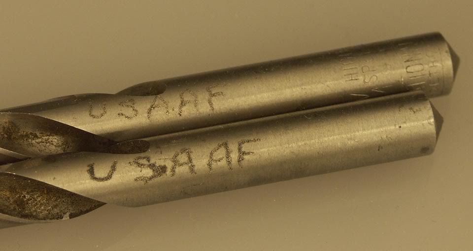
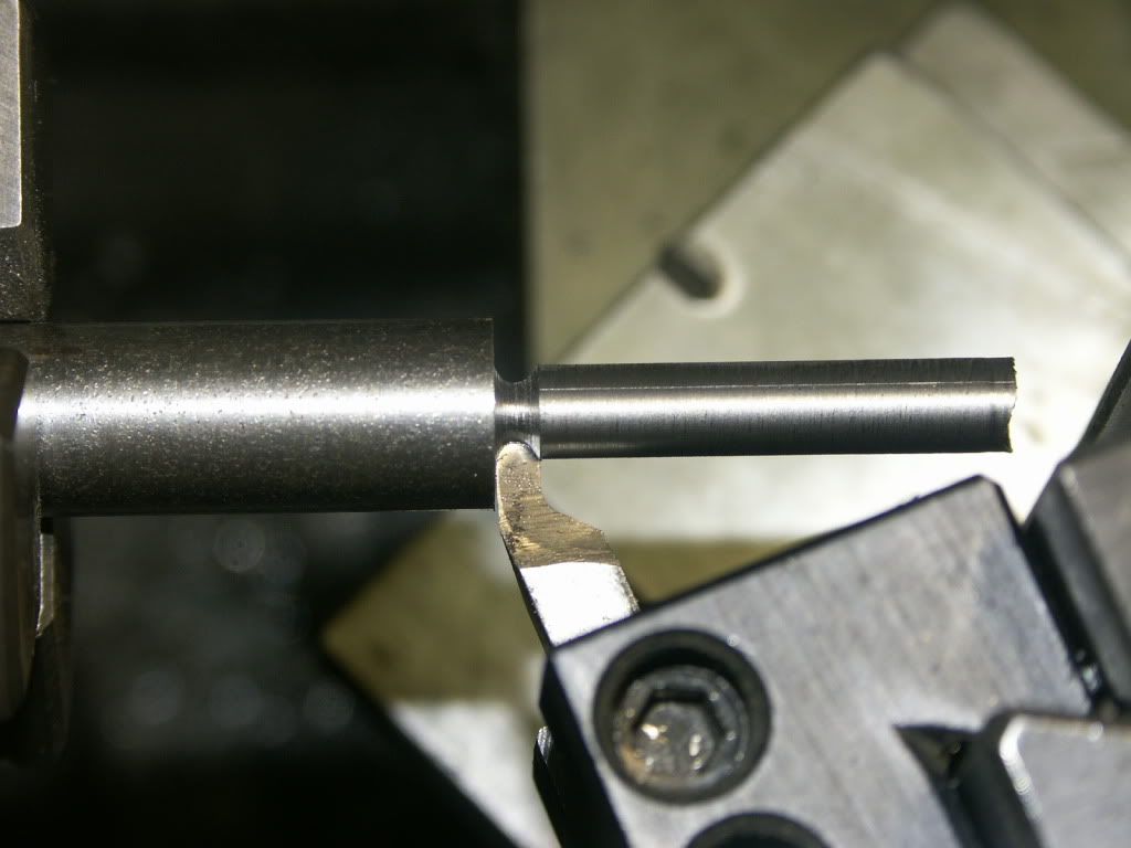
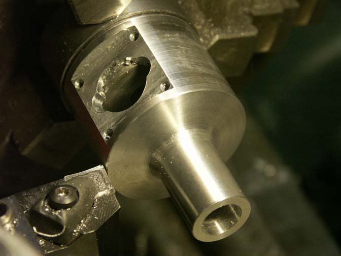
This photo shows the face-grooving operation for the o-ring gland between the cylinder and the cylinder head. The spigot in the center will eventually be shortened, but the stub of it will extend into the cylinder bore. The spigot presents an obstacle to the grooving tool, so in this case I had to mount the tool upside-down and reverse the lathe spindle. I usually use tungsten carbide tooling, but have to use high speed steel for special features like this. Fortunately for me, I have a couple hundred lathe bits that have been sharpened by my dad and my Uncle Frank, but primarily by my dad's father, who was a tool-room machinist. Inevitably I can find a tool bit that will work for special jobs like this, and I suspect that a lot of them date back to WWII. I haven't had to grind a new tool bit for the past 15 years, and have probably forgotten how. I just paw thru those bits, find the right shape, hone it a little, and go to work.
I had already begun making two cast iron cylinders before I made the one with aluminum fins, so although I'm making three engines, I am making 4 cylinders. When milling the connecting rod clearance slots in the first cast iron cylinder, I inadvertently cut slightly into the bypass port. If I'm thinking this thru correctly, it probably wouldn't hurt engine performance at that location. However, the cylinder wall thickness is plenty adequate, and since I happen to have a .532" reamer that was handed down thru the generations, I decided to ream the cylinder to that size. It fixed the problem and I decided to ream one of the aluminum cylinders, too. Reaming any larger would compromise the head gasket o-ring seal. That cylinder was originally 70 grams, and after reaming it weighed 64 grams, for a surprising 8.5% weight reduction . Hopefully, that will come with a little more power, too. Those two cylinders will now have a displacement of .22 cu. in. The original design is .20 cu. In.
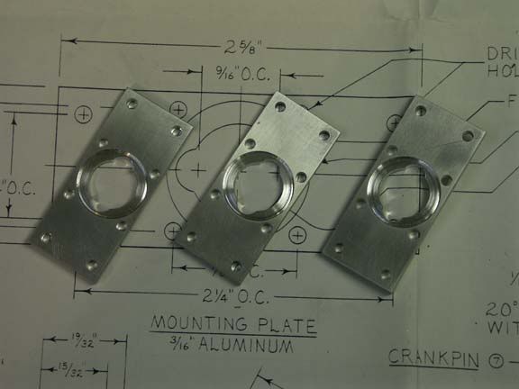
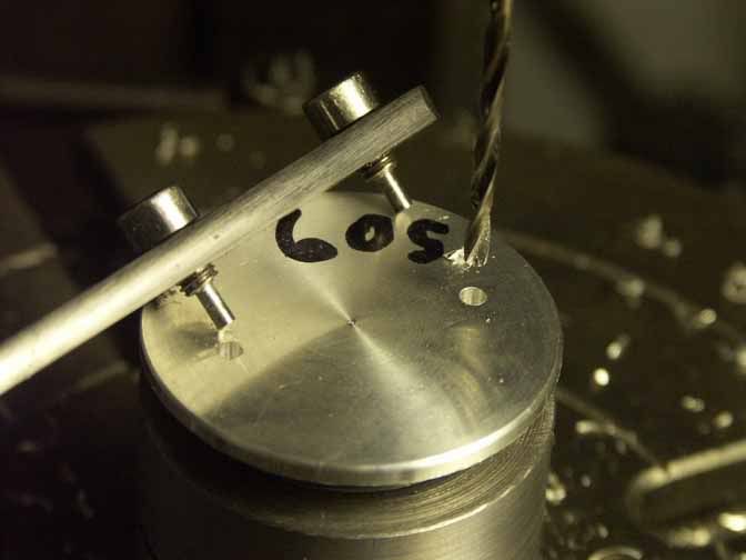
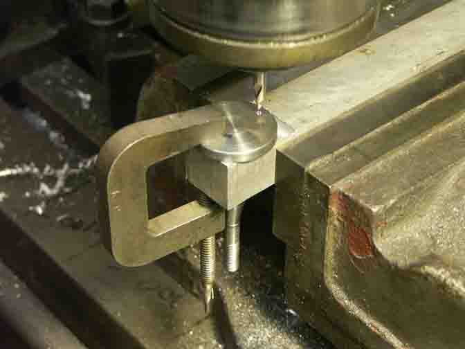
The next step was to mount the cylinder heads on the rotary table to drill and counterbore the bolt holes.
The cylinder head in the photo is the one for the .500" bore, so its spigot fit nicely into my existing rotary table center. The larger diameter of the .532" bores required a diversion to make the necessary bushing
The cylinder head will have a hemispherical profile. The building instructions give coordinates for roughing out this hemisphere. I don't have a radius turning attachment for my lathe, and this may be a good reason to make one. I have collected several magazine articles about how to make one, so I took a diversion here to decide whether I want to make one now.
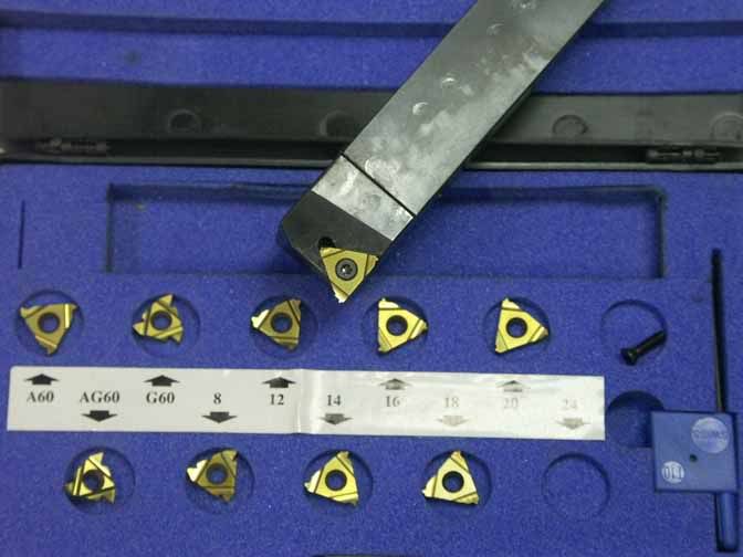
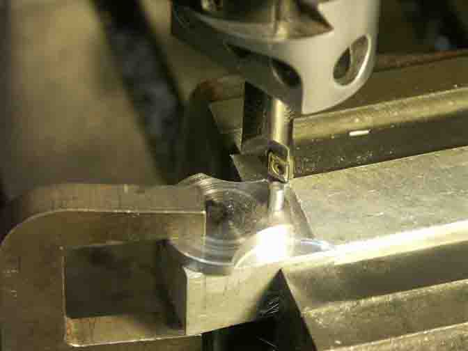
I've counted up 23 articles in my files about how to make radius turning attachments for lathes. But making most of those attachments would entail a project of comparable scale to making this engine. In the 28 years that I've had a lathe, this is the first occasion I've encountered where I need to cut a hemispherical shape, so I wasn't sure how much I would use such a dedicated tool in the future. Fortunately, one of my articles is one that I had photocopied about 30 years ago from "School Shop" magazine titled "Ball and Arc Turning Simplified". It describes how to generate a hemisphere just using the lathe compound tool rest swept by hand. Unfortunately, my lathe's compound doesn't retract from its pivot point as much as the one in the article, so I had to figure out another way to hold my cutting tools. Here's my solution to the problem.
Since I had suitable indexable tool holders with 1" and 3/4" shanks, I just needed to fashion a clamp to hold the toolholders so the inserts were at the centerline of the compound and shimmed up to the lathe centerline. It took a lot more time to figure out WHAT to do than to actually do it. The downside to this approach is that I am limited to a diameter of 2 1/4" because larger diameters will hit the compound. And with the cutting tool retracted from the headstock this way, I couldn't use my regular chuck - the carriage hit its stop and the tool wouldn't reach the left end of the part. Since the stub end of this part had already been made, I was hampered but found that if I used my drill chuck with a precarious grip on the part it would just barely work. And it exceeded my expectations!
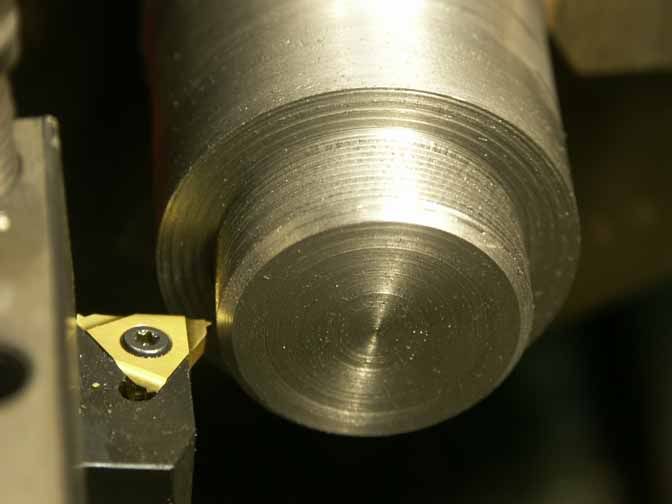
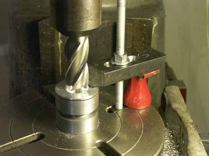
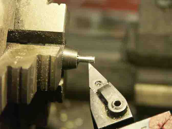
Just for giggles, I tried both a full radius insert and a 35 degree diamond, both shown here.
They both worked well. The full radius insert had an easier time in the interrupted cuts but had minor chatter. The 35 degree diamond didn't chatter but took more pounding in the interrupted cuts. Just as a text book might tell you! Since the parts weren't gripped well in the chuck and the drill chuck isn't made for side loads and was held only with the friction of the Morse taper, I kept my depths of cut at .008" or below, but it didn't take long before all three parts were done. Next time, if I make the stub long enough to use the regular chuck, I could get just a little more aggressive, but it would still be hanging out several inches from the chuck.
The original plans for this engine don't call for cutting cooling fins on the cylinder head. However, since the grooving tool that I had made worked pretty well and I saw that by doing so I could see weight savings without losing strength, I went ahead and grooved the cylinder heads. And since the rotary table was still set up, I increased the counterbores around the bolt holes to 3/8". It is a tough call to know when to call it "good" and to "leave good enough alone". There is always the potential for me to make a ham-fisted move and scrap all the work I have invested into a part so far. I've reached the point of diminishing returns, so I'm calling this part "good".
Before this grooving, the cylinder heads weighed 1.8 oz. Afterwards, they weighed 1.4 oz. The stub that fits into the cylinder will be shortened to adjust the piston clearance at final assembly, so I estimate that the final part will weigh about 1.2 oz. Grooving the fins had an additional bonus of providing a better gripping surface than the hemisphere for re-chucking to trim that stub.
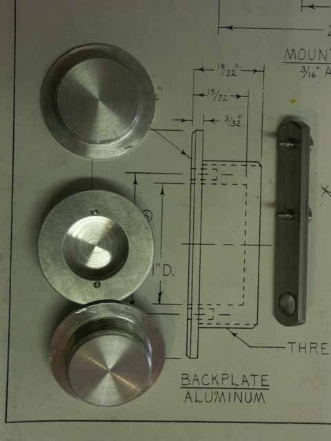
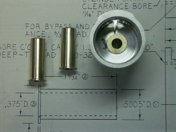
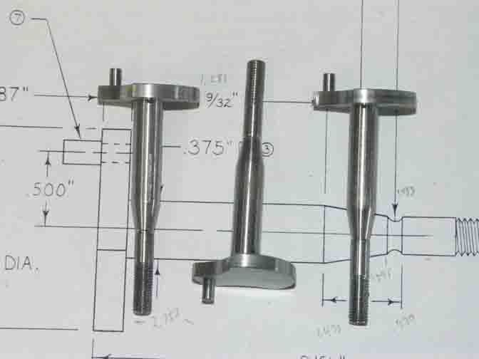
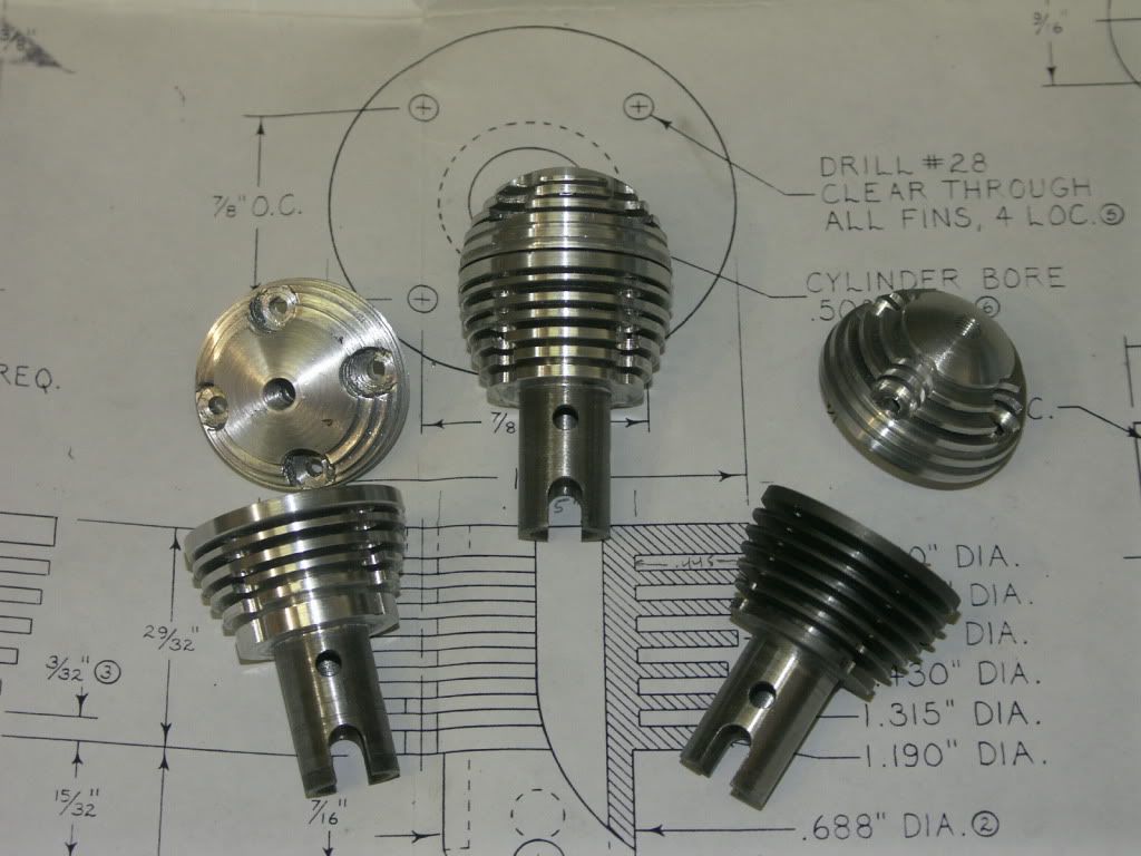
Here are the cylinder assemblies to date.
I'm at the stage with machining skills that I wouldn't consider building an IC engine without step-by-step directions, but I'm starting to make more parts the way I want to make them rather than follow the instructions. So it is with the "cylinder jacket" - an aluminum sleeve into which screw the intake and exhaust ports radially, and into which the bypass/transfer port is cut axially. Effectively, one feature had to be cut in each of the three axes - x, y, and z. The written instructions suggest using an alignment gage along with a dial indicator to dial in each operation, which I would have done if I was only making one of these parts, but it sounds rather tedious when cutting three features into 4 parts. Being lazy, I conceived a way which minimized the use of the dial indicator and allowed quick repetition of each operation.
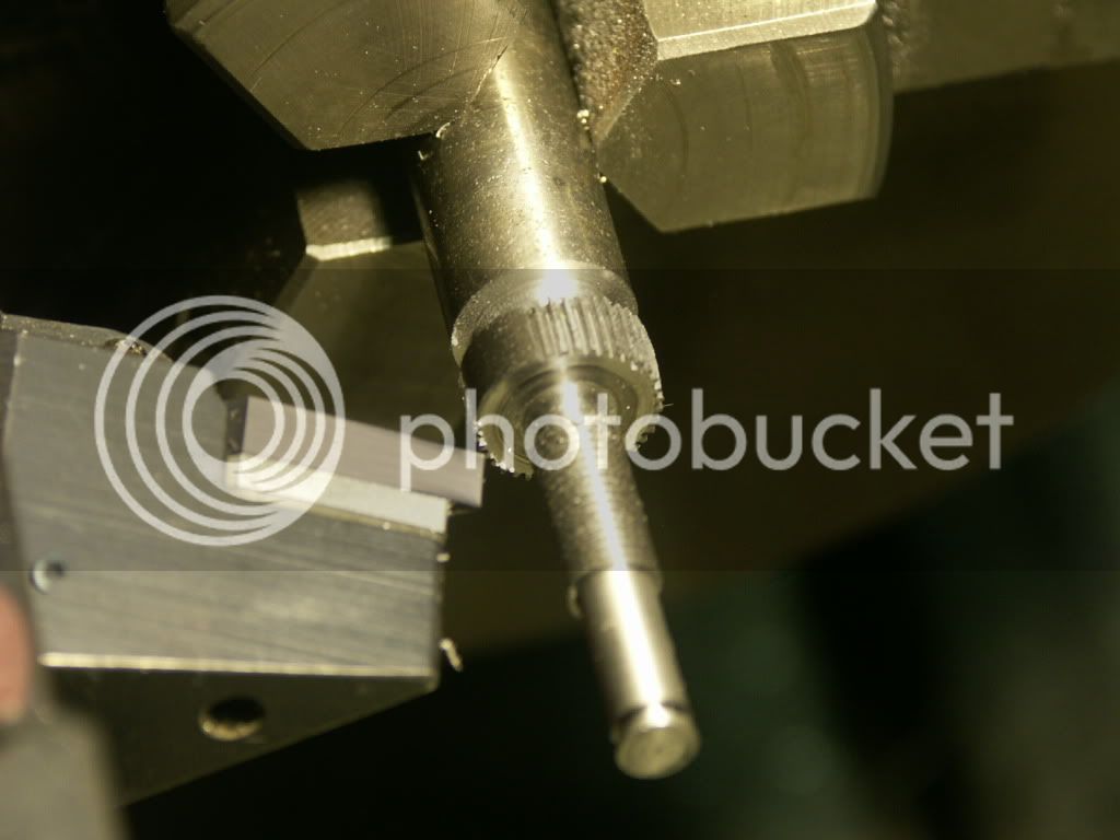
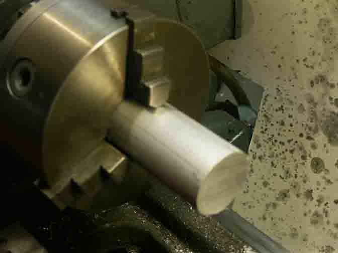
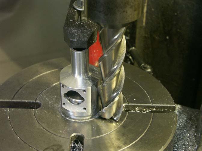
First, I turned the four cylinder jacket blanks - simple aluminum cylinders with a bore to match the cast iron cylinders. Then I made a mandrel that was a tight fit in the bores, and mounted the mandrel vertically on the rotary table, show here.
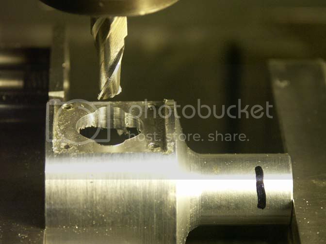
The bypass port calls for a vertical plunge mill operation that only partly engages the jacket ID, so I set up the spindle to the proper location and then , first, plunged the 5/16" end mill into the mandrel to provide the necessary clearance. Next, one at a time I slipped the four cylinder jackets onto the mandrel and plunge milled again.
This not only cut the necessary bypass port, but provided a way to quickly align the cylinder jackets for their subsequent drilling operations. Next, the rotary table was positioned so it held the parts horizontally, and dialed-in square to the table movements.
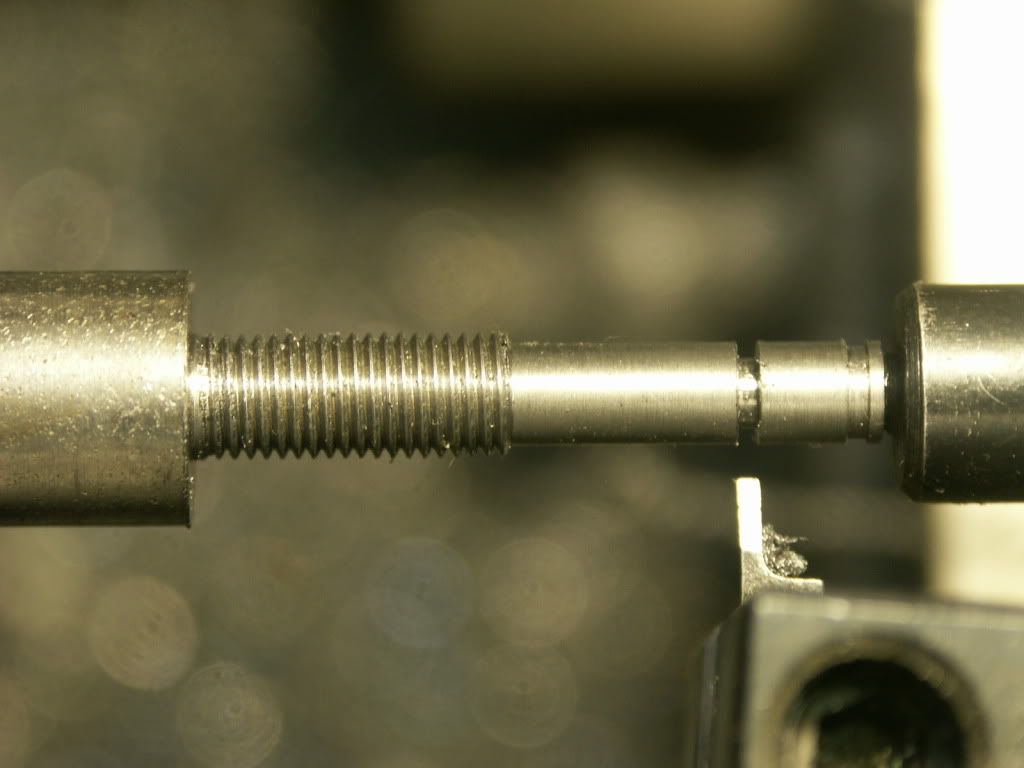
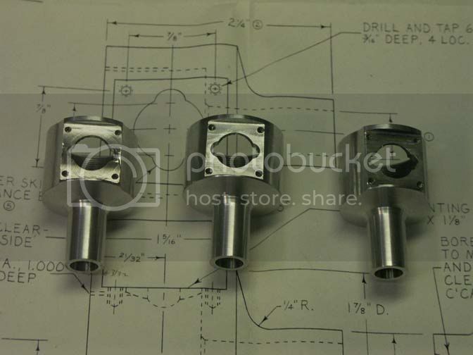
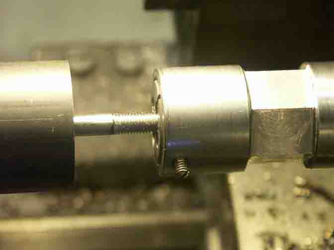
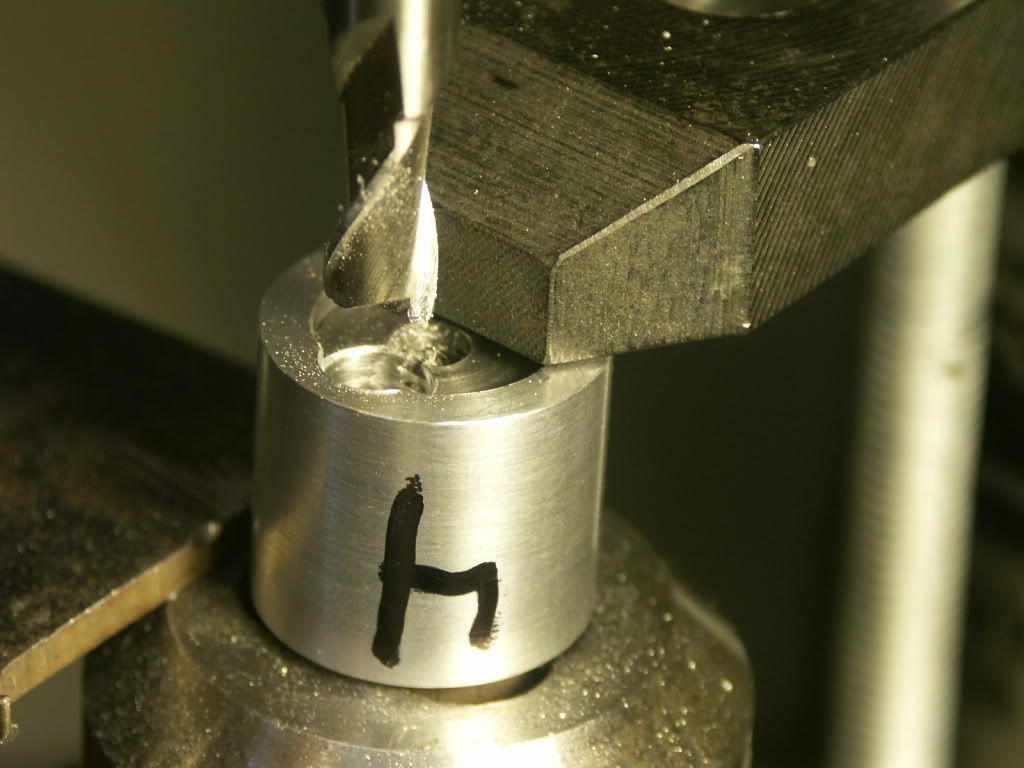
In this way, one of the ports was center drilled, counterbored, drilled and tapped on each of the four parts, the rotary table was indexed 90 degrees, and the second set of ports was completed. The black rod with a short thread is the 5/16" pin I used for aligning each part.
Bob
I plan to make three of the diesels. One to fasten to my workbench. The second to give to my brother-in-law. He lives in southern California, and is big into model airplanes - primarily R/C sailplanes and Old-Timer style free flight. It would be cool to see one of my engines take to the air - and he's the man who can make it happen. Perhaps the third one will take to the air here in Salt Lake City.
In this photo, I've just finished turning and grooving the first engine cylinder for the "MLA Diesel".
The cylinder is cast iron, and rather heavy. It alone weighs 4.6 oz. (130 gm). About 10% of the material will be removed in subsequent machining, but it will still be about 4 oz. when completed. I haven't weighed the "Mate" diesel I just recently completed, but the drawings say it weighs 150 gm - in total. I'm guessing now that this engine will weigh about 12 oz - without a propeller. I am starting to make efforts to reduce the weight as much as practical.
The grooves are .063" wide and .445" deep. Since I have a tool block holding 1.25" indexable partoff blades on the back side of the cross-slide, I made a groover by machining a broken Iscar blade. They are made from something like 4140, but it worked great for the aluminum and cast iron fins.
Plunge milling the cylinder bolt holes.
I've made two cast iron cylinders, per the original design. But, in an effort to save reduce weight, I started my own re-design using a cast iron bore with aluminum cooling fins.
Here I've successfully pressed the cast iron sleeves into the aluminum blanks, and then grooved the aluminum cooling fins. Next I made a jig to hold the cylinders in the milling machine to drill the intake, exhaust, and transfer ports, as shown here.
The next step was to mill clearance slots for the connecting rod.
Then back to the lathe to profile the cooling fins to complete the part.
Now I have 4 cylinders - two of solid cast iron and two of cast iron sleeves with aluminum cooling fins. The cast iron ones weigh about 3.8 oz, and the aluminum ones weigh 2.5 oz, so I think it was worth the effort.
The cylinder head is next. Unlike most miniature diesel engines, the contra-piston in this design is entirely in the head, and sealed by a Viton o-ring, which will become obvious later. There is also an o-ring between the cylinder and the cylinder head.
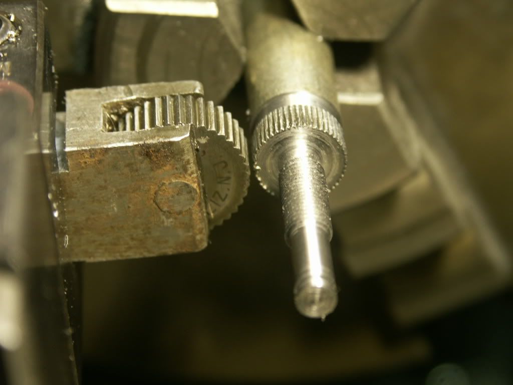
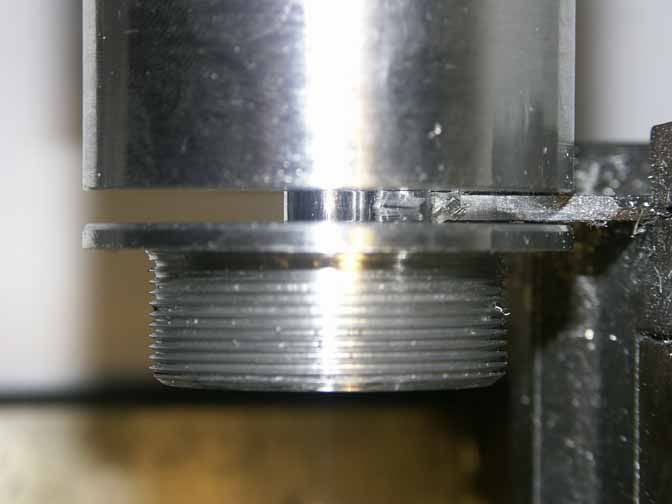
This photo shows the face-grooving operation for the o-ring gland between the cylinder and the cylinder head. The spigot in the center will eventually be shortened, but the stub of it will extend into the cylinder bore. The spigot presents an obstacle to the grooving tool, so in this case I had to mount the tool upside-down and reverse the lathe spindle. I usually use tungsten carbide tooling, but have to use high speed steel for special features like this. Fortunately for me, I have a couple hundred lathe bits that have been sharpened by my dad and my Uncle Frank, but primarily by my dad's father, who was a tool-room machinist. Inevitably I can find a tool bit that will work for special jobs like this, and I suspect that a lot of them date back to WWII. I haven't had to grind a new tool bit for the past 15 years, and have probably forgotten how. I just paw thru those bits, find the right shape, hone it a little, and go to work.
I had already begun making two cast iron cylinders before I made the one with aluminum fins, so although I'm making three engines, I am making 4 cylinders. When milling the connecting rod clearance slots in the first cast iron cylinder, I inadvertently cut slightly into the bypass port. If I'm thinking this thru correctly, it probably wouldn't hurt engine performance at that location. However, the cylinder wall thickness is plenty adequate, and since I happen to have a .532" reamer that was handed down thru the generations, I decided to ream the cylinder to that size. It fixed the problem and I decided to ream one of the aluminum cylinders, too. Reaming any larger would compromise the head gasket o-ring seal. That cylinder was originally 70 grams, and after reaming it weighed 64 grams, for a surprising 8.5% weight reduction . Hopefully, that will come with a little more power, too. Those two cylinders will now have a displacement of .22 cu. in. The original design is .20 cu. In.
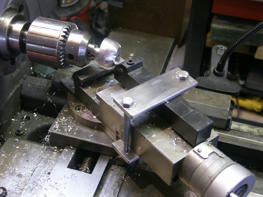
The next step was to mount the cylinder heads on the rotary table to drill and counterbore the bolt holes.
The cylinder head in the photo is the one for the .500" bore, so its spigot fit nicely into my existing rotary table center. The larger diameter of the .532" bores required a diversion to make the necessary bushing
The cylinder head will have a hemispherical profile. The building instructions give coordinates for roughing out this hemisphere. I don't have a radius turning attachment for my lathe, and this may be a good reason to make one. I have collected several magazine articles about how to make one, so I took a diversion here to decide whether I want to make one now.
I've counted up 23 articles in my files about how to make radius turning attachments for lathes. But making most of those attachments would entail a project of comparable scale to making this engine. In the 28 years that I've had a lathe, this is the first occasion I've encountered where I need to cut a hemispherical shape, so I wasn't sure how much I would use such a dedicated tool in the future. Fortunately, one of my articles is one that I had photocopied about 30 years ago from "School Shop" magazine titled "Ball and Arc Turning Simplified". It describes how to generate a hemisphere just using the lathe compound tool rest swept by hand. Unfortunately, my lathe's compound doesn't retract from its pivot point as much as the one in the article, so I had to figure out another way to hold my cutting tools. Here's my solution to the problem.
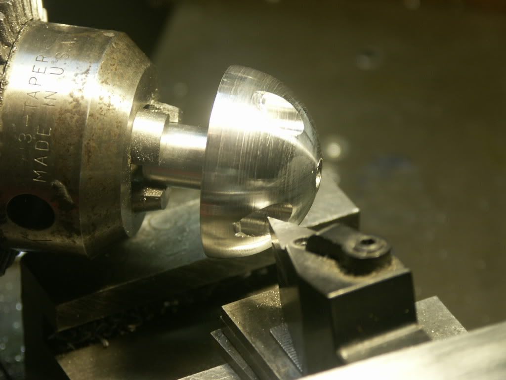
Since I had suitable indexable tool holders with 1" and 3/4" shanks, I just needed to fashion a clamp to hold the toolholders so the inserts were at the centerline of the compound and shimmed up to the lathe centerline. It took a lot more time to figure out WHAT to do than to actually do it. The downside to this approach is that I am limited to a diameter of 2 1/4" because larger diameters will hit the compound. And with the cutting tool retracted from the headstock this way, I couldn't use my regular chuck - the carriage hit its stop and the tool wouldn't reach the left end of the part. Since the stub end of this part had already been made, I was hampered but found that if I used my drill chuck with a precarious grip on the part it would just barely work. And it exceeded my expectations!
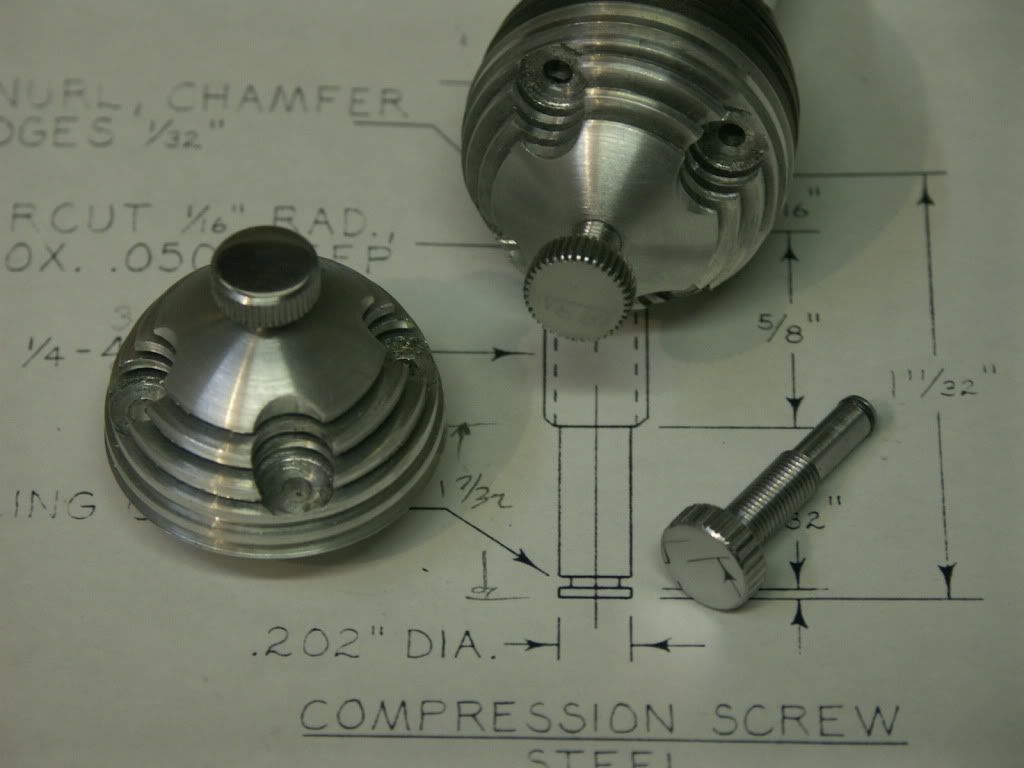
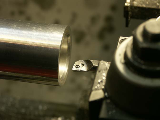
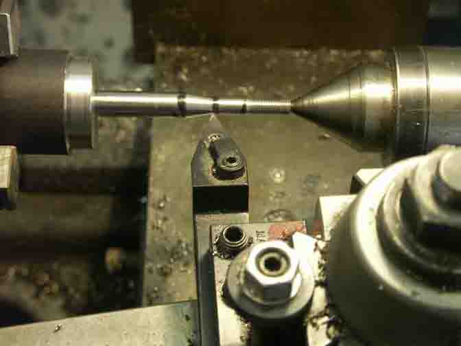
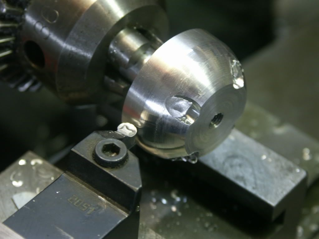
Just for giggles, I tried both a full radius insert and a 35 degree diamond, both shown here.
They both worked well. The full radius insert had an easier time in the interrupted cuts but had minor chatter. The 35 degree diamond didn't chatter but took more pounding in the interrupted cuts. Just as a text book might tell you! Since the parts weren't gripped well in the chuck and the drill chuck isn't made for side loads and was held only with the friction of the Morse taper, I kept my depths of cut at .008" or below, but it didn't take long before all three parts were done. Next time, if I make the stub long enough to use the regular chuck, I could get just a little more aggressive, but it would still be hanging out several inches from the chuck.
The original plans for this engine don't call for cutting cooling fins on the cylinder head. However, since the grooving tool that I had made worked pretty well and I saw that by doing so I could see weight savings without losing strength, I went ahead and grooved the cylinder heads. And since the rotary table was still set up, I increased the counterbores around the bolt holes to 3/8". It is a tough call to know when to call it "good" and to "leave good enough alone". There is always the potential for me to make a ham-fisted move and scrap all the work I have invested into a part so far. I've reached the point of diminishing returns, so I'm calling this part "good".
Before this grooving, the cylinder heads weighed 1.8 oz. Afterwards, they weighed 1.4 oz. The stub that fits into the cylinder will be shortened to adjust the piston clearance at final assembly, so I estimate that the final part will weigh about 1.2 oz. Grooving the fins had an additional bonus of providing a better gripping surface than the hemisphere for re-chucking to trim that stub.
Here are the cylinder assemblies to date.
I'm at the stage with machining skills that I wouldn't consider building an IC engine without step-by-step directions, but I'm starting to make more parts the way I want to make them rather than follow the instructions. So it is with the "cylinder jacket" - an aluminum sleeve into which screw the intake and exhaust ports radially, and into which the bypass/transfer port is cut axially. Effectively, one feature had to be cut in each of the three axes - x, y, and z. The written instructions suggest using an alignment gage along with a dial indicator to dial in each operation, which I would have done if I was only making one of these parts, but it sounds rather tedious when cutting three features into 4 parts. Being lazy, I conceived a way which minimized the use of the dial indicator and allowed quick repetition of each operation.
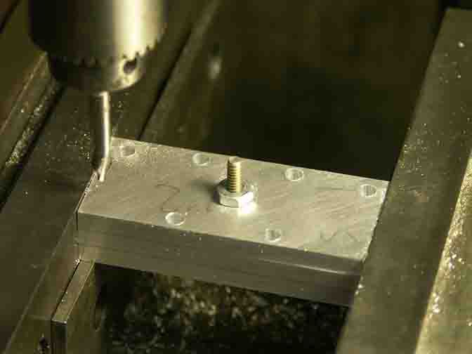
First, I turned the four cylinder jacket blanks - simple aluminum cylinders with a bore to match the cast iron cylinders. Then I made a mandrel that was a tight fit in the bores, and mounted the mandrel vertically on the rotary table, show here.
The bypass port calls for a vertical plunge mill operation that only partly engages the jacket ID, so I set up the spindle to the proper location and then , first, plunged the 5/16" end mill into the mandrel to provide the necessary clearance. Next, one at a time I slipped the four cylinder jackets onto the mandrel and plunge milled again.
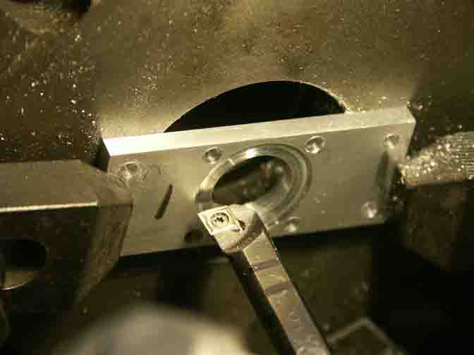
This not only cut the necessary bypass port, but provided a way to quickly align the cylinder jackets for their subsequent drilling operations. Next, the rotary table was positioned so it held the parts horizontally, and dialed-in square to the table movements.
In this way, one of the ports was center drilled, counterbored, drilled and tapped on each of the four parts, the rotary table was indexed 90 degrees, and the second set of ports was completed. The black rod with a short thread is the 5/16" pin I used for aligning each part.
Bob