MLA Diesel - Work in Progress

Home Model Engine Machinist Forum

Help Support Home Model Engine Machinist Forum:

This site may earn a commission from merchant affiliate links, including eBay, Amazon, and others.
Mike N -

This has been a fun engine to build. The enjoyment has been enhanced because I have been in email communication with Andy, and he has been answering my questions and reading my posts. His instructions are well written for a beginner to follow, but the design allows room for someone to personalize the final product, if desired. I have not yet made the fuel tank. It utilizes a clear (or at least translucent) plastic 35mm film canister. I'm sure a substitute can be found, but if you plan to build this engine, it may we wise to go now to your local film processor to get a few discarded canisters - before film becomes obsolete. ;)

Bob G
 
Drive Washer and Front Washer

The front washer was a straight forward turning operation, but the Drive Washer took a little more thought and adjustment. The crankshaft and drive washer had matching tapers of 10 degrees per side, and this had to be a pretty accurate fit. When I turned the crankshaft, I pivoted the lathe compound to the left so it would allow me to use the tailstock center. To bore the washer, I had to pivot the compound to the right. This meant that two different scribe lines were used to read the set-over angle, causing a possible error between the two. By making repeated cuts with slight angle adjustments and inking with a marking pen, I found the point where I had good contact on the taper surface.

BoringDriveWasheremail.jpg

To bore this taper in a ¼” hole, I looked through my Grandpa’s boring bars, and found at least 5 miniature boring bars that would do the job. All of these had been hand made from HSS blanks or re-purposed tools. The shank of the one I used says “Bay State ¼-20 NC”, so this had obviously been a tap. Even after modification into a boring bar, this tool is STILL 4.5” long, so this must have been a very long reach tap. (History Lesson) - Bay State Tap and Die Company was also located in Mansfield, Massachusetts, like the S .W. Card Manufacturing Company that I mentioned in a previous post. Bay State was bought out by Cleveland Twist Drill about 50 years ago, whereas S. W. Card became a division of Union Twist Drill.

The plans for this engine don’t call for knurling the drive washer, and when I inquired to Andy Lofquist about this, he replied that slippage has never been a problem. Since I (very poorly) knurled the drive washer of the “Mate” diesel, I decided to knurl these, too, and use them as an exercise on how to do it better. Andy joked that the knurling operation would feed my fetish for weight reduction! The problem with knurling a flat face is that the inner and outer diameters move different distances per revolution, but the knurl can only go at one speed. This page at ModelEngineNews.org gave me suggestions on how to accomplish it.

http://modelenginenews.org/techniques/prop_drivers.html

FaceGroovingDriveWasheremail.jpg

To begin, I face-grooved the drive washer to allow two .100” wide rings of material to project .015”. These dimensions were arbitrarily chosen, but I didn’t want the knurls to be so deep that they might cause the propeller to run out of true, and the rings needed enough distance between them to allow the knurling tool to engage only one ring at a time. No, that isn’t a face-grooving tool that I’m using here. It is a VNGP OD turning insert. If I was going more than .015” deep, there would be a serious rubbing problem, but it handled this shallow cut just fine.

KnurlingDriveWasheremail.jpg

The knurling tool was fed into each ring separately, and the carriage stop limited the depth of cut to .015”. The knurls are not as deep as the example on the web page above, but should give a good grip to the propeller.

TrimmingCrankcasetoLengthemail.jpg

Once the washers were done, the crankcase could be to trimmed to a length that permitted a .005-.010” end clearance for the crankshaft. Measuring this clearance required removing the crankcase from the lathe and inserting the crankshaft – multiple times. Once again, I was glad I had made a thread gage which doubled as a mounting fixture, and made this operation much faster and more precise.

FinishedWashersemail.jpg

The finished washers.

Bob G

 
Connecting Rods

I decided to deviate slightly from the order of steps in the written description for making the connecting rods.

ReamingConrodHolesemail.jpg

The spacing, diameter, and alignment of the two holes are the most critical features of this part, and I figured that I had the best control over these if I drilled and reamed these holes in the first operation. I first milled a flat to help insure that the holes didn’t wander.

TurningConrodemail.jpg

The workpiece was then chucked in the lathe and steadied by the tailstock. The “big end” and “little end” diameters were turned, and then the shank. I like turning “Stessproof” steel, particularly when parting off – the chips don’t bind in the groove.

Millingconrodendsemail.jpg

I rigged up a simple clamping fixture to hold the connecting rod, with a vee groove to orient the shank, so I could mill the ends flat. Since the ends were unsupported, I limited my depths-of-cut to .005”. The holes having already been drilled, I aligned the workpiece with an 1/8” rod held in the milling collet.


Radiusconrodendemail.jpg

In the past, I’ve radiused connecting rod ends with the side of an end mill, either using a rotary table or sweeping by hand. The procedure has never been very satisfactory. Using the rotary table, it is hard to see how far to rotate. Sweeping by hand was faster, but having my fingers so close to a grabbing cutter just felt WRONG, and not very safe. After reading on this website (http://modelenginenews.org/restored/conrods.html) about sweeping by hand while using the end of an end mill, I decided to give it a try. It worked pretty well, but still makes me nervous. I felt like a teacher should have been tapping me on the shoulder, saying “Don’t do that!” There is still a tendency for the cutter to grab the workpiece, so I once again limited my depths-of-cut to .005”. My 3 or 4 flute cutters had less of a tendency to grab than the 2 flute cutter. Try at your own risk!

Finishedconrodsemail.jpg

After a little de-burring, all the connecting rods were done, and I still have all my fingers.

Bob G
 
Nice work Bob!
I've kinda wondered about that method for rod ends, I think I'll stick to filing buttons. Thanks for the write-up.

Cheers

Jeff
 
Piston

BoringPistonIDemail.jpg

The piston was begun by drilling and boring the ID in Stressproof.

DrillingWristPinHoleemail.jpg

Then it was moved to the mill to drill and ream the blind hole for the wrist pin.

MillingConrodClearanceemail.jpg

Using the wrist pin hole for alignment, I clamped the piston vertically in the vise to plunge mill the slot for the connecting rod end. This was a poor setup for clamping a round part, so I limited the step-over to .025” per plunge. The resulting scallops were removed by full-depth slot milling.

PlungemillingBaffleemail.jpg

Then the baffle on the top of the piston was formed by a simple plunge. The top of the piston will be at the center of the resulting groove, but the excess material will be left on for now, providing a stub to hold the piston for lapping.

FinishedPistonsemail.jpg

The pistons after preliminary machining, but before lapping. I’m building 3 complete engines, plus one extra piston and cylinder assembly. The chucking stubs have different lengths on each piston because these parts were made from my last 4 scrap pieces of Stressproof, and the shortest ones were just barely long enough.

Wrist Pin

WristPinemail.jpg

The wrist pins were turned from 1/8” drill rod, and then hardened and tempered. Despite the fact that the wrist pins were among the smaller parts I’ve ever made, they required a hole in one end to accept a press-fit aluminum pad that prevents the wrist pin from scoring the cylinder wall. You may be able to see the joint on the left end of the part. I only photographed one of the four wrist pins here because they were each custom fit for a smooth slip fit to their piston, and I didn’t want to risk mixing them up while they posed for the camera.

Cylinder Studs

CylinderStudsemail.jpg

Cutting the 24 threaded ends of the studs was the only operation so far that became tedious.

Bob G
 
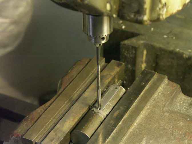
Exhaust Stack and Nut

KnurlingExhaustNutemail.jpg

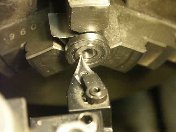
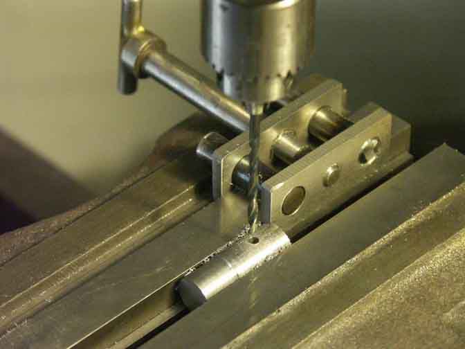
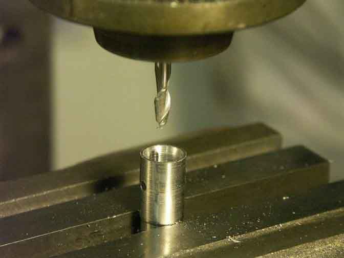
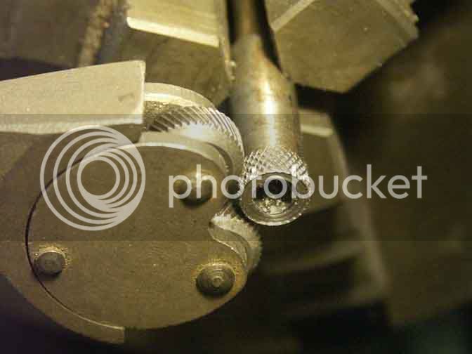
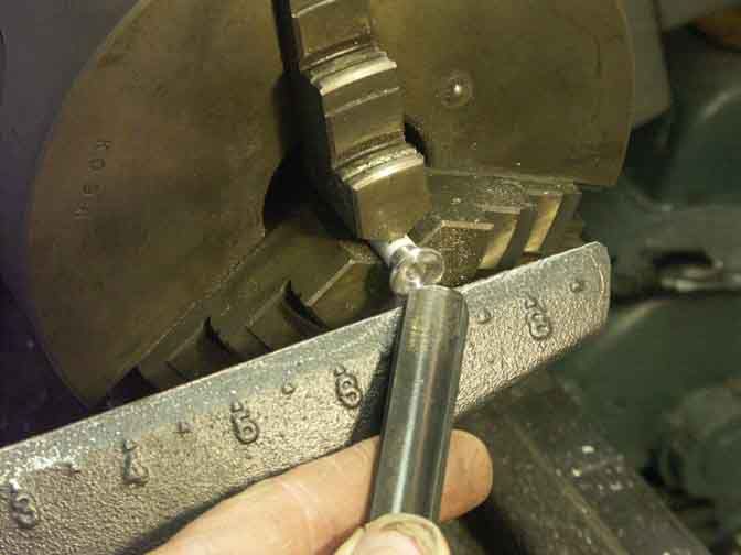
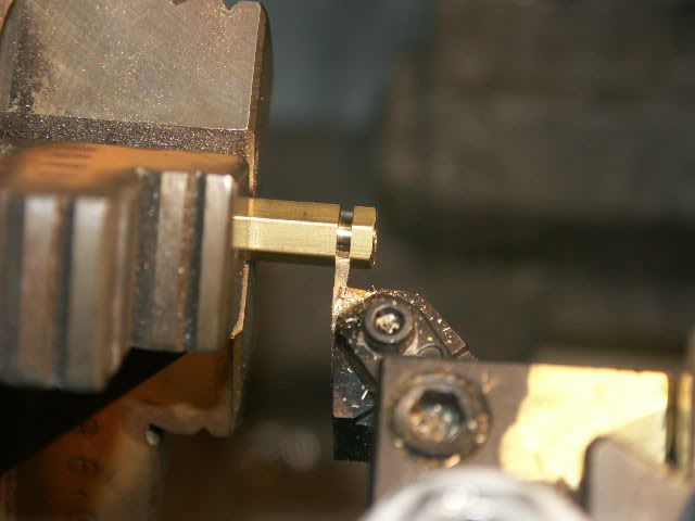
The exhaust nut was knurled, drilled, and tapped for a 5/16-24 thread. Since my previous straight pattern knurls had worked well, I decided to take the time to adapt my two Armstrong diamond pattern knurlers to fit my lathe. I used the one with the finer pitch. The puzzle to me was that the two wheels on this tool were of slightly different diameters (.622” and .613”), so it didn’t make sense to run thru the calculations to determine the proper part OD before knurling, but they seemed to track okay. The wheel diameters of the coarse pitch tool match much better, so perhaps one of these wheels wore faster than the other.

TurningODofExhaustNutemail.jpg

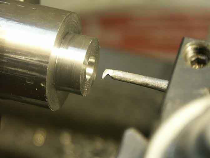
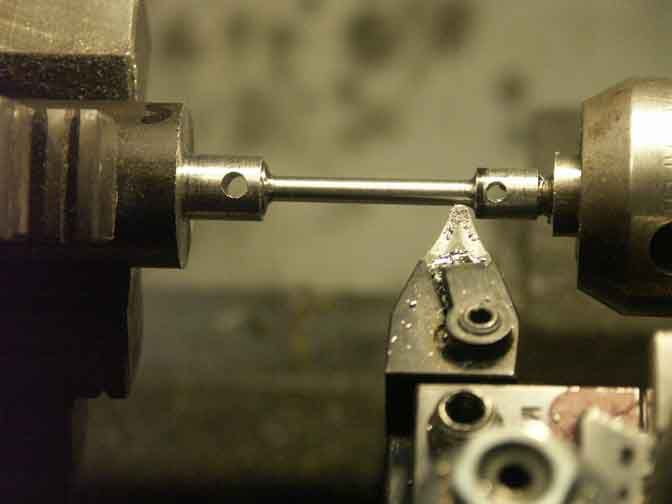
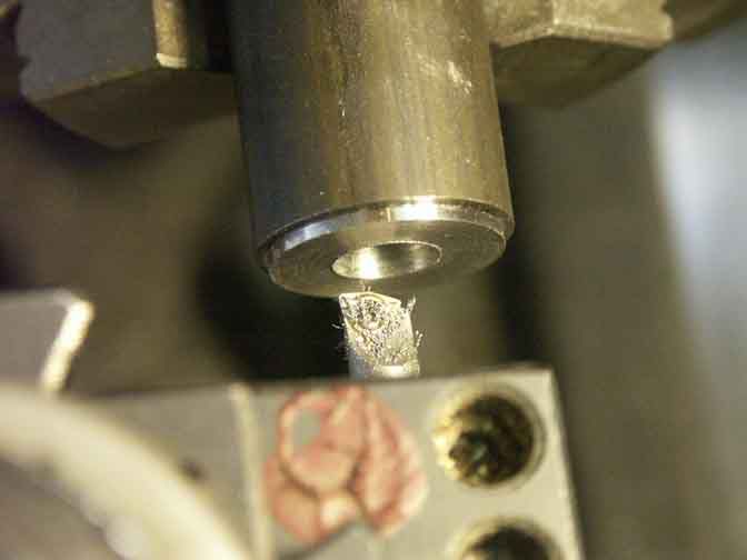
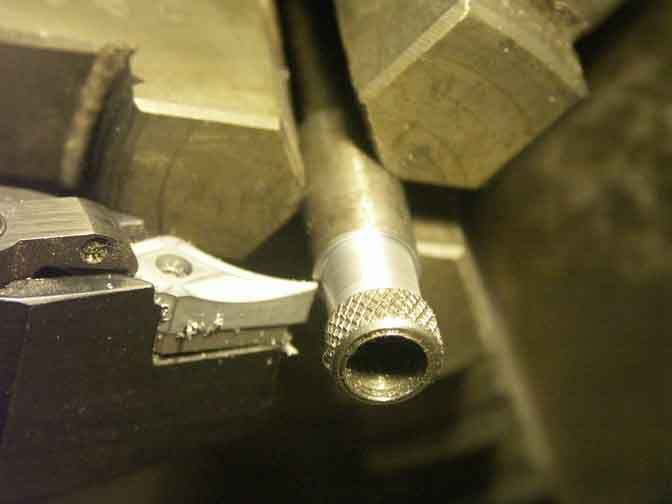
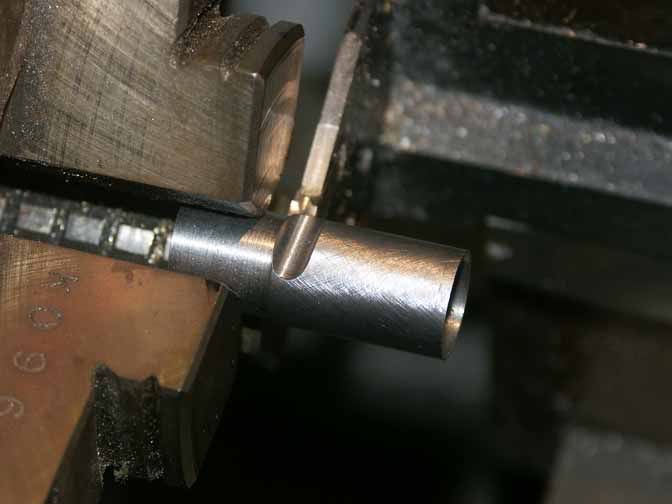
Then the straight section of the nut was turned, and the nut was parted off.

TurningODofExhaustStackemail.jpg

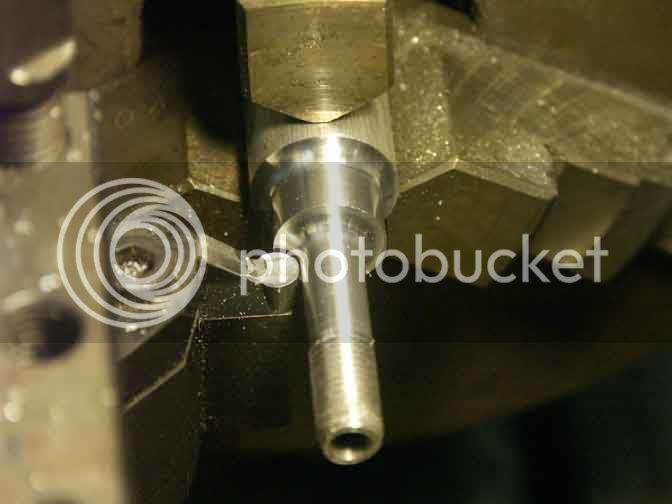
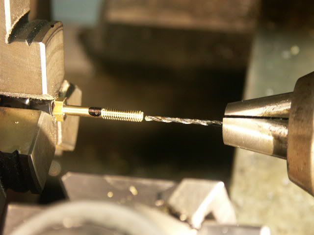
The exhaust stack was turned from solid aluminum, the 5/16”-24 thread was cut with a die, it was drilled thru, and then parted off. My full radius turning insert was perfect for the outside contour of the trumpet shape.

My threading die had been misplaced into the tool box in which I keep my historic tools – things that are either fragile, near 100 years old, or taps and dies with obsolete thread sizes and pitches. Opening that box presented me with another History Lesson.

PWthreadgageemail.jpg

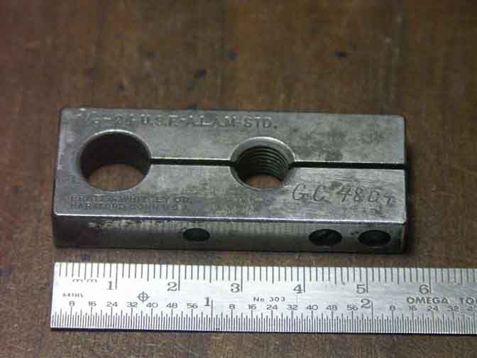
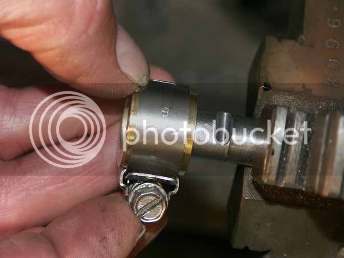
It is my guess that this is an adjustable thread gage. It is marked “3/8-24 U.S.F – A.L.A.M. STD.” “Pratt & Whitney Co., Hartford, Conn.U.S.A.”, and what looks like a hand-inscribed “GC4804”. In itself, the gage is not too notable, but I had never heard of the A.L.A.M. Standard before – so I looked it up.

The ALAM was the Association of Licensed Automobile Manufacturers, the group that was originally formed to challenge the Selden Patent claim to cover all automobiles, but then became the enforcer of the royalty payments from American automobile manufacturers. When Ford Motor Company was denied entry into the ALAM, Henry Ford brought a lawsuit that ultimately led to the invalidation of the Selden patent in 1911.

Wikipedia has more info on that. http://en.wikipedia.org/wiki/Association_of_Licensed_Automobile_Manufacturers

So why does my Pratt & Whitney gage say “A.L.A.M. STD”? My “American Machinists’ Handbook” by Colvin and Stanley (1914) gives a clue. On the page defining fine pitch threads, it says, “This was originally known as the A.L.A.M. Standard, but is now the S.A.E. (Society of Automobile Engineers).” Further on, under the heading “Gas Engine Horse-Power”, it says, “The A.L.A.M. rating for gasoline engines, which means the standard adopted by the American Licensed Automobile Manufacturers, is based on the assumption that the piston speed is 1000 feet per minute in all cases. This gives 1500 revolutions per minute for a 4-inch stroke motor, which is about average practice. Since the defeat of the Selden patent the A.L.A.M. has ceased to exist and this is now known as the S.A.E.standard.”

So it sounds like the defenders of the Selden patent did more than just defend the patent. They apparently set some early standards for the American auto industry, and set some things in motion that are still being used in America today.

TurningTrumpetemail.jpg

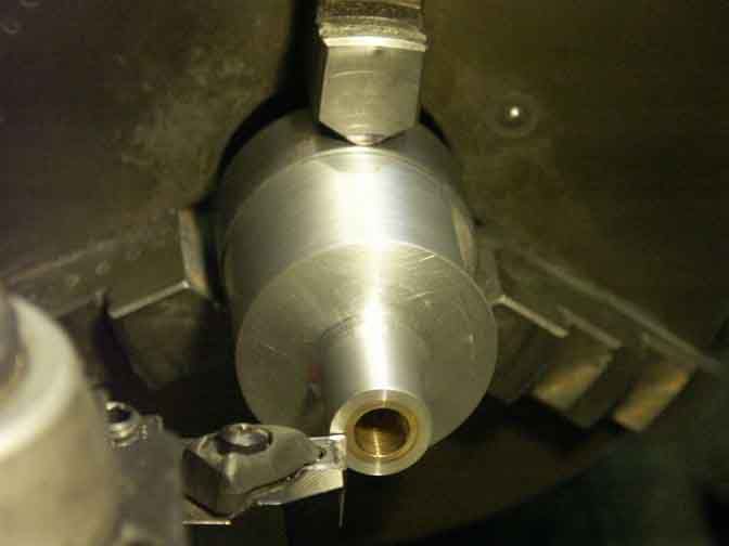
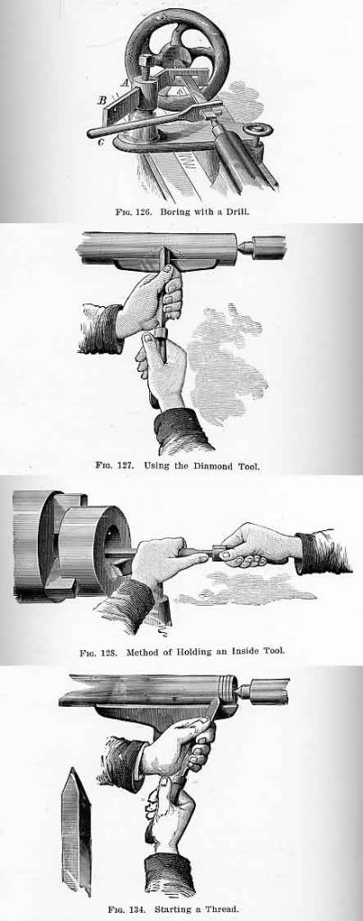
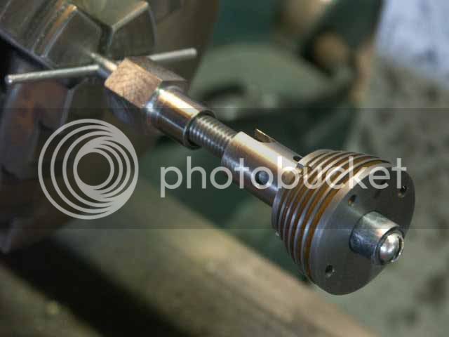
I tried various ways to contour the inside of the trumpet. My wood turning tools worked best! Although using hand held tools for metal turning made me feel like I was breaking some sort of rule, the illustrations below show that I was actually having an experiential history lesson.

Hand-heldmetalturning.jpg

These pictures are from the metal-working section of the book “Home Mechanics for Amateurs” by George M. Hopkins (1903), published by Scientific American. I bet my Grandpa learned to turn metal this way.

ContouringTrumpetemail.jpg

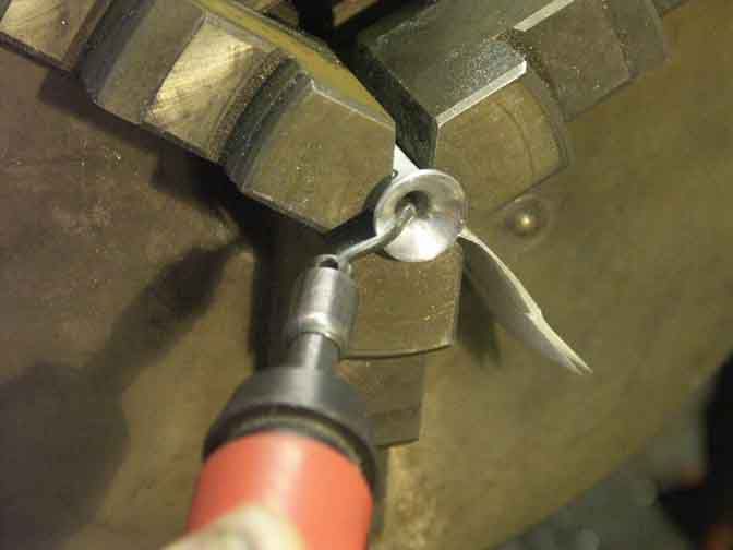
And the curvature of my deburring tool worked best to blend the inner-most radius of the trumpet.

FinishedExhaustStacksandNutsemail.jpg

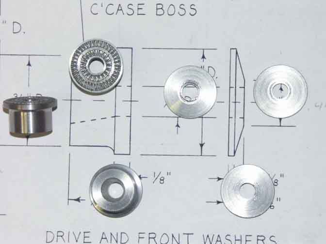
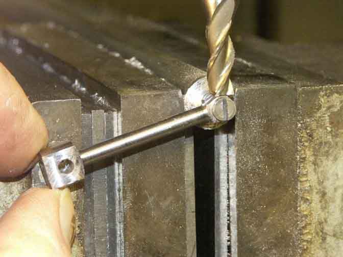
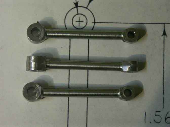
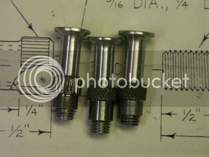
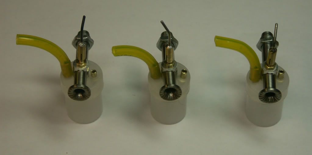
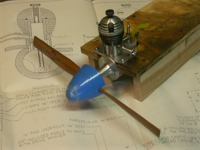
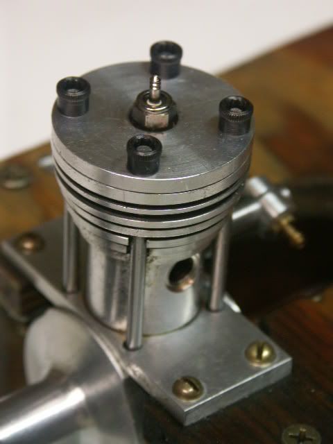
These are the finished exhaust stacks with nuts attached. I have not yet built the intake venturi and its nut, but they are fundamentally the same except for dimensional differences, and the venturi gets a cross-drilled hole.

Bob G
 
Pat J -

Thanks for your comments.

I have found that building three copies of this engine has taught me to think a little deeper about how I am going to build each part, and it has been a valuable experience in itself. I find I take more time with fixturing that allows rapid completion of the second and third copies - like a production shop on training wheels. I am barely beyond the beginner stage, but I decided on a previous engine that, especially for milling, the set-up time often exceeds the machining time, so building at least two copies of each part is good insurance in case I screw one of them up during a later operation. The first part is often just an experiment, but the third part sometimes shows that the success with the first part wasn't just a fluke.

I, too, sometimes question whether some of the tools I'm using should be saved for posterity, but, heck, they were made to be used, and I don't know of any museum that would curate them. I hope posting the histories on this site helps give them exposure to the people who would appreciate it.

Have fun building your five. I'd like to see them.

Bob G
 
Due to sleep problems, a much too cold garage, and, most recently, a pair of week-long backpacks in the Grand Canyon, I haven’t made an visible progress on the MLA Diesel since November - but I've been giving it a lot of thought.

I’ve deviated from the original plans quite a bit here because I didn’t feel confident that I could make that fuel tank well enough to prevent fuel leaking from the bottom seals, and I also incorporated a seat in the spraybar for the needle valve to close against. I simply took the design for the spraybar from the "Mate" diesel, and modified a few dimension to suit this engine, and to hold the snap-on lid of a small plastic bottle.

Spraybar.jpg

Drilling out the spraybar made for 1/4” brass hex stock.

SpraybarNut.jpg

Parting off the spraybar nut.

FinishedCarburetors.jpg

Finished carburetors.

I used 1/2 ounce Nalgene bottles for the fuel tanks (available from stores that sell backpacking equipment). A 35mm film canister could be used if a larger volume tank was wanted. The bases snap off cleaning. I’ve made the fuel overflow vent capable of holding a short piece of fuel hose to act as a rudimentary capacity limiter, if desired. Some of my "work" on this engine this winter was actually pursuing similar concepts down two or three deadend roads before I hit upon this idea.

Bob
 
Bob- Thanks for this wonderful build of a very interesting engine. I like how your setups are well
thought out and explained. I've been a machinist since 1976 and have developed a great interest in
"antique" machine tools. It amazes me to read some of the history of companies started in the 1800's and
recognize the names from machines and tools I have used. I love your "history lessons" and the use of your
grandfathers tools. Just last month I used one my grandfathers adjustable reamers to re bush the front
landing gear strut on a Lear jet, He would get a kick out of that. As far as using those tools, go ahead,
they're built to use and to last. I know they will be well taken care of.

Regards,
Mike
 
Excellent build thread. I need to take better pics. Thanks for the detailed descrition and history lessons. Nearly run time?

Brock
 
Great build thread. Lots of excellent photos. A picture is worth a thousand words
 
With all the major parts made, I've begun lapping the piston and cylinder of the first engine.

The attached photos show the major steps.

LappingPistonemail.jpg

The piston lap resembles a donut with a cut thru it. I machined it from a brass pipe plug, slit it, and embedded diamond paste. I used a hose clamp to control the diameter. I had already used the lapping directions and diamond lapping compound included with the MLA Diesel kit to successfully complete my "Mate" Diesel about a year ago. I've acquired another sample of diamond paste from a different manufacturer, so with an interest in experimenting, I used the new diamond paste first. The label on the new sample didn't give a grit size that I could compare with the original, but I found out real fast that the new stuff was much coarser, and aggressive to the point of being grabby. You can see the resulting surface finish on the piston. The MLA kit included a #30 grit compound, which is slower, but I think better suited for an engine this size, and results in a surface finish that is good enough to reflect the shapes of images, but not a mirror finish. I'll use it for the rest of my lapping. (Who knows - perhaps the slightly rougher finish on the piston may help compression sealing by giving a textured surface for the engine fuel to stick to.)

PartingoffPistonemail.jpg

When all of the machining marks had been lapped from the piston, I parted it off from its stub.


I made a hand-held ID lapping tool last year that incorporates a #6 taper pin to expand the lap. I wanted the lap to enter the cylinder from the crankshaft end so I could give it a slightest taper that ensure a tight fit right as the piston reached TDC, but the configuration of the cooling fins made it hard to grip the cylinder in the lathe chuck, so I held the lap in the chuck and held the cylinder by hand (carefully, in case the grabbed it).

LappingCylinderemail.jpg

Andy's instructions suggest imbedding the diamond into a copper lap. I didn't have copper, but by way of experimentation, I made laps from 360 brass, 6061 aluminum, and 50/50 solder. Not having lead, I thought of an easy way to cast a lead solder lap. I have a bar of 50/50 solder that my dad used to have, and I'd guess that it might be 60 years old or more. I've never needed it before. I happened to have a 4" long nipple of 1/2" steel pipe, I put a cap on it, and used the propane torch to heat it and fill it with molten solder. When it cooled, I put it in the lathe and carefully turned the steel pipe away - since the pipe was a little out-or-round, it could have been a little hazardous due to a semi-interrupted cut when the steel got thin. Then I drilled and reamed the solder with a #6 pin taper reamer to fit the lapping holder. First time I ever machined solder! After charging the brass, aluminum and solder with diamond, I remembered a trick I had learned in my photo darkroom. In the dark, it is often difficult to tell which side of the photo paper has the light sensitive emulsion. Your fingers aren't sensitive enough to tell the difference. But your lips can! In the same way, my fingers couldn't tell which laps held the most diamond, but my lips could tell that the brass held less diamond than the aluminum or solder, which were roughly equal and both worked better than the brass on lapping the cylinder. (Your mileage may vary.) Since the cylinder was approaching final size while I was using the aluminum lap, I ended up finishing the cylinder with the it. Since the aluminum lap is easier to make, it'll be my first choice next time (unless I get some copper to experiment with!)

With the piston and cylinder of the first engine lapped, it's time to begin assembly!

Bob
 
IT RUNS!

During assembly of the engine, I found some slight interferences between the connecting rod and crankcase, but these were easily resolved with a little hand work. A bigger problem presented itself when the cylinder studs didn't reach beyond the bottom of their recesses in the head, apparently too short! Many of the dimensions on this engine are given in 1/32 of an inch, and I encountered a "tolerance stack" here where all my dimensions were on the long side, except the studs. Plus, my paper gaskets may have been a little thicker than called for, and I may have drilled the holes for the studs a little too deeply into the crankcase. Anyway, by picking up a few thou here and there by reworking to the shorter end of tolerances, and deepening the recesses in the head, I got everything to fit properly. The crank rotated easily, except for a slight pinch as the piston hit TDC, just as intended. I had left the "spigot" of the cylinder head, which extends into the cylinder, intentionally long, so now was the time to trim it to provide the appropriate combustion area. With all the parts except the intake and exhaust stacks, I quickly fashioned a test stand to mount the engine to, and mounted a 12x6 propeller. I primed it with a few drops of fuel thru the exhaust port, underneath the cylinder into the crankcase,and flipped the prop. IT FIRED! This thing wanted to run, so I mounted the intake and exhaust stacks. Once fully assembled, this engine fired with the first flip of the prop! But it got dark before I could find the right combination of compression and needle valve settings for it to run.

But yesterday, I fiddled with the engine for about 5 hours. It would fire when primed, but it wouldn't run. I also discovered that the needle valves in two of my carburetors weren't seating properly, so the fuel flow wouldn't completely shut off, and the engine appeared to be getting too much fuel. The third needle valve seated properly, so I switched to that carburetor - but it still wouldn't run for more than a second at a time. Since my "Mate" diesel will never start by hand, I resorted to the "no-no" of diesel model airplane engines - an electric starter. In order to avoid breaking the engine due to hydraulic lock, I always prime with just a couple drops of fuel from a dropper (never choking) and always flip the prop 5 times by hand before using the starter. Even with this method, the engine would only run 1 second, then 2 second, then 3 seconds, and then 5 seconds at a time. At this point I considered that it was firing enough that I should put on my hearing protectors - and on the next attempt it took off and ran. IT RUNS! IT RUNS! IT RUNS! Oddly enough, once it got running, it would run over quite a range of compression settings, but it seems to like the compression screw two turns open, just as predicted in the instructions by Andy. My needle valve is set at 2 5/8 turns open, but it will also run about a half turn either direction. I ran about 5 half-ounce tanks of fuel thru it, using the props I had on hand - 12x6 and 11x6 (stunt) wooden props, and a 9x6 plastic one. It is my imagination that the 11x6 made the greatest amount of wind, so I've left that one on for now. It still won't start by hand, tho.

CompletedMLADiesel.jpg


I've posted a real short video on YouTube.

[ame]http://www.youtube.com/watch?v=BF82SY004m0[/ame]

This has been quite a nice little adventure and learning process, which will continue until I get the other two engines running, too.

And thanks, Andy Lofquist, for making this kit available, for your well written instruction booklet, and for your assistance via email and phone!!!!

Bob
 
Congratulations Bob. th_wav
Small compression ignition engines take careful and precise workmanship like you have showed in your excellent build thread. The fact that you got pops very early on in testing is proof.

I think many of us resort to an electric starter during the early days of debugging an new engine. I have even bent a rod or two in my time. They are OK if you take the proper precautions.

I have gotten lazy and use commercial laps, Acro-Lap, and just change the barrels for different grits. I use diamond for lapping also. I think that Enco has had the best price on the diamond paste lately, but I cant be sure. I tried to check but their web site is down this evening. Price really dees not matter too much as a 5 gram syringe will last for many years if you build a lot. For bores 1/2 inch and larger I have used #30, which is 30 micron. On smaller bores I follow it with 10 micron.

Gail in NM


After some time spent experimenting, I've been able to get my first of the three MLA Diesels to run at 5800 - 6000 rpm with a 12x4 propeller. Being a long stroke engine, and having the piston shorter than the stroke, causes it to have a lot of sub-piston induction. This allows the crankcase to suck in more air thru the exhaust port, but limits the duration of intake port timing. I found that removing the exhaust stack increased the rpm from 4800 to 5800. Shortening the intake venturi also increased the rpm. This required changing from an integral fuel tank to a remote tank. The engine was generating enough power to take flight, so I sent it to my brother-in-law in California. He builds superb old-time style freeflight planes. He mounted it on a "Perris Special", and I made a trip from Salt Lake City to be there for the first flight.


[ame]http://www.youtube.com/watch?v=-7gaRNHXCSA[/ame]

We had 5 flights that day. The first engine run was 15 seconds, and we gradually increased this until the last flight had a 70 second run, and a flight time of about 135 seconds.

Since my house is at 4700', and my brother-in-law's house is at 100' above sea level, we had to decrease the compression by two complete turns of the adjustment screw - much more than I would have guessed.

The MLA Diesel proved to be a very versatile design, and great for experimentation. I was having so much fun with it that I converted my second engine to a glow engine (my first glow engine), and then re-converted that to a gasoline spark ignition engine (my first spark ignition model airplane engine).


MLA Diesel converted to Glow Ignition
PICT0015.jpg


MLA Diesel converted to Spark Ignition
MLAIgnitionjpg.jpg


Bob

 
how is it running on spark? are you still using glow fuel or 2 stroke mix
 
Don't cut fins the plan doesn't call for in the head as this influences ignition timing.
Low rpm = cooler head = retarded ignition.
High rpm = hot head = advanced ignition.
 

Latest posts

Back
Top