miniature model flight simulator

Home Model Engine Machinist Forum

Help Support Home Model Engine Machinist Forum:

This site may earn a commission from merchant affiliate links, including eBay, Amazon, and others.
Hi Hobby,

Interesting project! I am curious to see if the cylinders without o-rings will work. I have some plans already for years for making a small press-brake machine (not for use, just to put somewhere). Do you have an idea already for the hydraulic pump unit and the kind of pressures you need to move the cylinders?

Keep on the good work!

Have fun, Jeroen
 
Hi Jeroen,


Here is a example build I did a few months back with a hydraulic cylinder build, I did not use any o-rings, I was able to get good compression, but for this application it worked fine with no o-rings.

I used 3 in 1 oil, for the hydraulic fluid.

The last part of the video, I'm lifting a set of 1-2-3 blocks

http://www.youtube.com/v/jd7xknZruyE&hl=en&fs=1

For your application, you may need o-rings if your building a bigger cylinder and need more pressure, my builds are very small cylinder bores, and this simulator project is going to be a very light load, mostly the simulator unit itself will be made out of balsa wood or something very light, so the pistons won't need much pressure to work.

The pump unit will be, probably like in the video, a manual piston cylinder unit.

 
Hi Hobby,

Cool! There are so many nice things to build, wish a day had 48 hours! I can easily write 3 A4 papers with projects I want to do.....

Maybe you find this site interesting, its in Dutch but the pictures explain enough.

http://members.home.nl/chof/Modelhydrauliek.htm
http://members.home.nl/chof/Cilinders.htm

This guy made a real working hydraulic digging machine. I am eager to start to do something with hydraulics, but I think it will be at least a year from now. I first want to finish the Stuart lathe and my Stanley car. But I will follow your progress closely :)

 
Thanks for the saw info. I like the lathemaster version, but i am still undecided as to what to buy. Each time i have to hacksaw thru some stock i think i need one! ;D

 
coopertje said:
Hi Hobby,

Cool! There are so many nice things to build, wish a day had 48 hours! I can easily write 3 A4 papers with projects I want to do.....

Maybe you find this site interesting, its in Dutch but the pictures explain enough.

http://members.home.nl/chof/Modelhydrauliek.htm
http://members.home.nl/chof/Cilinders.htm

This guy made a real working hydraulic digging machine. I am eager to start to do something with hydraulics, but I think it will be at least a year from now. I first want to finish the Stuart lathe and my Stanley car. But I will follow your progress closely :)

Thankyou for the links.
By the way, your doing a realy nice job on your stuart lathe and stanley steamer.
Keep up the great work..


Diy89,

Your welcome,
I find for small hobby work those benchtop models are real handy.

--------------------------------------------------------------------------------------------------------------

Hello everyone,

I had a whole nice write up with about 10 pics. discussing my progress in this today, but accidentally deleted the pics from the camera, before they were transfered to my folder.

So in short
I want to put a decorative design on the cylinders, so I made a form tool and tested it out on a scrap part here it is after machining.

129.jpg


I will work on this to make it better and maybe use it on the cylinders.


That first form tool was made quickly as a proof of concept, now that I see it will work, I made a new one, and took my time to make it right, I started out with a 1/4" X 1" wide steel bar. the kind you get (from lowes hardware store)

130.jpg


Then I machined the thickness to around 1/16" for the blade of the form tool.

131.jpg


132.jpg


Because I need 40 thousandths, depth of cut, it would be hard to draw this freehand, so I used my cad to print out a shape that can be used as a template to paste onto the formtool blank...

134.jpg


Using a dremel to shape out the formtool blank.

136.jpg


Then some relief sanding on the bottom side to give it a sharp edge, these form tools are more or less scrapers to scrape a form into the soft material (aluminum). So no need for hardening them.

137.jpg


A trial on a scrap piece.

138.jpg

IMG]http://img.photobucket.com/albums/0603/ddkiz/model%20flight%20simulator/139.jpg[/IMG]
140.jpg


Now one more trial run, this time on the prototype cylinder, to make sure it does not break through the internal bore.

Make 2 arbors to screw onto both ends, one for the chuck and the other has a taper hole on the other end, to fit into a live center.

141.jpg

142.jpg


Using a magic marker to allow me to know when the form tool has full contact with the workpiece, when finished.

143.jpg

144.jpg

145.jpg


Ok it works good on the prototype.

146.jpg


with the other protoype parts dry fitted for clarity of parts placement.

147.jpg


Ok time to do the real cylinders, for the project build.

148.jpg

149.jpg

150.jpg

151.jpg


All the parts made to date.

152.jpg


Have a great day...
 
This is a real education you're giving us, Hobby. Thanks for documenting this so well.

Chuck
 
Chuck,

your welcome,
and Thankyou for the complement.
-------------------------------------------


I got all the pistons and shafts machined and assembled, then I started working on the top endcaps for the cylinders.

Since no hoses will go at the top, there is nbo need for any gaskets to go at the top, so I made the top endcaps out of 2 pieces, one is a internal threaded ring, the other is an external threaded retainer, assembled together, to form one unit.

The outer ring was given some fancy triangular shape, using my indexing jig, on the mill.

154.jpg


then cut to rough length on the portable band saw.

155.jpg


drilled and tapped to fit the cylinder thread.

156.jpg


157.jpg


And then the top retainers roughed out

158.jpg


fitted to rings, and machined to length, then roundover profiled.

159.jpg


160.jpg


161.jpg


162.jpg


Here I'm trying out my new toy,(tool), microflow coolant system.
works nice.

163.jpg


here it is as a kit, put together, ready for use.

168.jpg


Now the endcap units are screwed onto there cylinders, then the cylinders are gripped in the lathe, so if the endcaps are crooked, the hole through the top will still be concentric with the cylinder bore. That's whats important, the endcap can be off a little, but the thru hole must be in line with the cylinder bore.

164.jpg


165.jpg


The assemblies to date.

166.jpg


I picked up some enamel paint from the crafts store yesterday, and tried it on a scrap of aluminum, to see if it will stay on, and it stays on real good, hard to rub it off, this paint is good for metal, as well as ceramics and stuff..

167.jpg


So I will try to paint these pieces, to give it more of a model look, just to make it more creative,
after all I'm not trying to make an exact copy of the flight simulator, but making a creative model of the concept of the flight simulator picture.

Thanks for looking in...
see ya later...


You seem to have mastered the form tooling Hobs. Great work, there is plenty of inspiration in your thread.

Kel
 
I recognize that coolant tank :D :D Great use for it!
 

Hi Kel,
Thanks for the encouraging words.

Hi Shred,
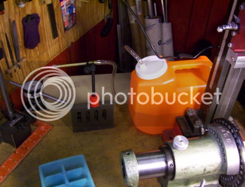
The microflow system seems to work pretty nice, I'll use it mostly for extensive cutting on the mill and lathe.
----------------------------------------------------------------------------------

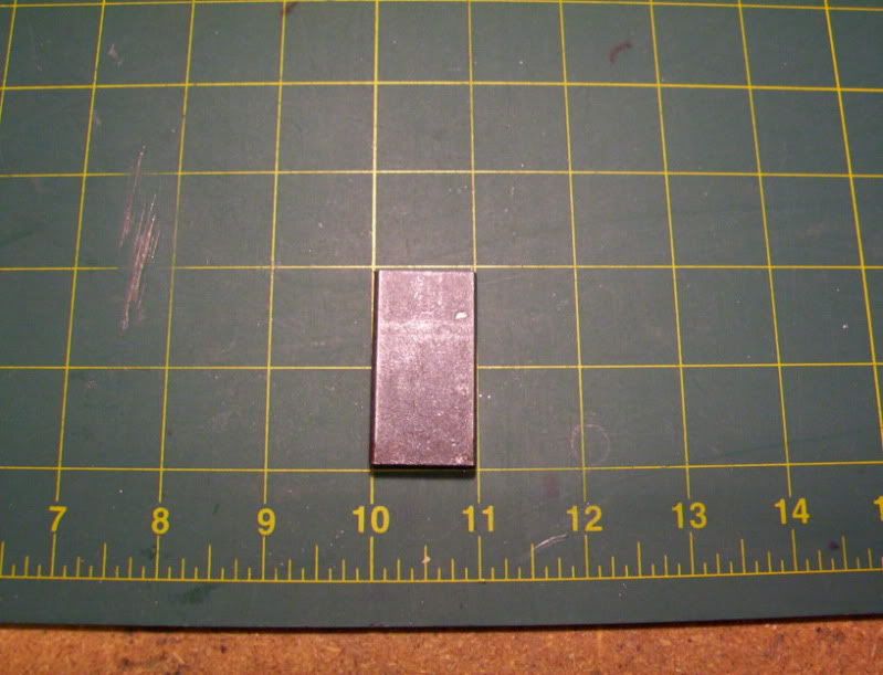
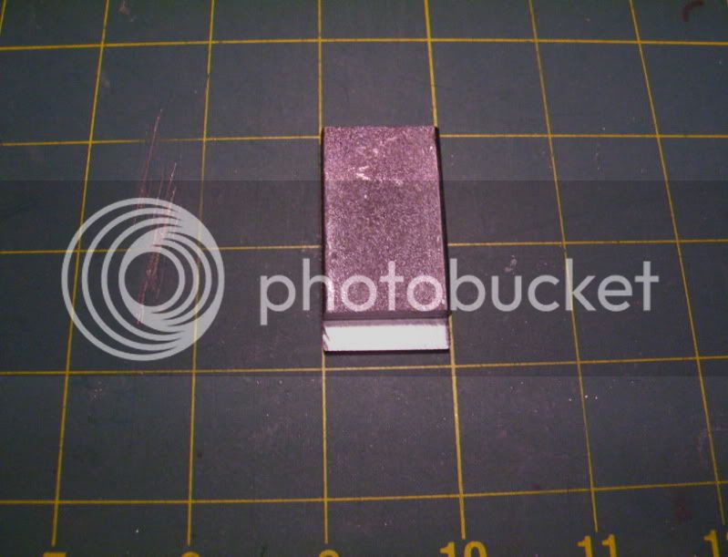
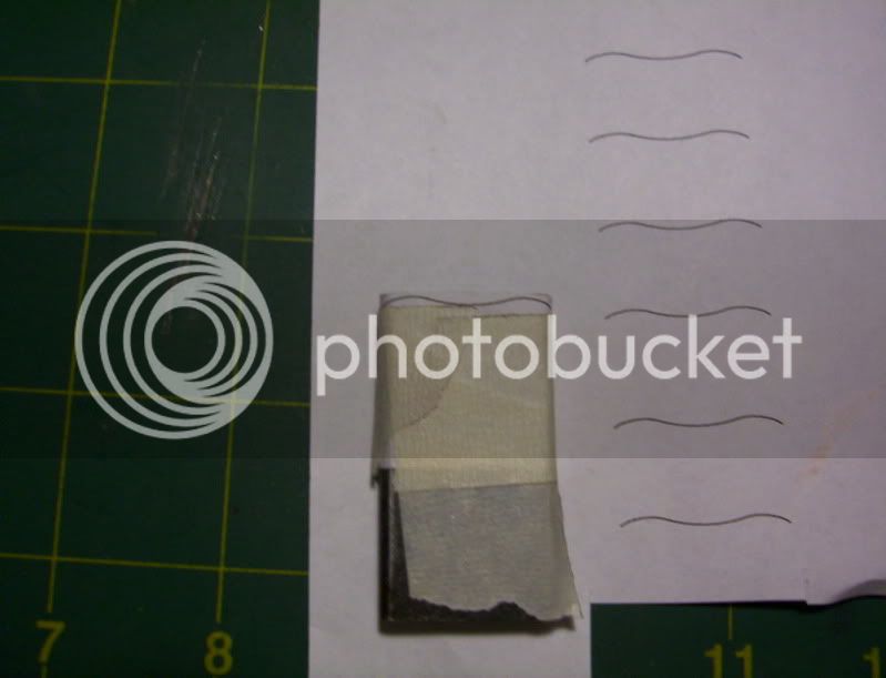
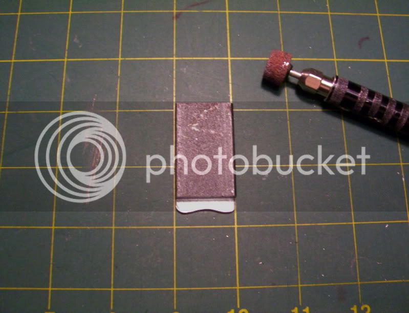
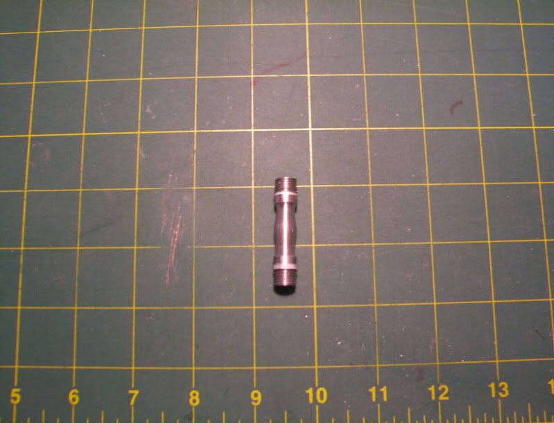
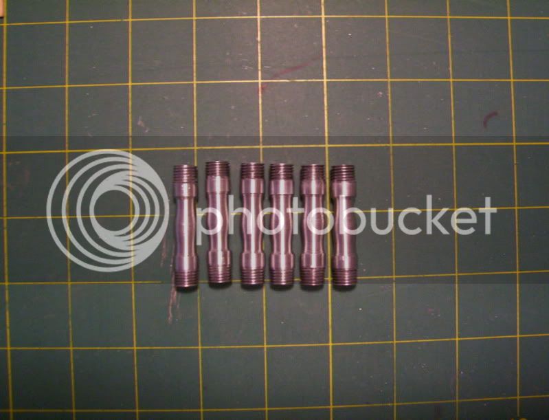
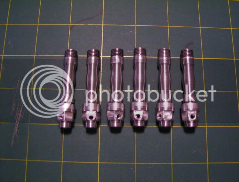
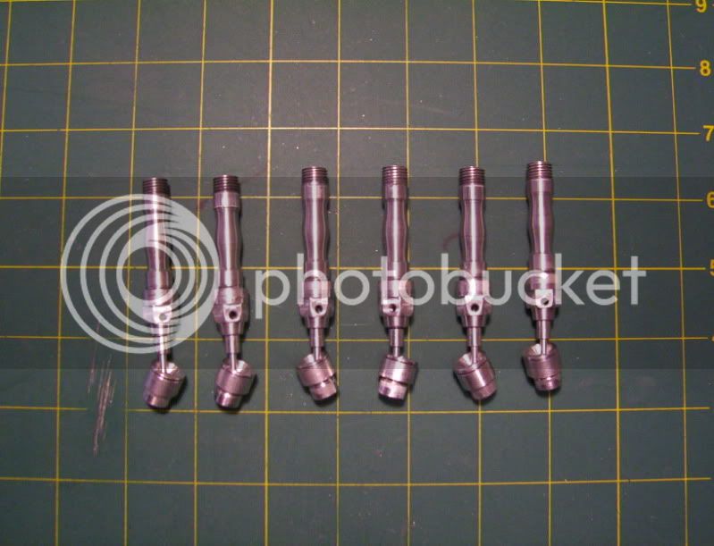
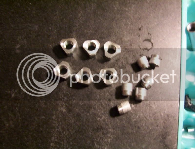
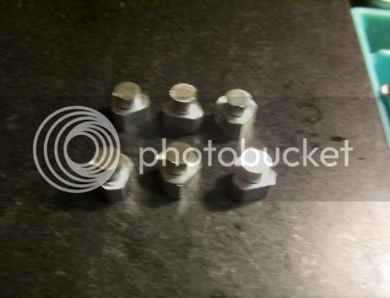
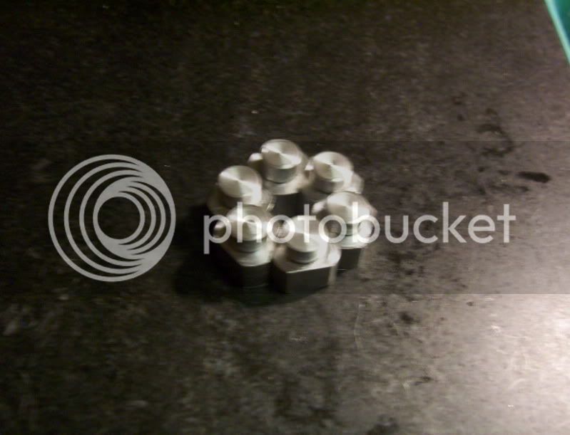
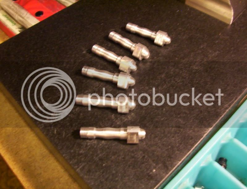
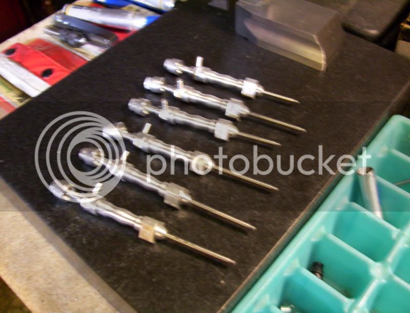
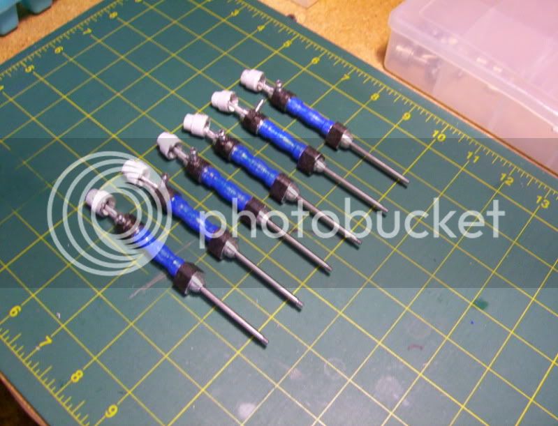
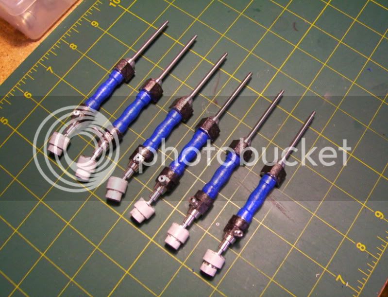
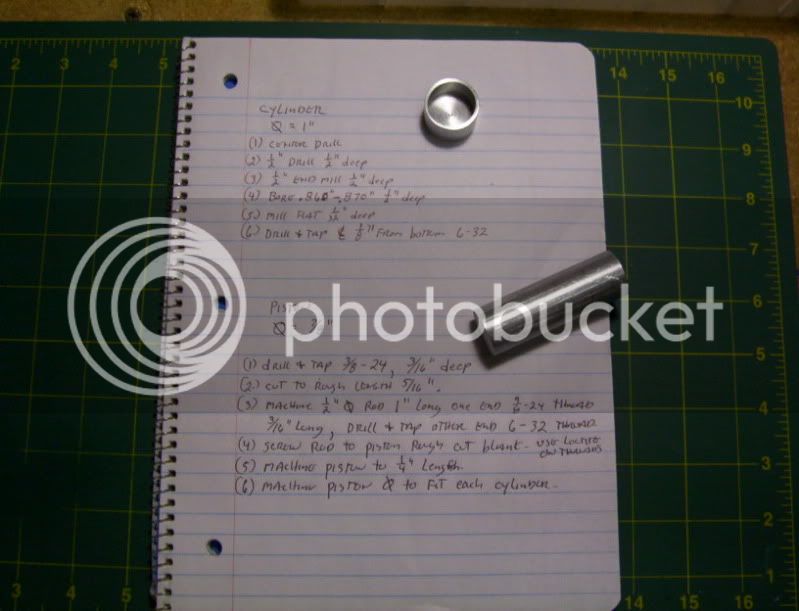
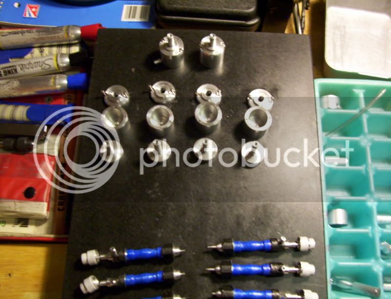
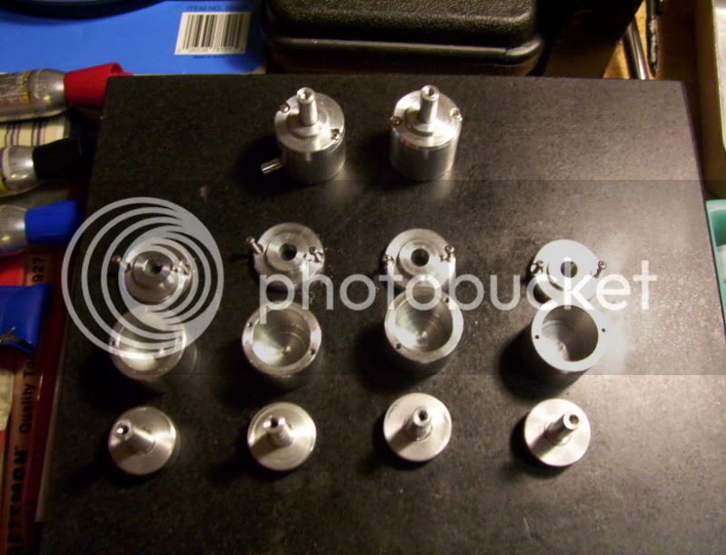
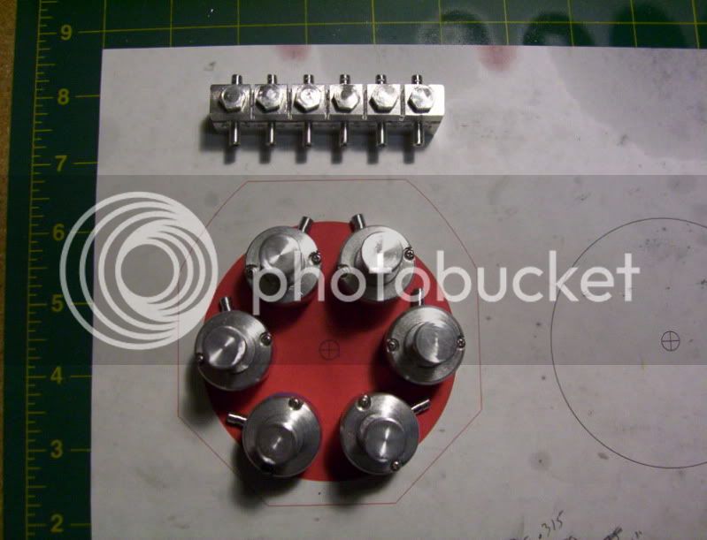
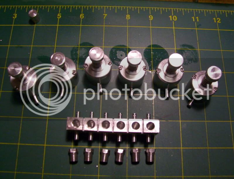
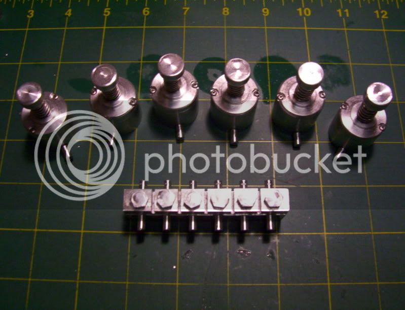
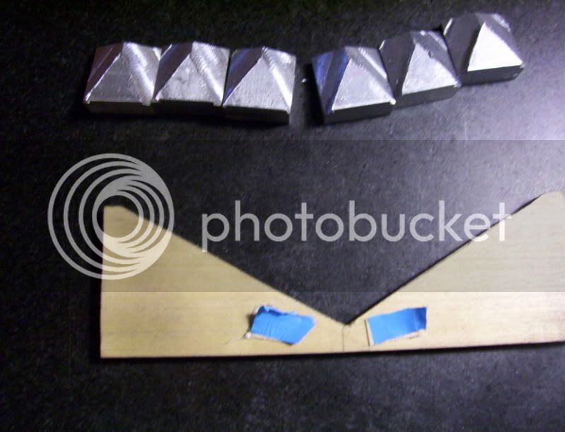
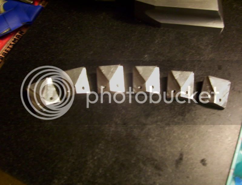
Here are the parts to date, with some paint slapped on them.

169.jpg


170.jpg


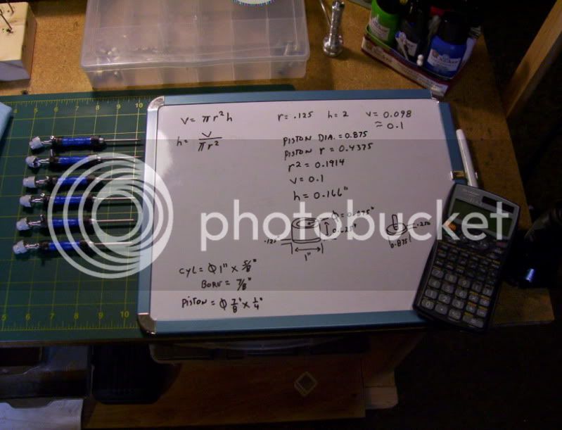
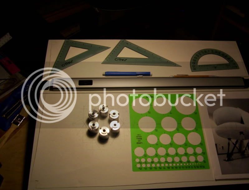
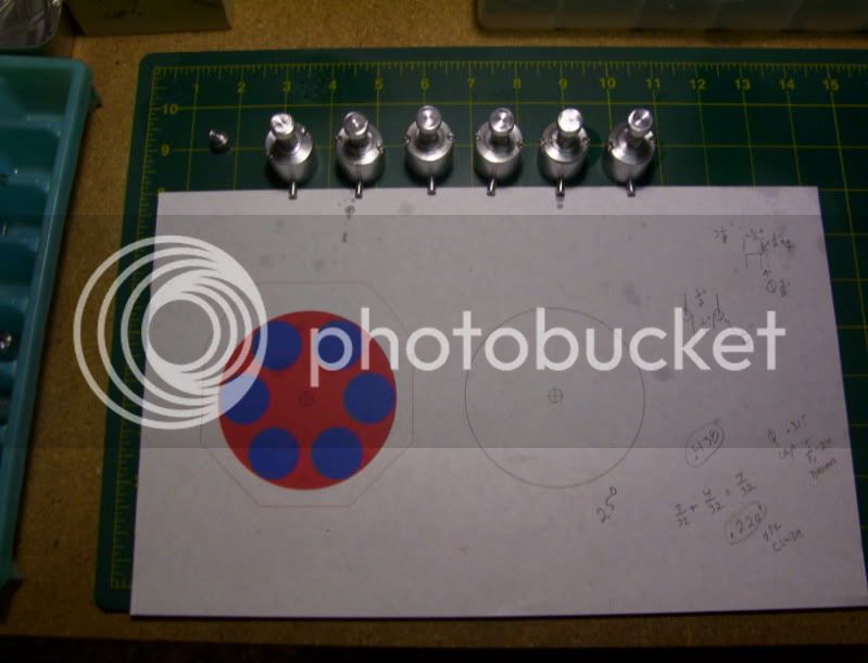
Now some calculations, to figure out the height of my driving cylinder needs to be with a 7/8" inner bore dia.

171.jpg


5/8" overall height should work for this.

172.jpg


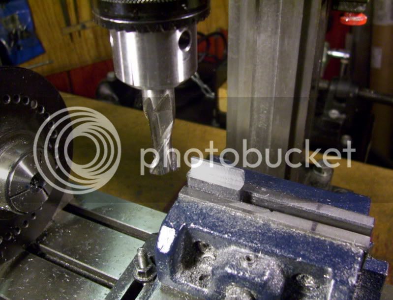
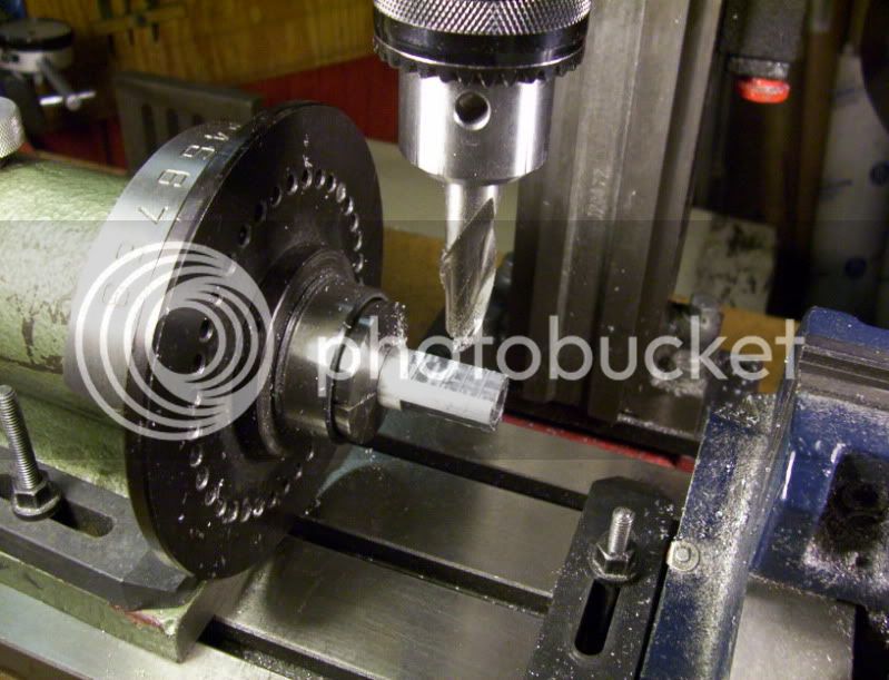
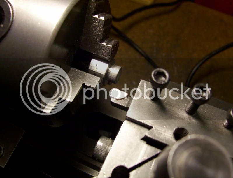
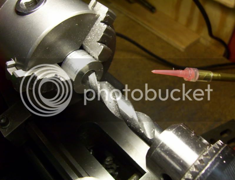
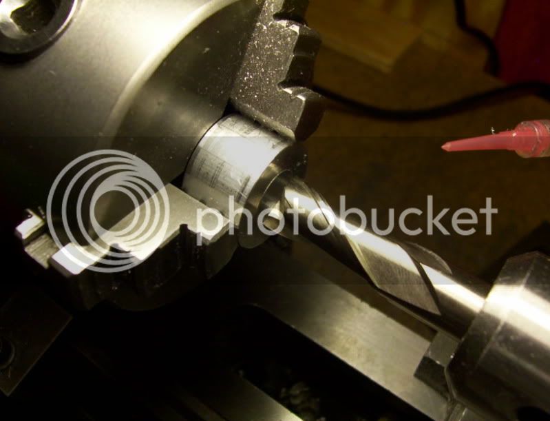
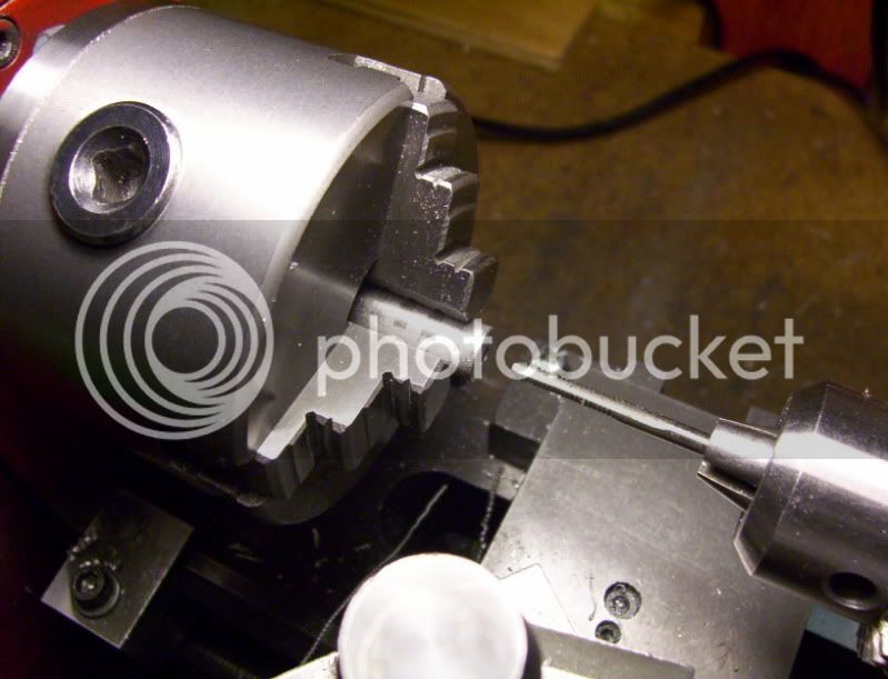
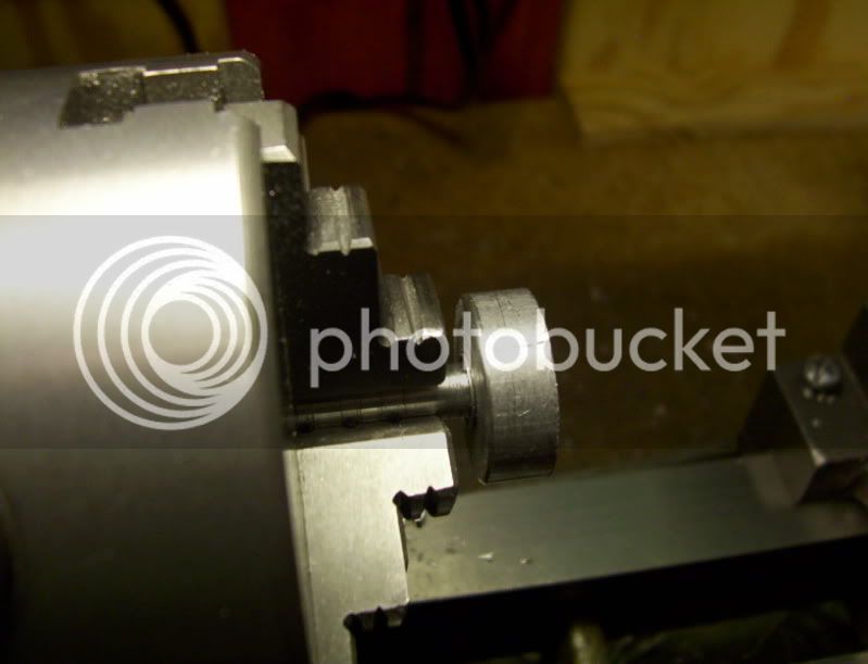
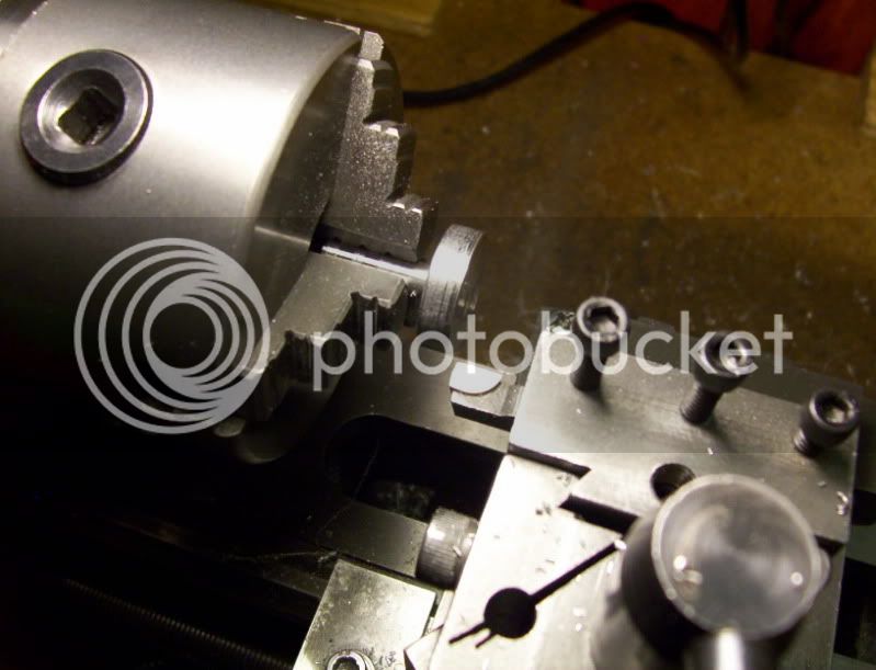
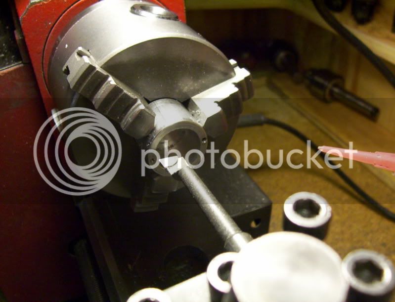
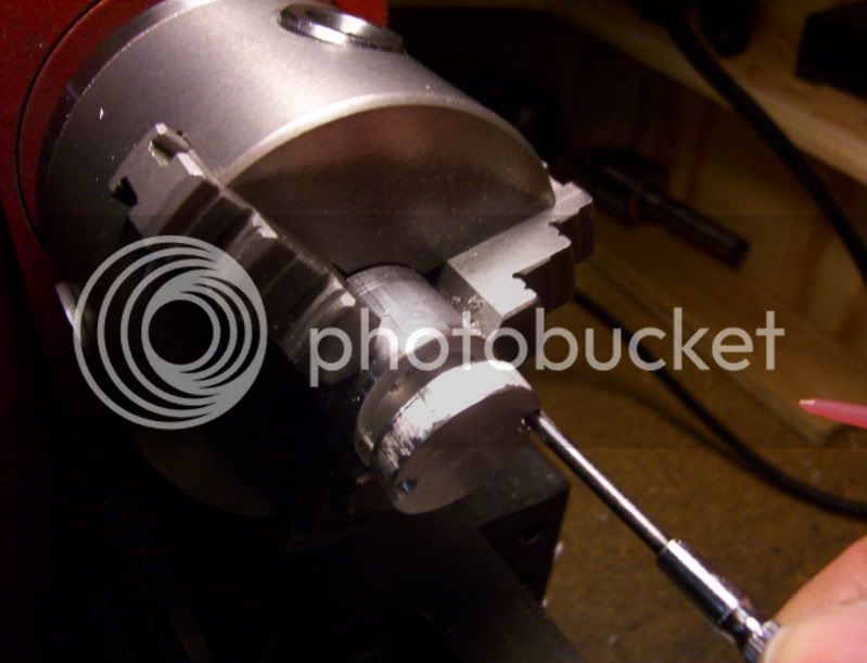
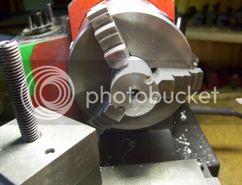
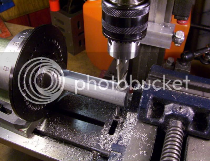
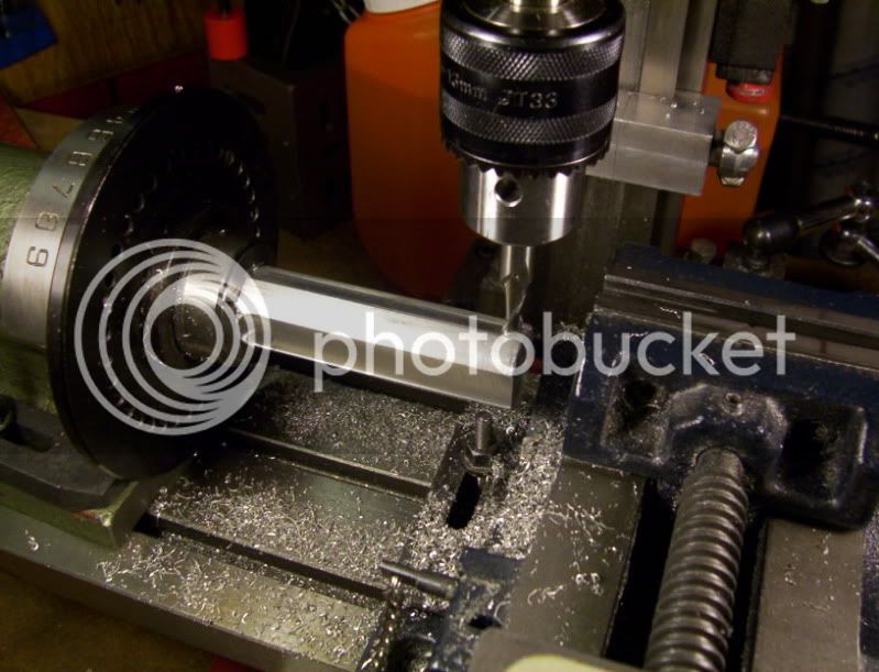
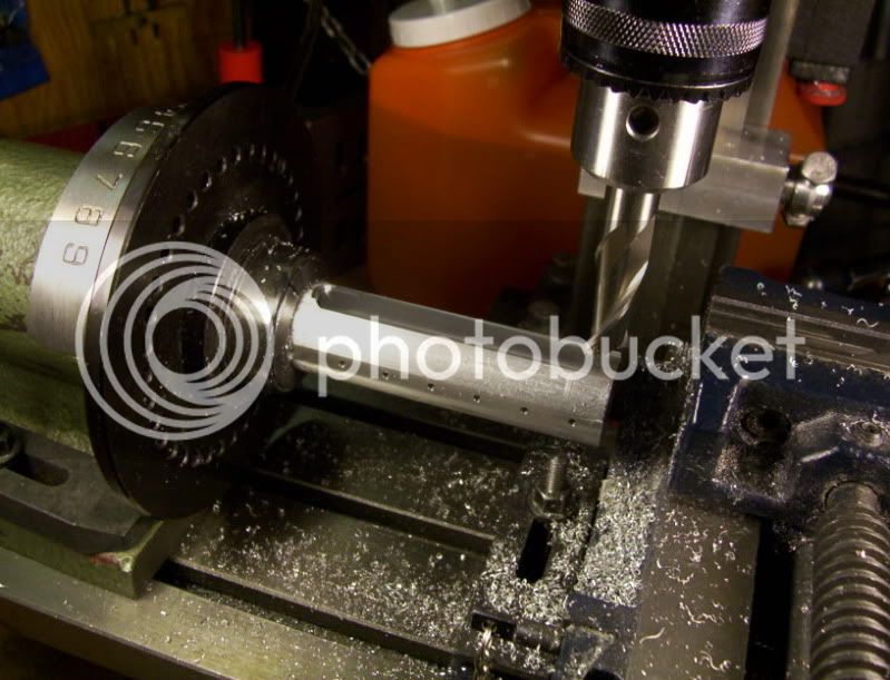
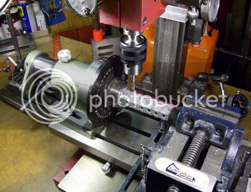
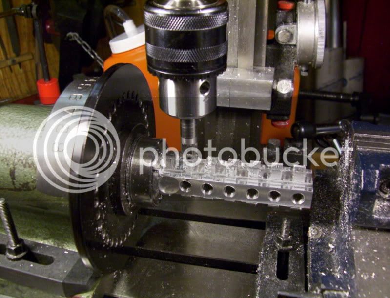
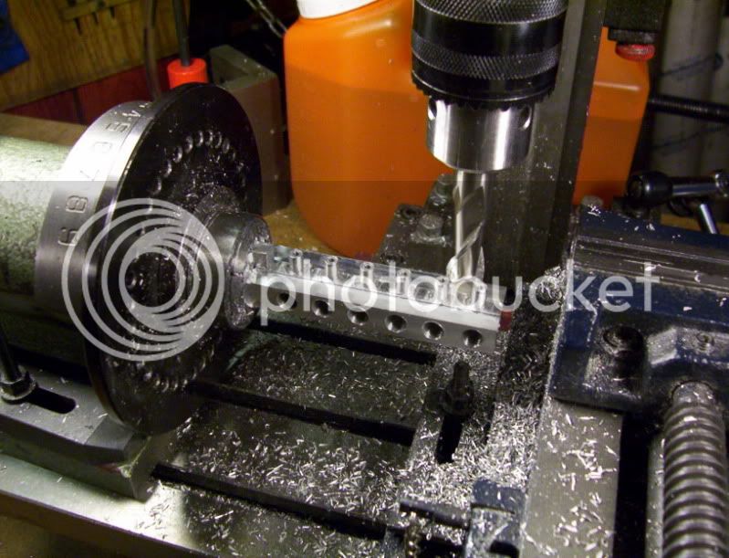
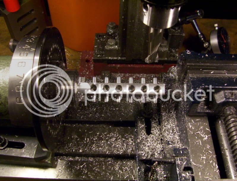
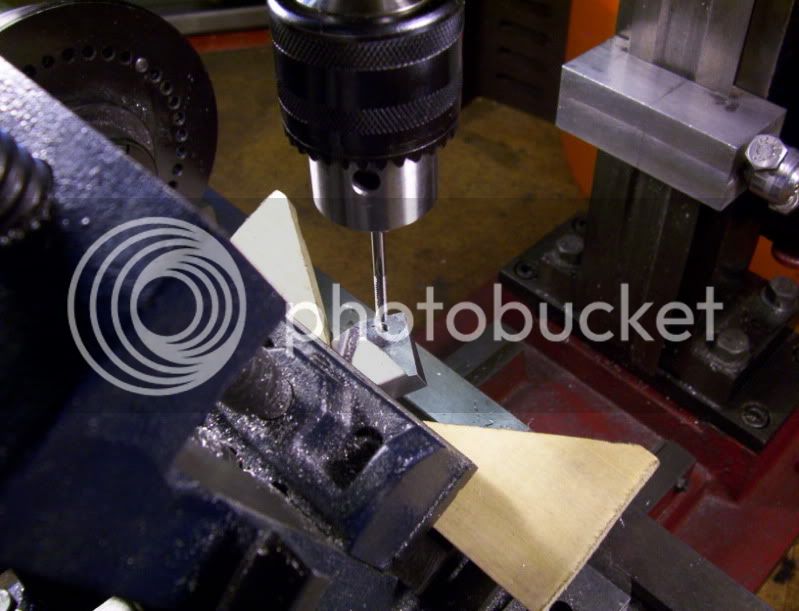
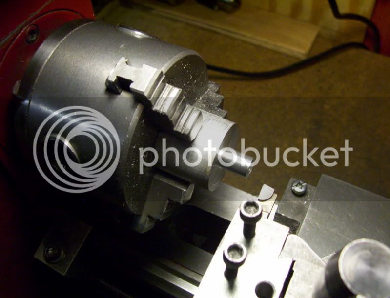
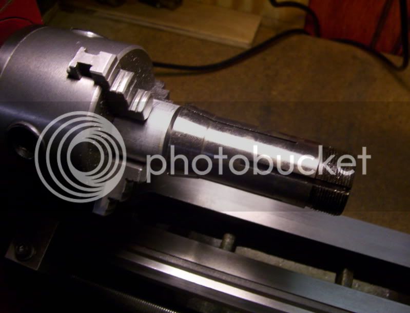
I drill with a 1/2" bit for a 1/2" depth to get started on the inner bore, for the cylinder.
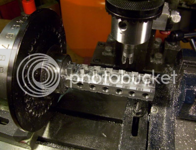
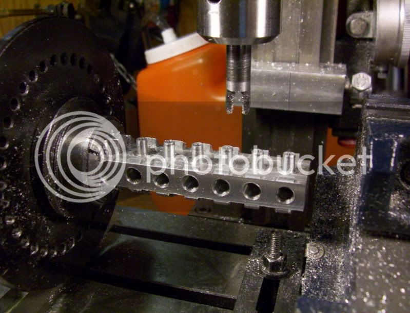
then I use a 1/2" endmill, to cut a flat bottom in the cylinder at this stage, of boring.

173.jpg


174.jpg


Then move to a boring bar to finish the bore dia. to around 0.86" - 0.87".

175.jpg


176.jpg


Time to go get something to eat, machining makes me so hungry all the time.

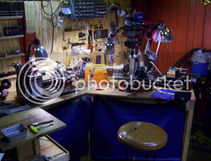
Well after watching a little DIY on television, while eating, I come back to see this mess, in my shop, while I was in here working I never noticed how messy and crouded it was getting with all the tools I kept bringing out.

BUT walk away and come back fresh and I see the difference now. I have a small shop area, in the basement.

177.jpg


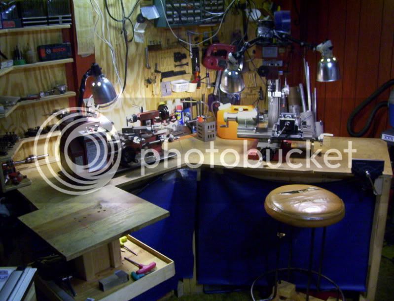
Now this is better, I can now move onto the next part of my machining session.

178.jpg


Since I need to make 6 of these units, I better write down the procedures.

179.jpg

--------------------------------------------------------------------------------------------------------------------------------

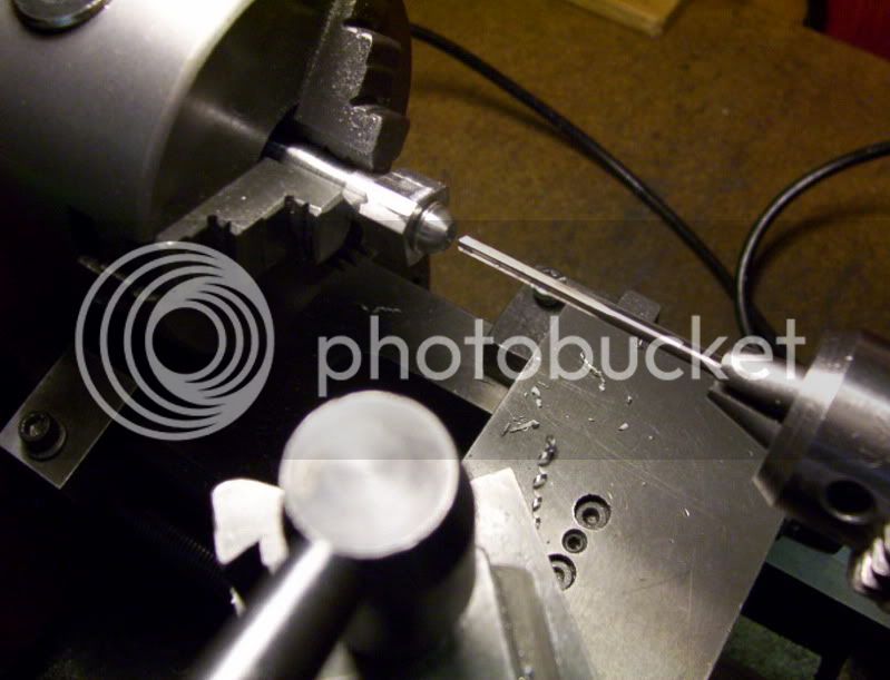
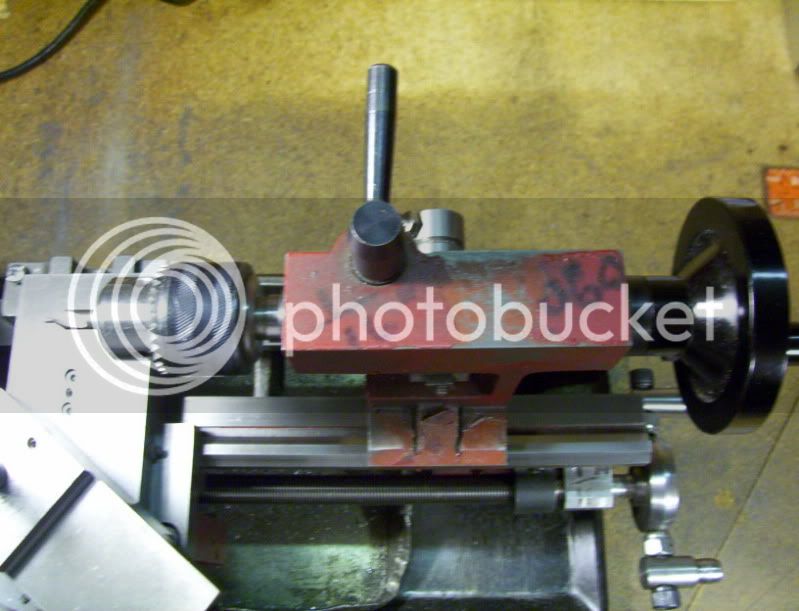
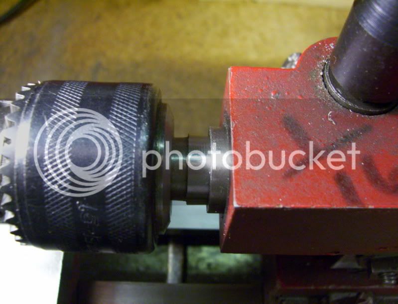
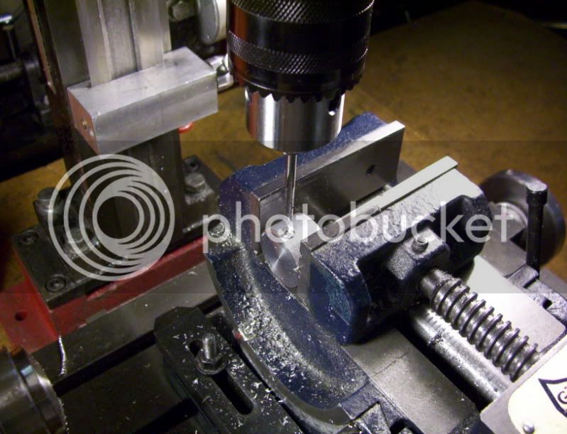
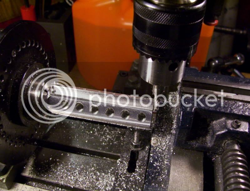
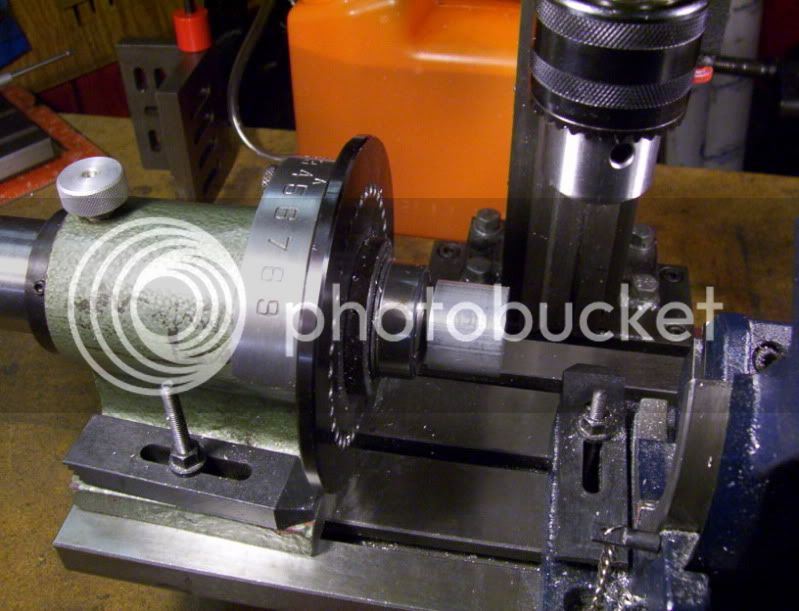
Here is a good tip for beginners.

If you need to drill a rough depth, without using a dial indicator, then test how far your drill chuck travels in the tailstock for one revolution of the handwheel. Mine is around a 1/16", roughly.

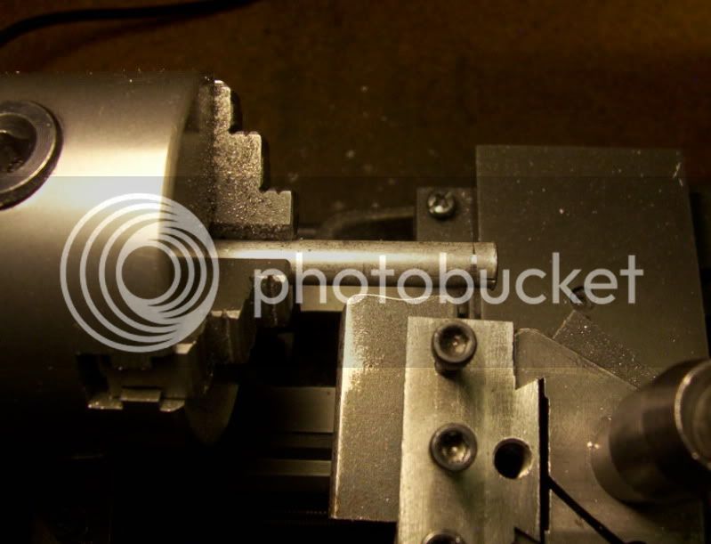
Then put the drill (center, jobber, reamer, endmill), in the chuck and crank the handwheel all the way in,

180.jpg


then make one turn of the handwheel out to advance the drill bit,

181.jpg


from there slide the tool bit up tight against the workpiece, and lock down the tailstock.

182.jpg


Then crank the handwheel back in till it stops, and start up the lathe
and then when you crank the handwheel back out to advance the drill bit, it will again touch the workpiece and that is now your reference of where to start your depth of cut, from there you turn the handwheel as many turns required to get to the depth you desire.

183.jpg


-------------------------------------------------------------------------------------------------------------------------------

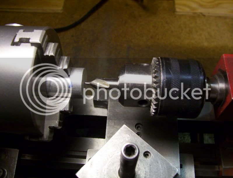
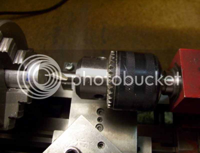
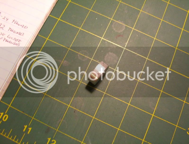
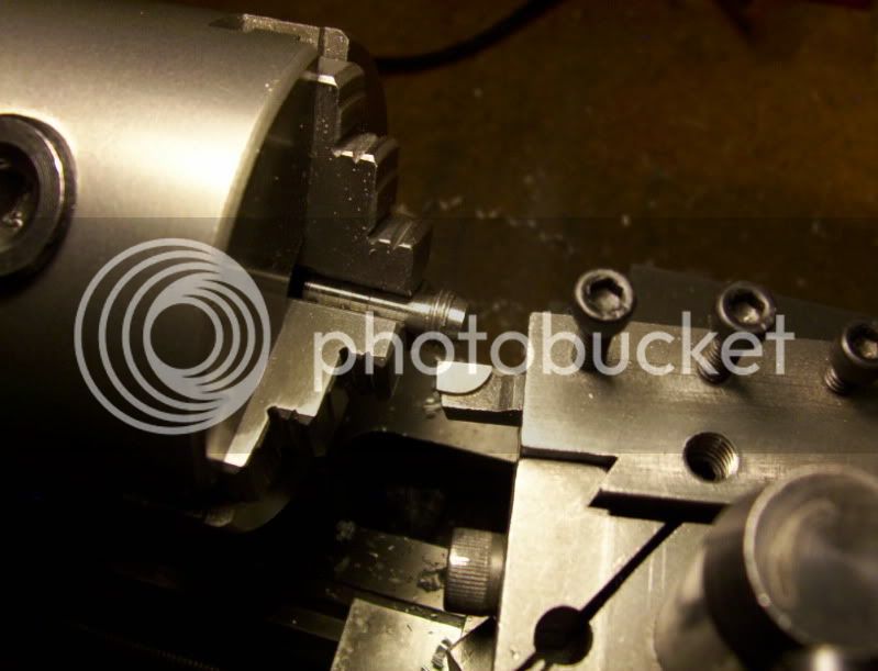
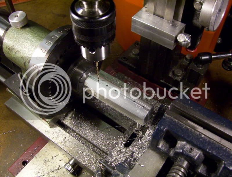
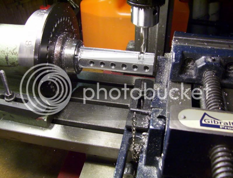
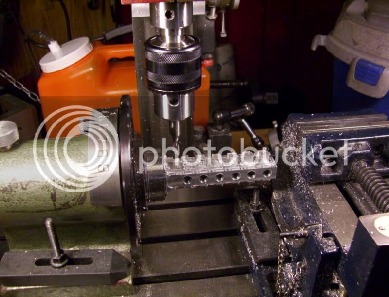
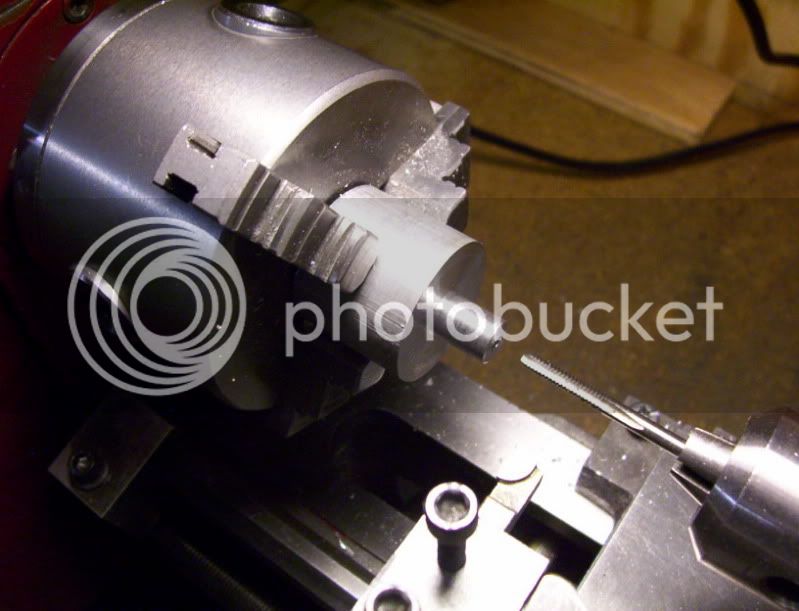
Ok that above procedure was done to drill a shallow depth of 3/16" using a drill for a 3/8-24 tap.
Into the piston head, so a piston rod can screw into it.

184.jpg


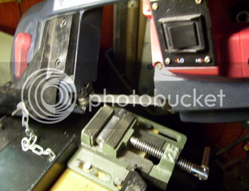
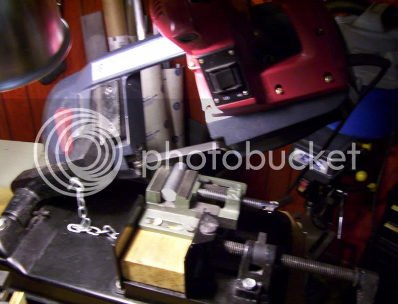
Now after tapping the blank, I cut it off at a 5/16" length using the benchtop bandsaw. (very quick way to cut a workpiece)

185.jpg


Nice accurate clean cut using this saw.

186.jpg


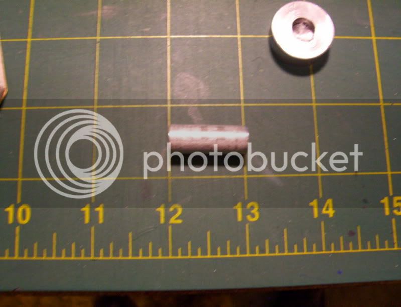
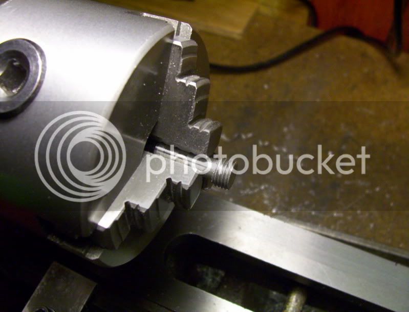
Now I cut a piece of 3/8" dia. stock to a little over 1", to become the piston rod.

187.jpg


After facing it to proper length then a hole is drilled and tapped to 6-32, at one end.
By drilling and tapping this hole allows me to use it in lining up the workpiece in the chuck jaws when a small grip is needed.

188.jpg


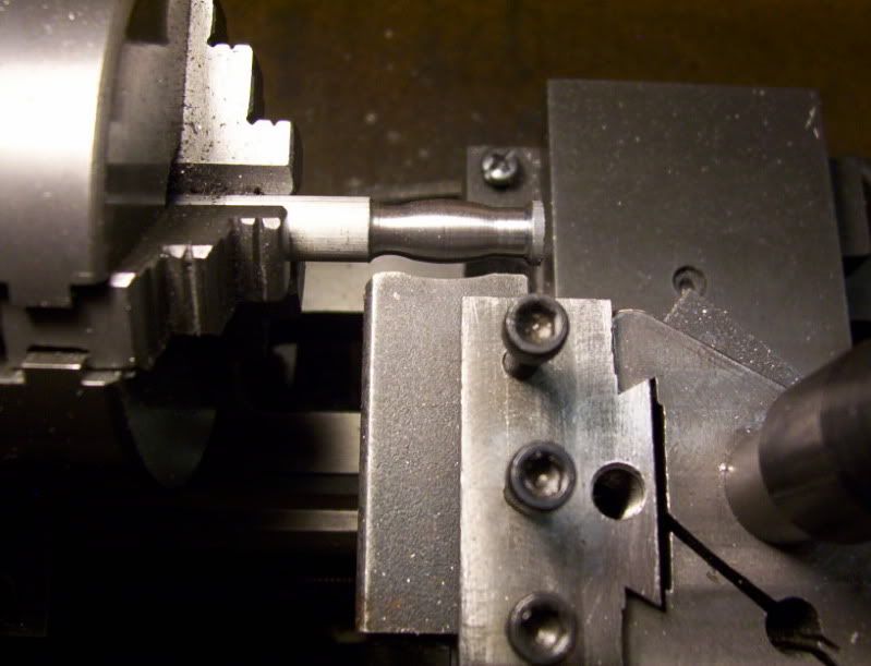
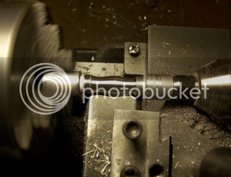
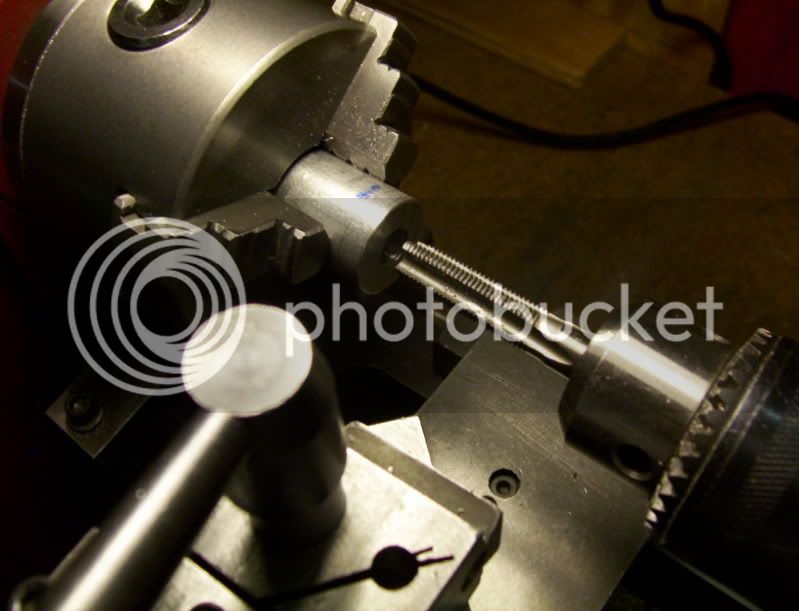
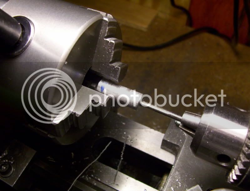
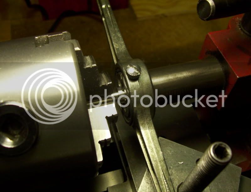
Now the rod is machined to a 1/4" dia. leaving 3/16" left at the originaql 3/8" dia., which is gripped in the chuck jaws.

189.jpg


192.jpg


Now the rod is turned end for end, and the last bit is machined to around 0.360" dia. so a 3/8-24 die can be used on it for threading.

193.jpg


194.jpg


195.jpg


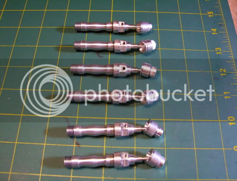
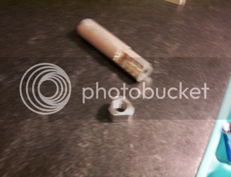
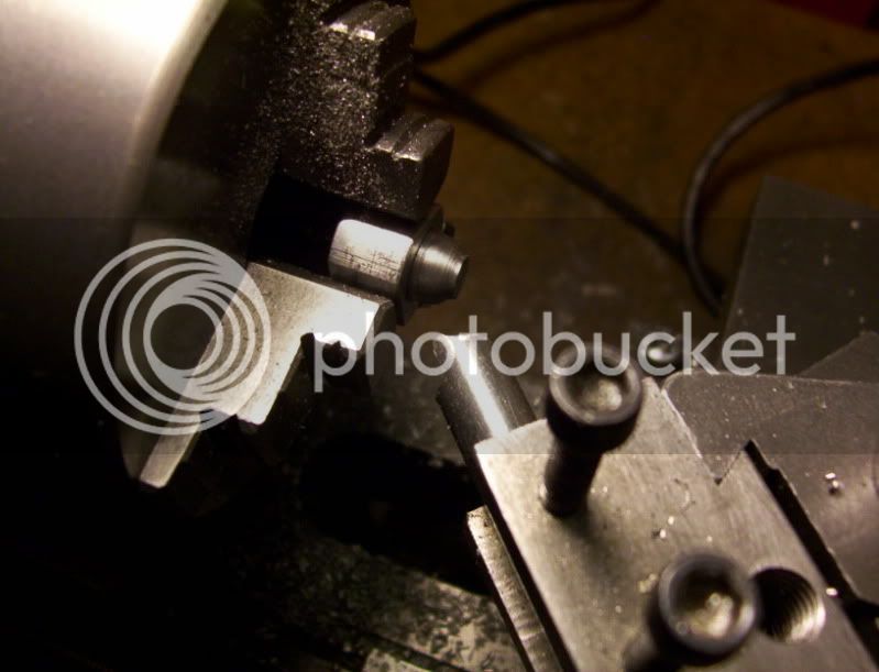
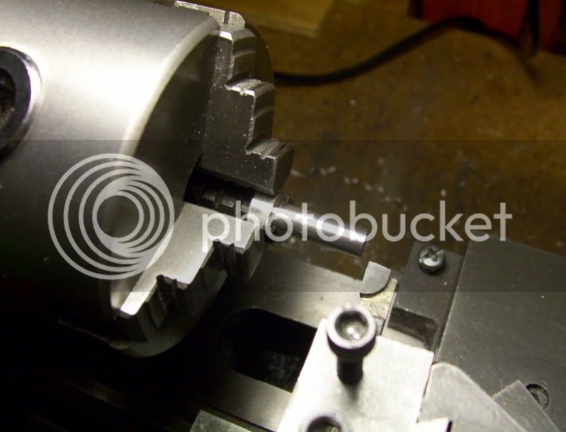
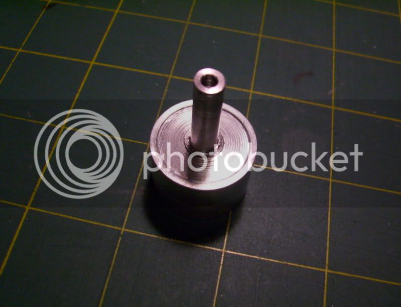
Now the roughed out piston head blank is screwed on tightly, to see how much thread is revealing. The reason for the thread on the rod revelaing is because I don't have a bottoming tap for tapping the piston head, so about 2 1/2 threads are really engaging.

196.jpg


But this is a blessing in disguise, because now I need to machine a taper at the bottom of the rod, taking off enough threads to leave about 2-3 threads left, by doing this it gives the piston head a really tight snug fit, with a pair of channel locks to make it tight without needing to use any loctite glue.

197.jpg


198.jpg


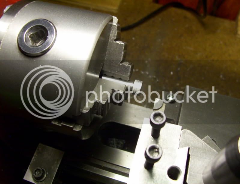
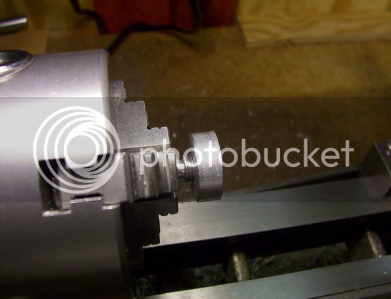
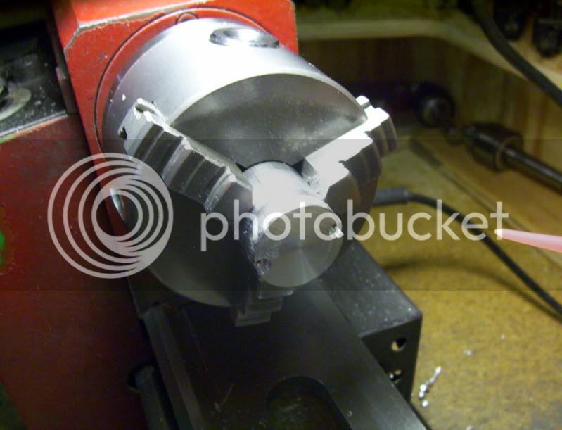
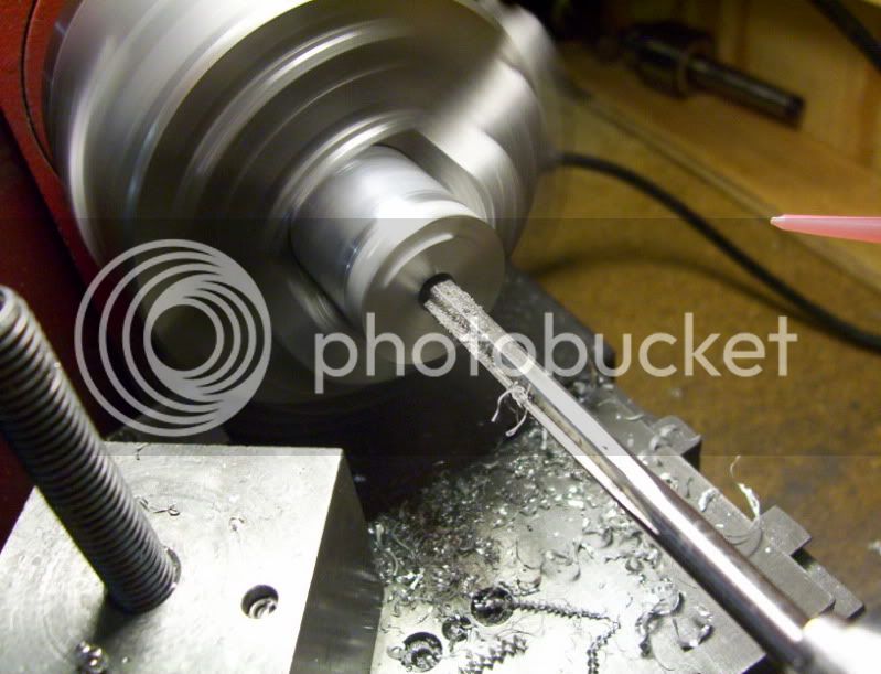
Now with everything tight and secured, I can machine the piston head to the proper length and dia. to fit the cylinder bore, it's being made for.

199.jpg


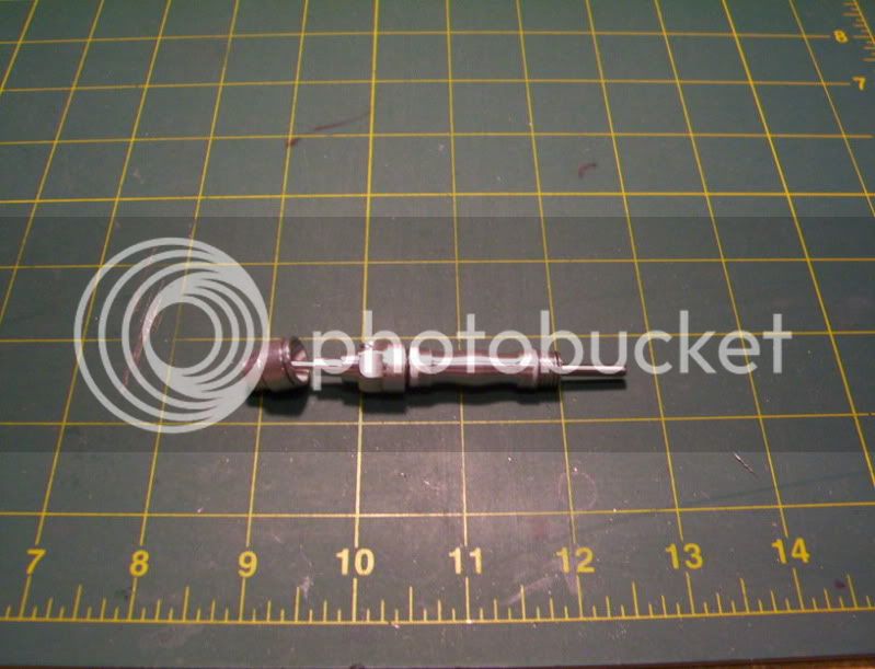
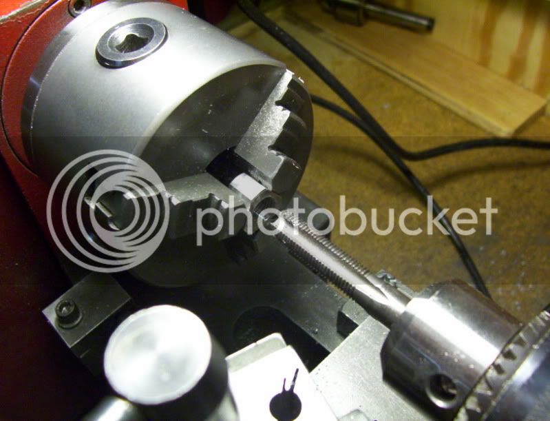
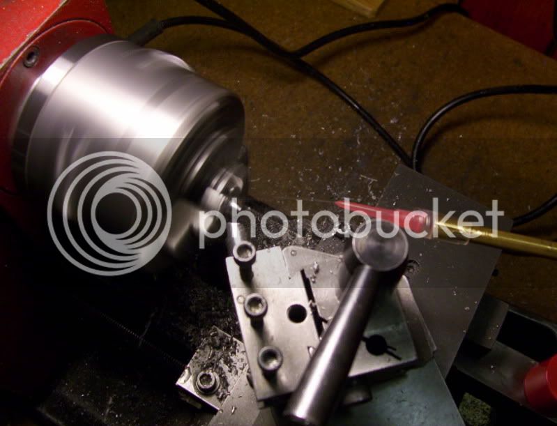
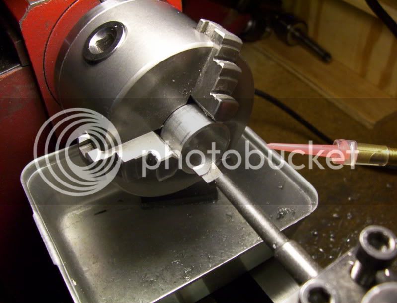
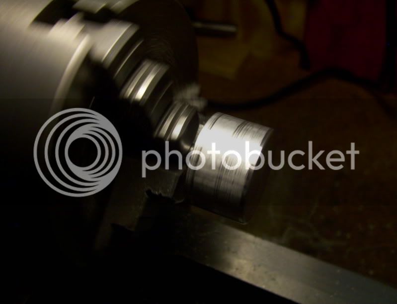
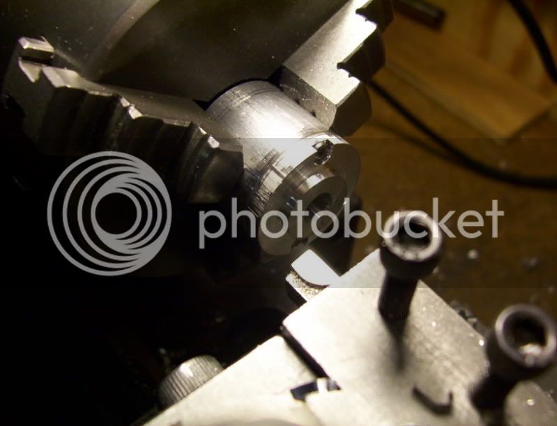
Cylinder fitted over the piston, and the chuck spinning to see how concentric and properly fitted the piston is inside the cylinder.

200.jpg


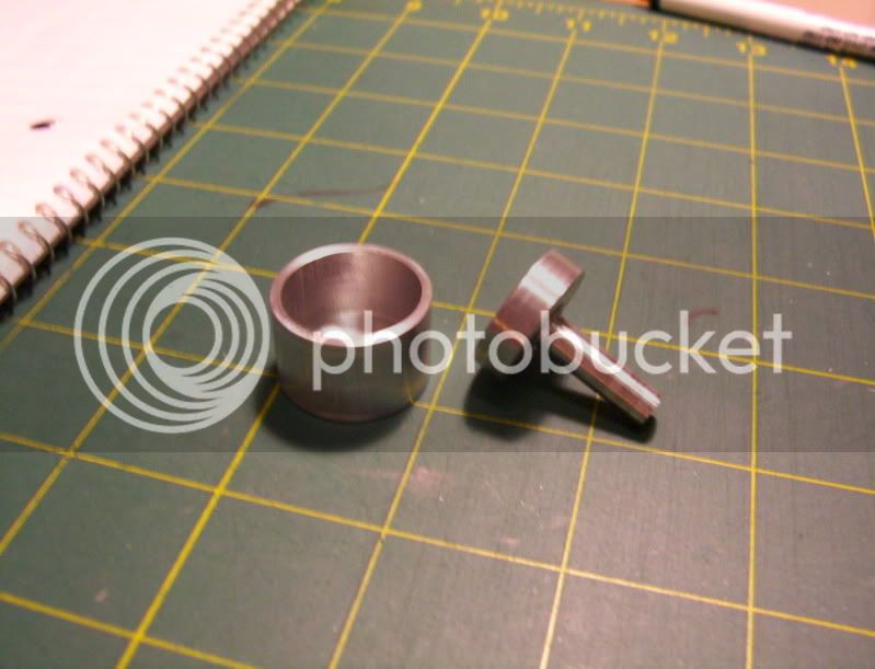
The piston and cylinder to this point.

201.jpg

202.jpg


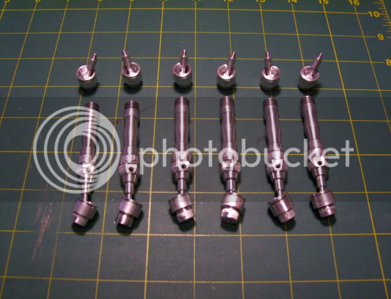
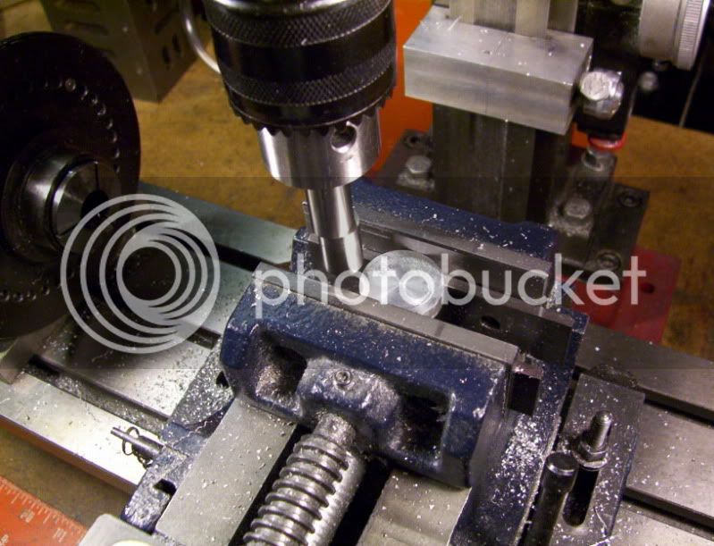
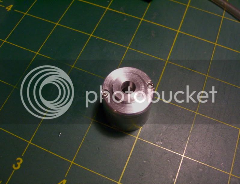
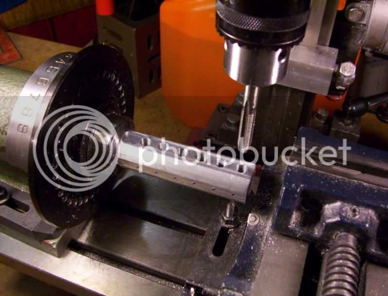
Now a hole is drilled and tapped 1/8" up from the bottom of the cylinder to a thread of 6-32.
To mount a hose connector too.

203.jpg


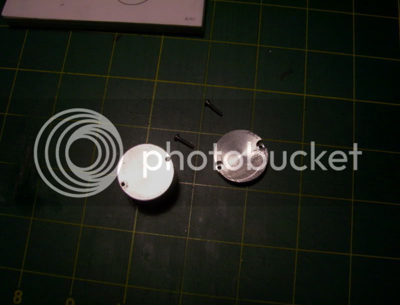
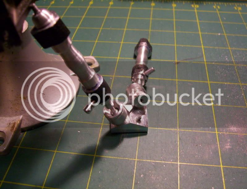
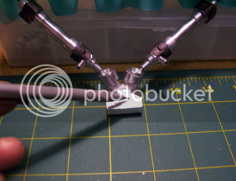
The endcaps and both hose connectors are dry fitted onto there cylinders, so some oil leakage will occure, but this is a test run to see if the calculated value of a piston movement of around 0.170" with the master cylinder will cause the piston in the driven cylinder to travel around 1-3/4".

Here it is being tested, the small driving cylinder moves it's piston less than 1/4", while the driven piston moves over 1-1/2".

<object width="480" height="385"><param name="movie" value="http://www.youtube.com/v/L-PxhT-05IM?fs=1&amp;hl=en_US&amp;rel=0

Have fun in the shop...
 

Well done Hobby! That's pretty cool. Thanks for all the explanations.
 
Nicely Done Hobs. I like your method of tapering the end of the piston rod to get a good tight fit. Everything is looking awesome.

Kel

P.S.Your "Mess" in the shop, is what mine looks like after a serious cleaning ;D

 
Thanks

KustomKB and KEL,
I appreciate the complements.

--------------------------------------------

In the last post I ended with showing the building a prototype of the actuator cylinder.

Afterward I began building all six actuator cylinders, with endcaps, and pistons to fit.
I'm still in the process of fitting each piston, I have only 2 done so far.

Here is a brief showing of the endcaps being fitted and machined to there cylinders.

First I located the holes that will be drilled and tapped into the cylinder rims, and the clearance holes through the endcap.

204.jpg


205.jpg


Then I machined the inner bore in the cylinder first.

206.jpg


Then I screwed on its endcap securely, in preparation for the hole to be drilled and reamed, through it.

207.jpg


208.jpg


209.jpg


210.jpg


Then I machined a neck into the endcap, by machining the material around it down to the top of the screw heads.

211.jpg


212.jpg


now all the cylinders, endcaps and the piston rods as well as the pistons were machined and assembled.

213.jpg


214.jpg


Now I am in the process of machining each piston to final diameter for there respective cylinders.
For a proper fit.
So far I have 2 completed at this stage, I don't want to rush this and make mistakes at this point, so I'll wait until another day to finish the rest of the pistons,

These cylinder assemblies as shown above, are the actuators, that will drive the pistons that will run the load. (in this case the simulator cabin).

These actuators, will be assembled into an arangement, to be used as a joystick input device.

Here I have begun to draw out a diagram for this joystick assembly.

215.jpg


Here are the actuator cylinders set on the diagram to give clarification of this arrangement. (to test how it will all fit together).

216.jpg


As I was playing around with the actuator piston and a model cylinder, I used a 3 ft, long tubing to see if the actuator worked as well as it did with a piece of 3 in. length.

The actuator and model piston, worked perfectly, just as if it were a short tubing, so that made me begin to think, that to get flexibility between the joystick and the model cylinders, the tubing needs to be kind of long in length, BUT that would mean a lot of hydraulic fluids, to fill the lines, so this model may be changed over to a full pneumatic system, if it can carry the load properly, OR a full hydraulic system, OR a semi hydraulic system, where I use just enough fluid to fill the model cylinders, and use the air pressure of the actuators to push this oil back and forth in and out of these model cylinders.

So these three options are left open to me at this time, once I get the joystick system done, then I'll be able to experiment to see which system would work best under this kind of load.

Well that's all for now.

Have fun in the shop...

 
This weekend was more or less designing and fabricating a 'pneumatic / hydraulic', joystick module.

Here is a template drawn out on my cad program, that I will use to fabricate the base of the joystick, the actuator cylinders can be seen at the top, these are spring loaded with spring retaining buttons screwed on top the piston shaft.

217.jpg


Then today I started working on a 'air / fluid' distributing manifold, that will be situated at the front of the joystick, where the actuator cylinders will tie into, then from the manifold, each tubing will tie into the model cylinders, the manifold will be comprised of a oil filling reservoir, should I need to resort to making this work by hydraulic pressure.

I started with a piece of 1" dia. alu. round bar.
tramed it in on the dividing head, and began to machine flats on 3 sides.
First the top side with a 1/2" endmill so as to make an area for the oil reservoirs, holes to be drilled and tapped.
Then on the 2 adjacent sides with a 1/4" endmill to make a flat for drilling thru holes that will later be the tubing connectors.

218.jpg


219.jpg


220.jpg


Now the tubing connector thru holes are drilled.

221.jpg


And the oil reservoir holes are drilled half way through to meet the adjacent holes, and are tapped to recieve the threaded fixture, be it a cap alone, or a cup and cap, haven't decided yet.

222.jpg


And finally the bottom is machined flat.

223.jpg


Now to form the tubing connectors onto this I need to rough out the material around the thru holes making 1/4" squares, so the form tool can form the spigots.

224.jpg


225.jpg


226.jpg


227.jpg


Now the form tool is put to use, to form the spigots for the tubing connectors.

228.jpg


229.jpg


230.jpg


Now some clean up with a large endmill to make things look more tidy.

231.jpg


232.jpg


Next I need to do a little more profile work on it, then make the capping fixtures for the oil reservoirs, then from there I will be ready to start the joystick base and assemble the unit together, then give it a test run with the model cylinders, as a proof of concept.

If it works properly, then I'll be ready to continue work with the rest of the model, starting making the base for the model cylinders to attach too.

That's all for now,

Have fun in the shop..
 
Fascinating project! Can we see a better pic of the form tool in the last series of pics?
 
has been a while since I looked in on this thread. wow lots of progress fantastic documentation ,step by step and way over the top scale assembly benches and pallets. Keep it up man.
Tin
 
Tin Falcon

Thanks for looking in, and the uplifting complement..
-------------------------------------------------------

Hello,

This is the possible layout for the joystick module, maybe...
233.jpg


This is the fluid input manifold, that will couple the joystick actuators, to each model hydraulic cylinder.

234.jpg


235.jpg


Now with all that machined, it's time to turn my attention, back to the model cylinders, what I have done is drawn up the foundation layout, where each cylinder should be located at, then took some measurements, to figure out the compound angle needed to make the base units to connect the cylinders to.

Then I made a quick plywood jig, to hold the base unit workpieces, in position, for machining, in the angle tilting vise, on the mill. This will be several machining operations.

236.jpg


237.jpg


First operation completed, the base units are machined to compound angle.

238.jpg


Now I want to drill and tap for the anchor screws, which will attach the cylinders to it.

First the jig is reused but this time double stick tape is used to secure it to the vise, for locating each workpiece.

239.jpg


240.jpg


241.jpg


And now the machine work.

242.jpg


243.jpg


244.jpg


245.jpg


The anchor screws are made by cutting the heads off of a 6-32 screw.

246.jpg


247.jpg


And now the cylinders are dryfitted to check for fit.

248.jpg


Now, instead of the model cylinders having there hydraulic tubings connected directly from the joystick module, I decided on making an intermediate connection, where the model cylinders are directly connected to a hose coupling fitting attached to the base, with enough slack to allow movement of the cylinder through it's ball joint connector.

Then the main hydraulic line, connect to the other end of this hose coupling fitting, and then the hose coupling fitting will attach to the base unit, probably right here.

249.jpg


That way there the main line can be securely attached to a stable base so not exposed to constant movement, from the model cylinder, also removing the joystick module will be much easier, because it will not interfere with pulling hoses off of the model cylinders, but rather the base units.

So here is the starting of building these hose coupling fittings.
Pencil drawing on the board maybe a little hard to see, but here is a description, of how it is being made, to date.

250.jpg


The fitting is hard to see in the drawing, but it is going to be made as one piece, the two input tube connectors, (that will attach to tubing from the joystick), will go on one side of this, while 90* from each side of these will be machined another tube connector, which will connect to the model cylinders themselves.
And this whole unit will attach to the base unit for each set of model cylinders.

The dimensions of the workpiece needed for this will have to come from a round stock 1.250" dia. aluminum. The finish length after first lathe machining, will be around 1.500"
A 3/8" dia. spigot will be turned down on this for a rough length of 1/2", and drilled and tapped for a 6-32 thread. This spigot will serve as a standoff above the base unit it will attach to, later 1/4" will be taken off the length of the standoff, befor final assembly.

251.jpg


252.jpg


Machined to fit inside a 3/8" 5C collet, for machining purposes on the mill.

253.jpg


drilled and tapped 6-32 thread for attachment to its base unit.

254.jpg


Now placed in spin jig, for the locating and drilling of the model cylinder hose coupling, holes which will be spaced 180* from eachother, these will be machined 90* from the side of the workpiece. (on the flat).

255.jpg


Now once this is drilled, and all milling around the hole is done to make a square stud, I'll then transfer the workpiece to my benchtop drill press to do the actual machining with the form tool on the piece, held in a vise, the reason for this is because my drillpress has a stronger motor than my micro mill drill machine, and this alleviates hard wear and tear off of my milling machine for this kind of machining.

Once the spigots are formed, then I will need to put the workpiece in my angle tilting vise, and tilt it to 60*, to match the angle of the base unit it attaches to, this is so the spigot will be horizontal when this coupling is attached to its base, if not then the spigot would be pointing down too far.
Again all machining to make a square stud will be done, on the mill and probably a jig will be made to hold the workpiece at the angle in a vise on the drillpress, for final spigot forming.

Well that's all for now, slow progress, at times but it's all in the fun of learning new techniques, and challenges of making precision parts.

Have fun in the shop....


Hobby, you do incredible work on what appears to be a 7x lathe and small mill.

Keep up the good work. I don't always comment but I am faithfully following along.

This is one of my must read threads.


Ron


Latest posts

Back
Top