- Joined
- Dec 5, 2009
- Messages
- 510
- Reaction score
- 47
Hello everyone,
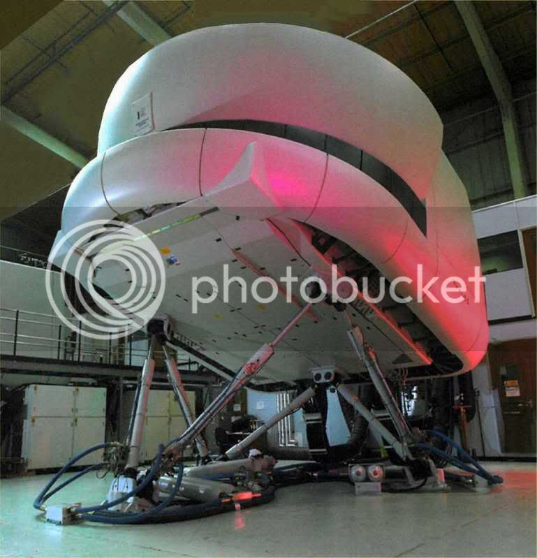
This is a picture I found off the innernet, of a full size flight simulator,
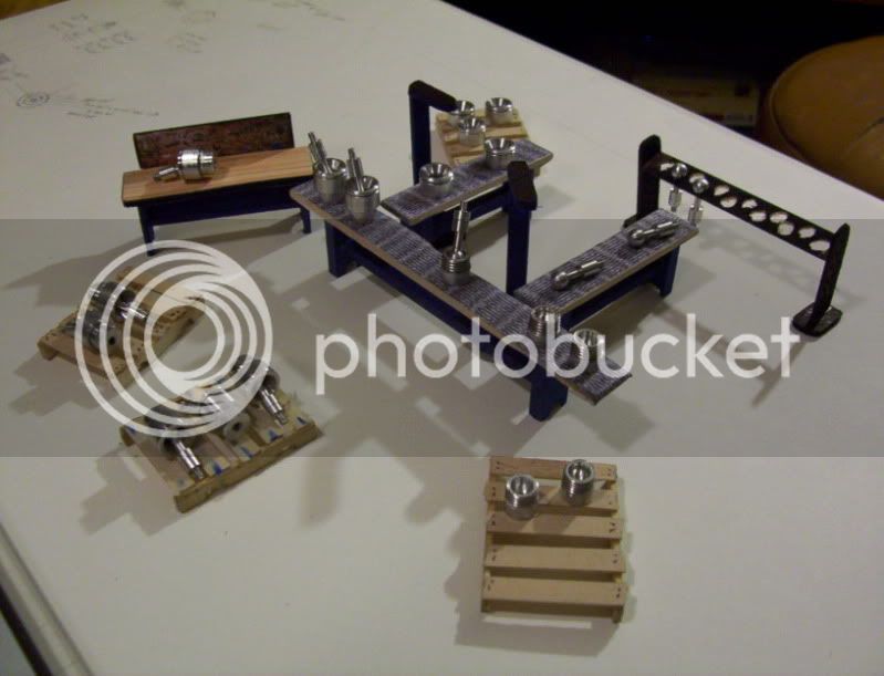
I would like to try to make a very small miniature working mechanical model of it.
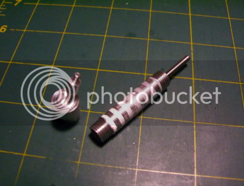
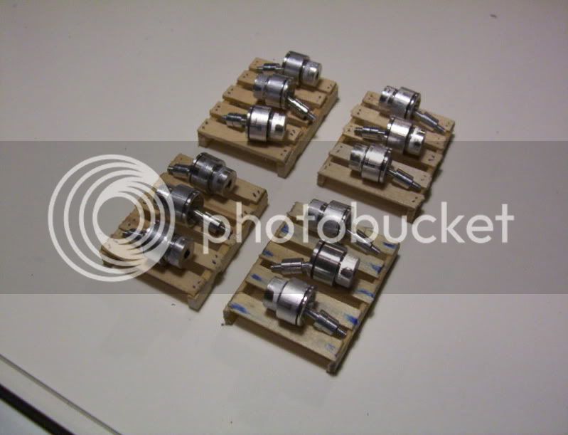
I'm approaching this with a different concept for the hydraulic cylinders, this time I'm building double acting cylinders, using only one hose connector, which will take care of both the push and pull of the piston. Also I' am machining the threads on the outside of the cylinder to hold the top and bottom endcaps, this makes it much more easier to fit the piston to the cylinder, as well as allows the total length of the cylinder to be made smaller with the same amount of piston movement, as when the threads were internal, as before.
I found a real nice way to make miniature pistons, by using loctite thread locker to hold the piston to the rod, and the use of my lathe as a horizontal press.
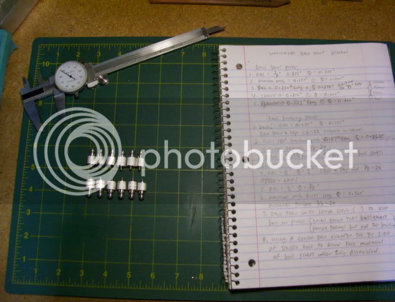
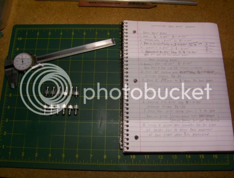
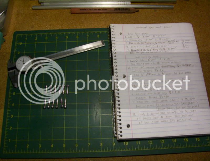
Here are the steps in making miniature piston and rod assemblies.
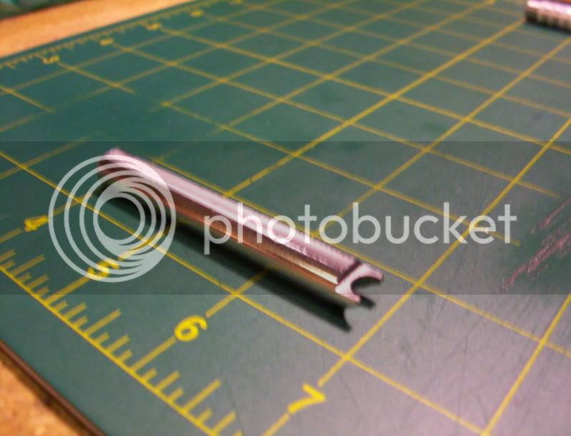
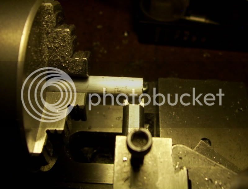
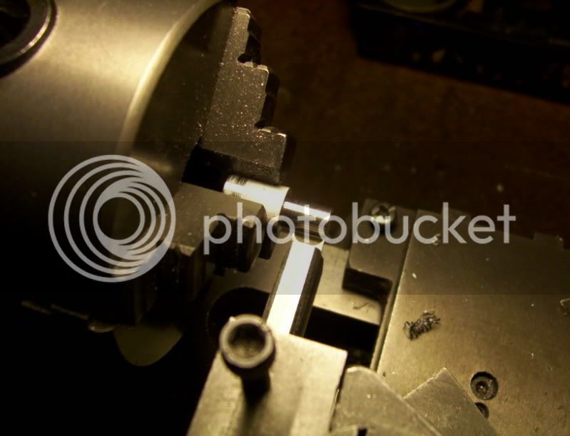
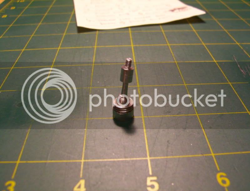
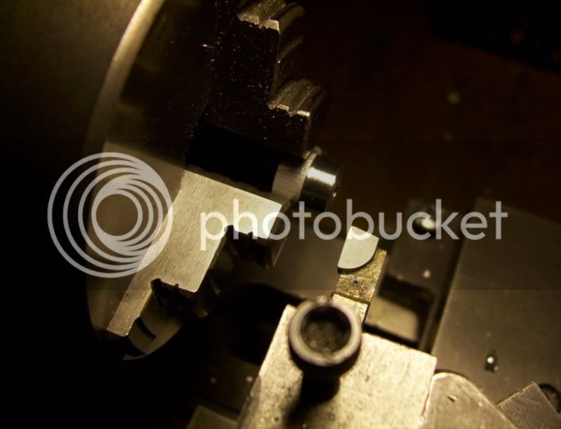
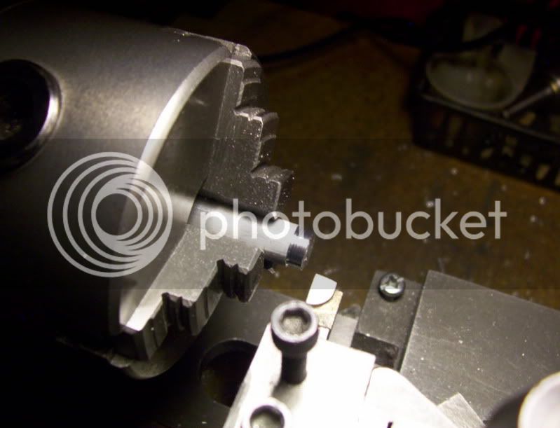
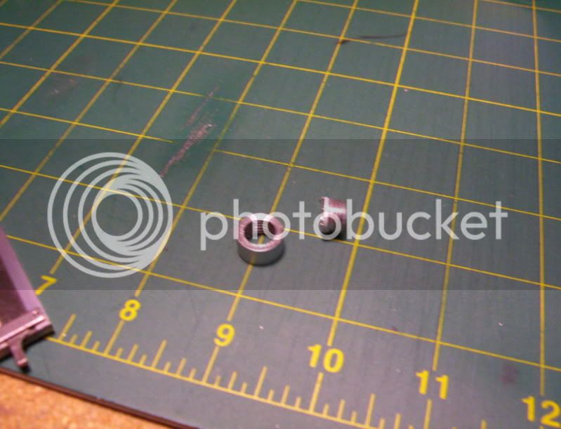
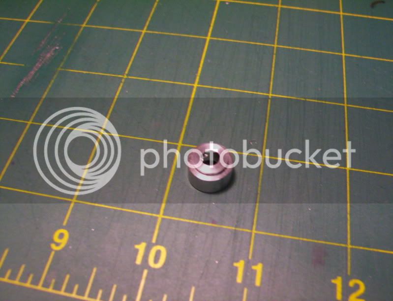
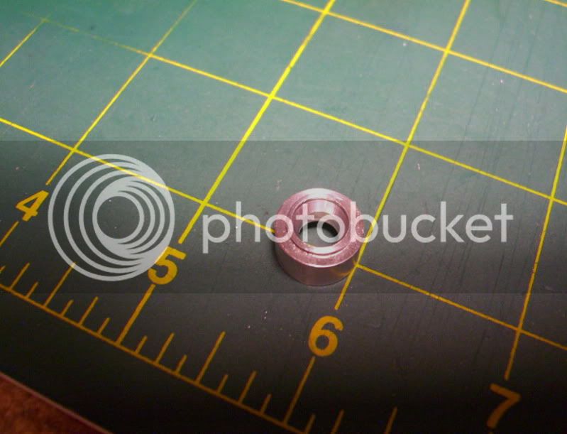
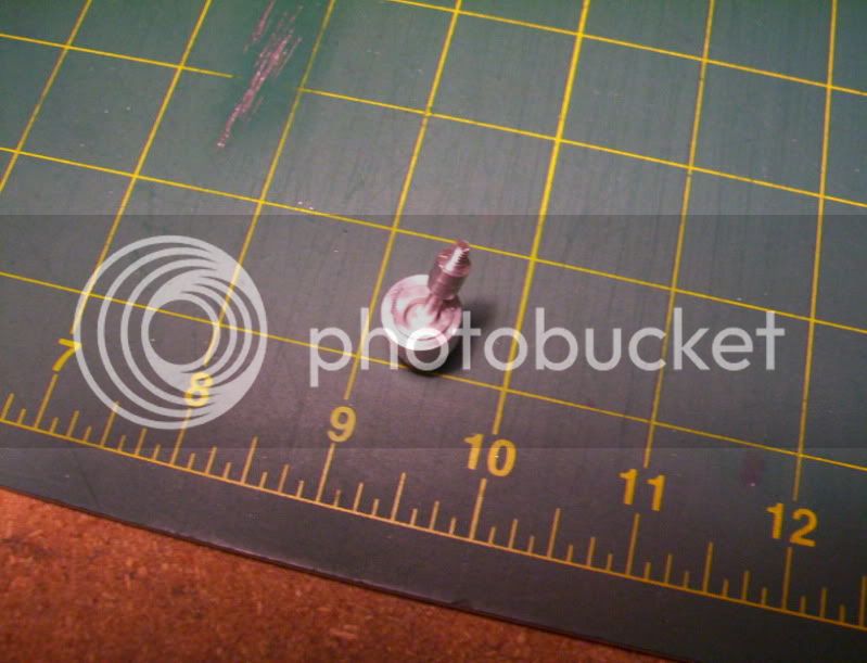
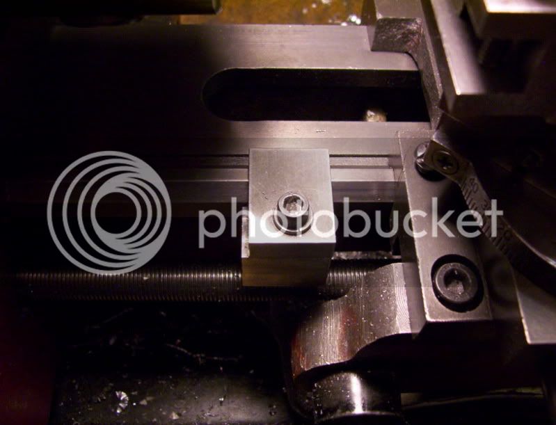
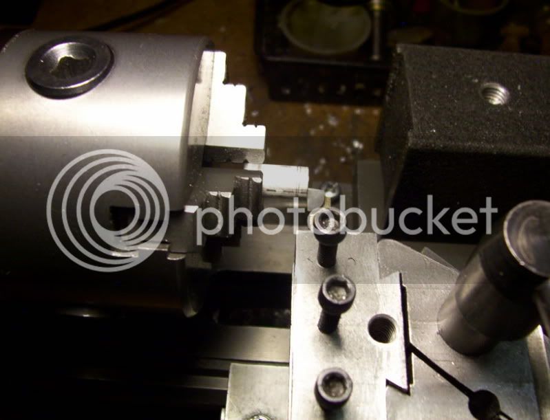
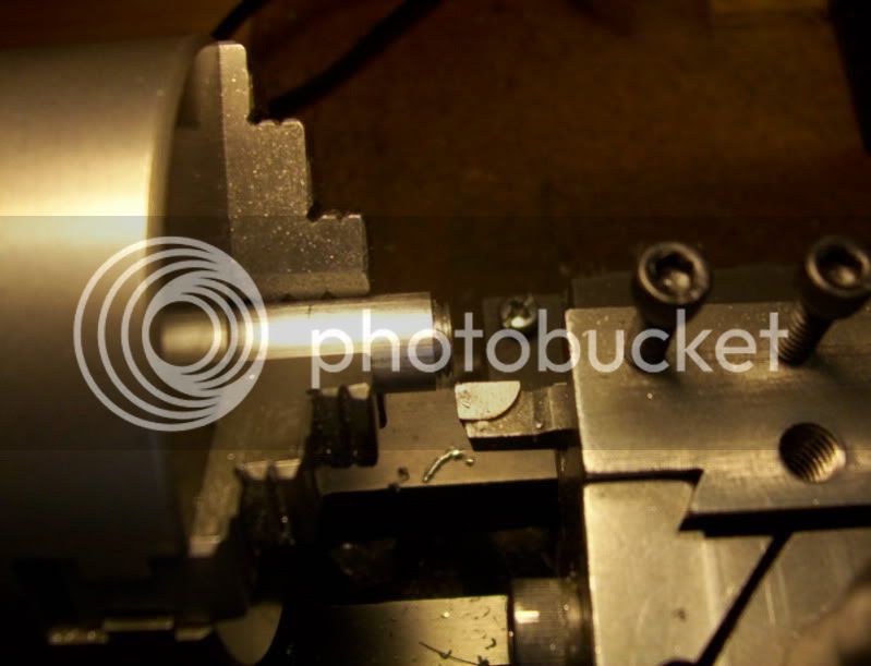
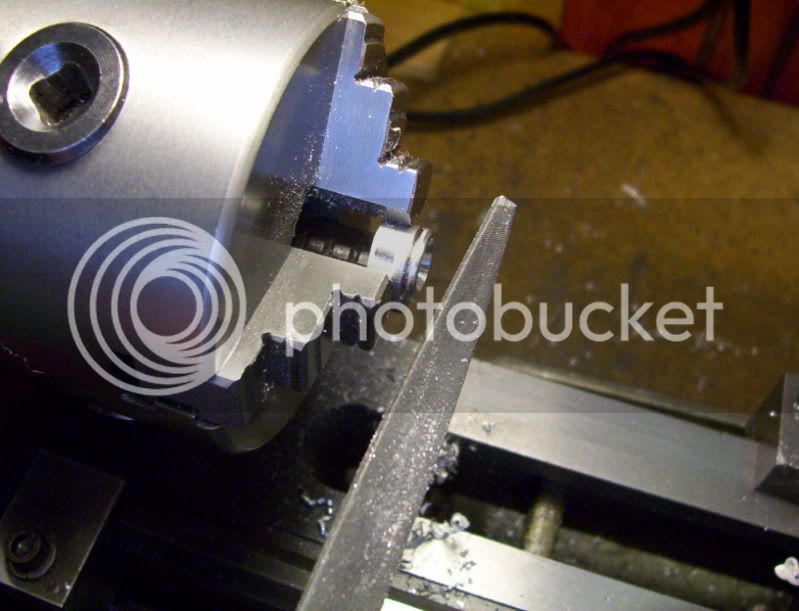
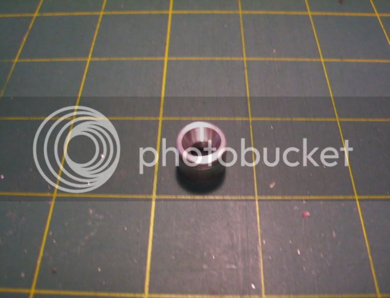
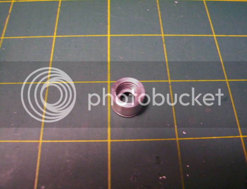
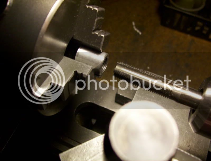
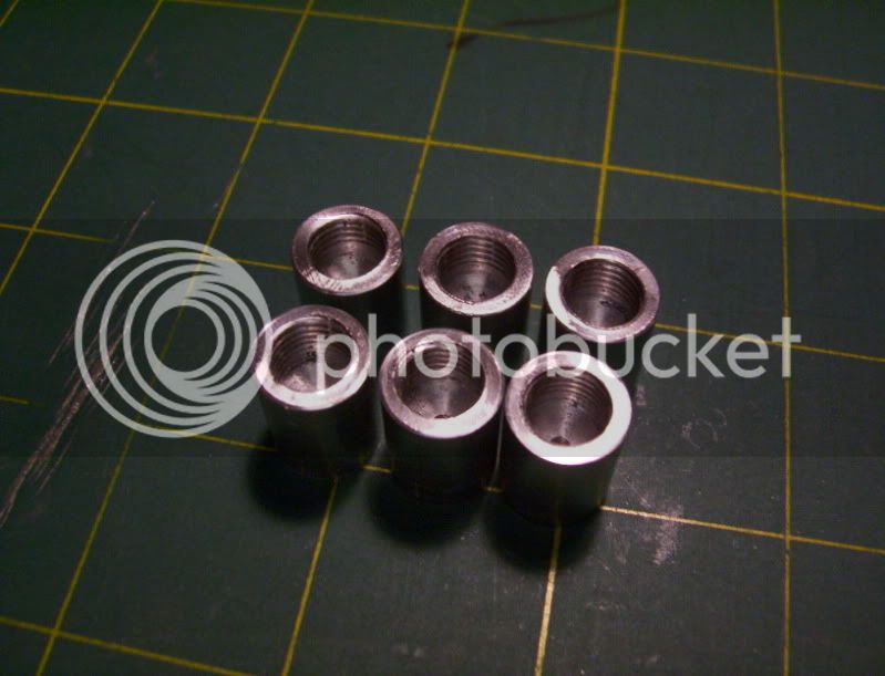
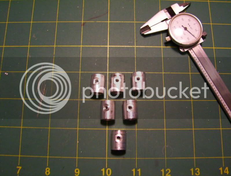
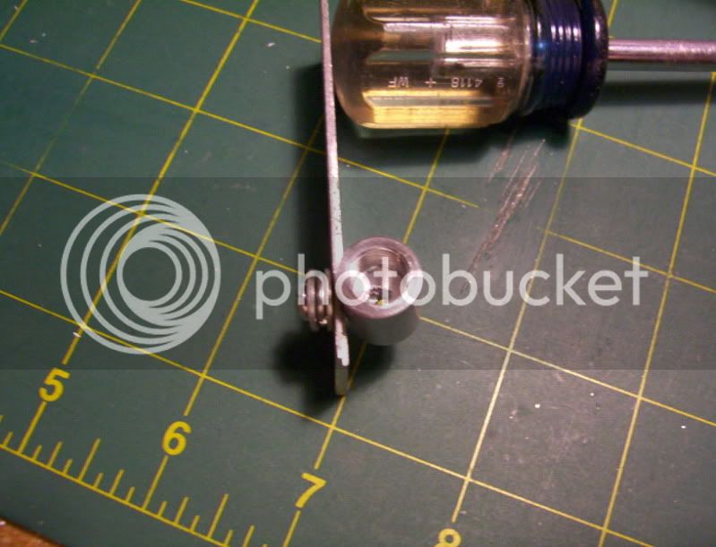
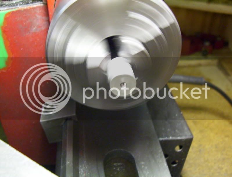
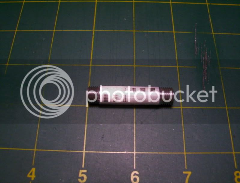
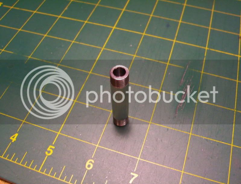
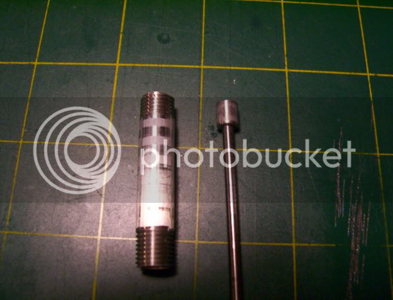
First I machine the cylinder with external threads and internal bore.
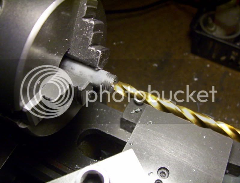
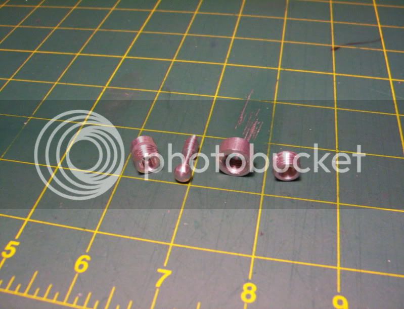
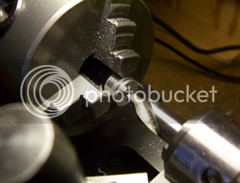
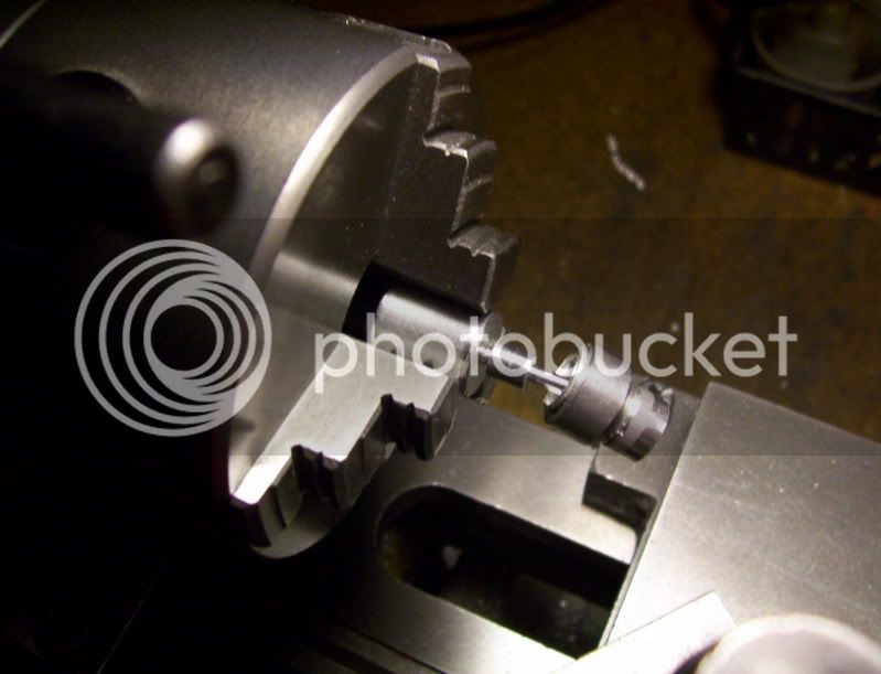
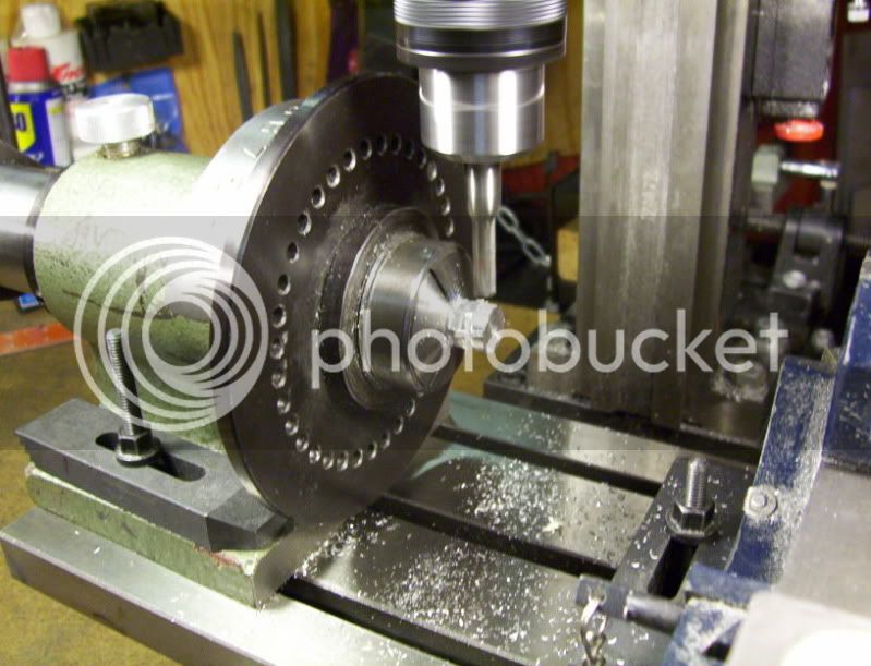
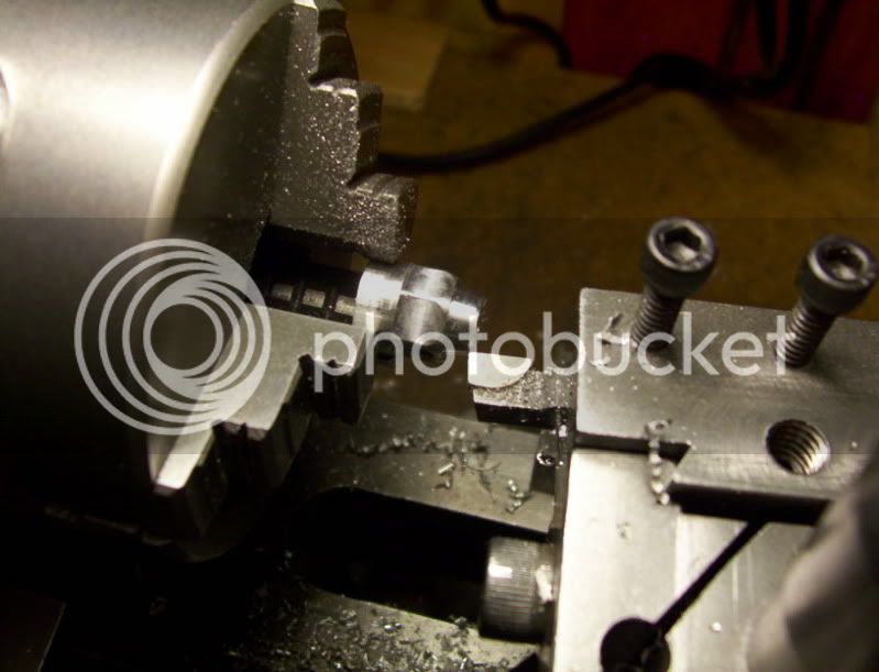
Then I face the piston stock, and begin with centerdrilling the proper size hole, for the piston rod.
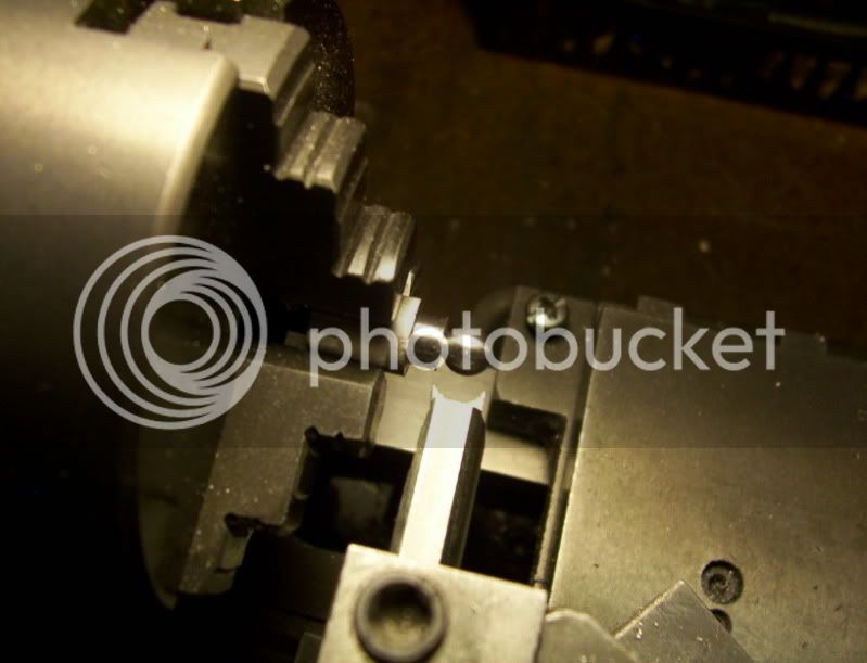
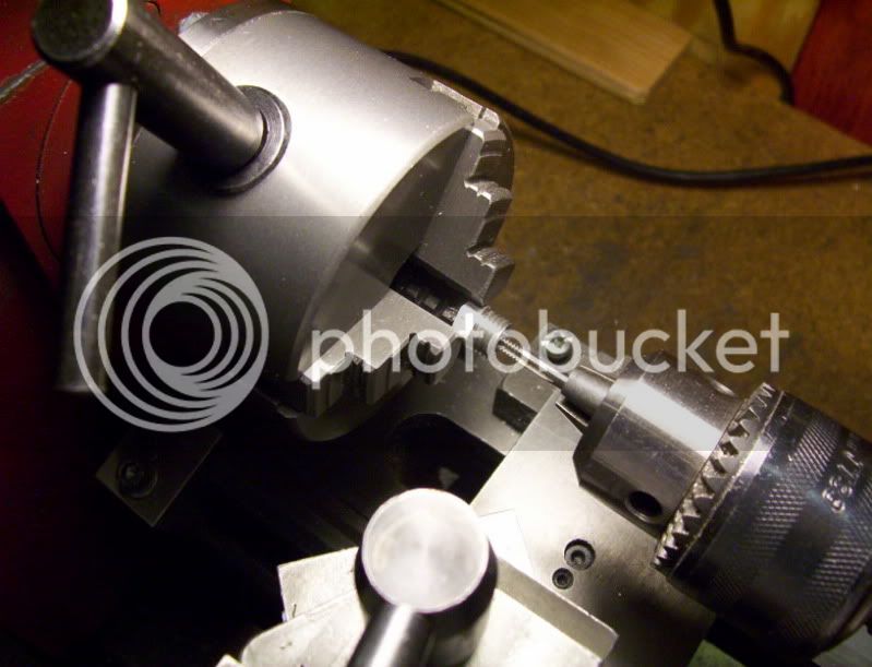
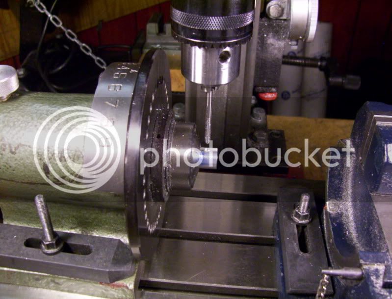
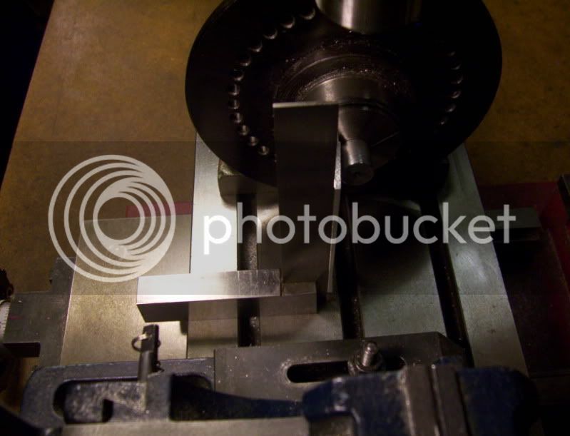
Afterward I set up for the drilling of the rod,
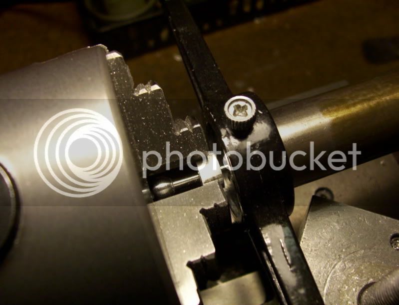
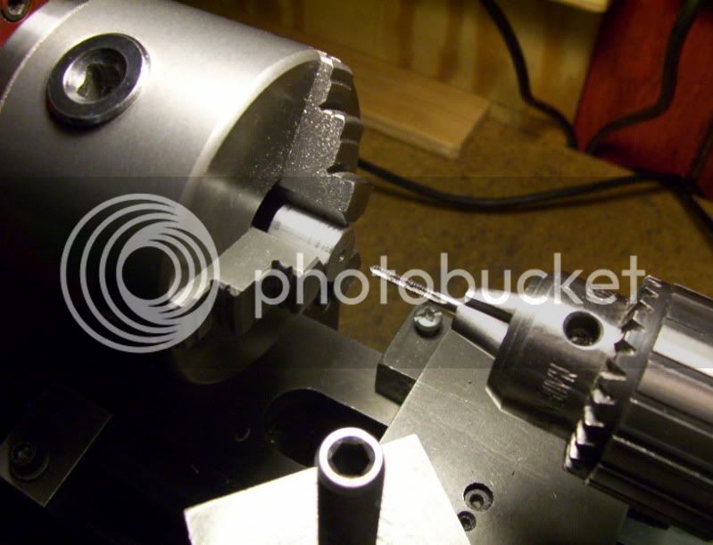
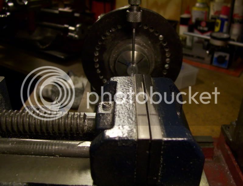
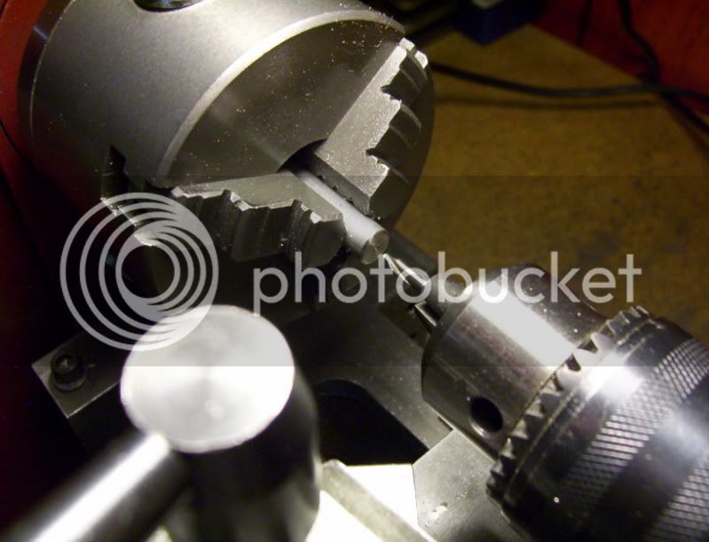
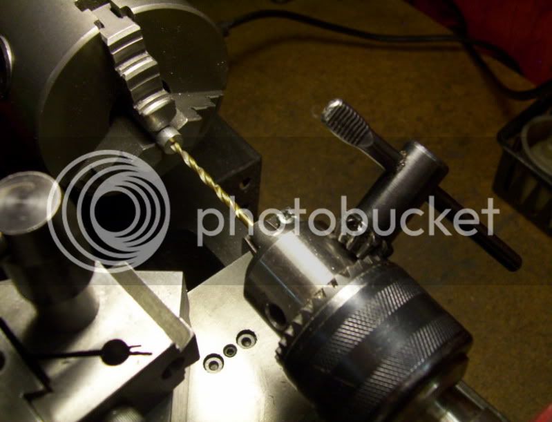
First, when ever you tighten a chuck key in a drill chuck, sometimes the drill will not line properly up straight out, and the bit goes on a slight angle bending its way into the preveiously drilled starter hole,
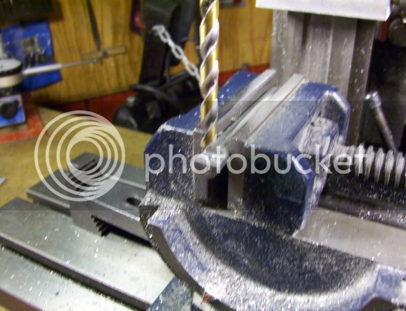
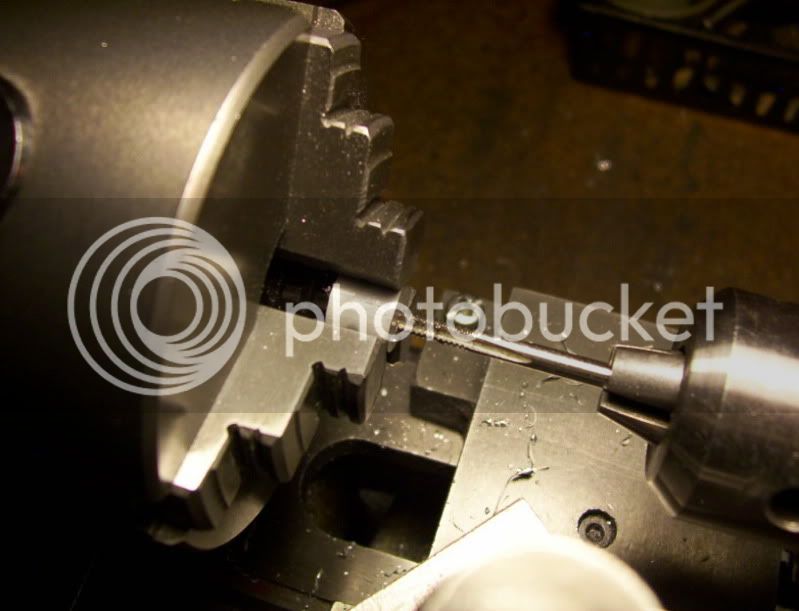
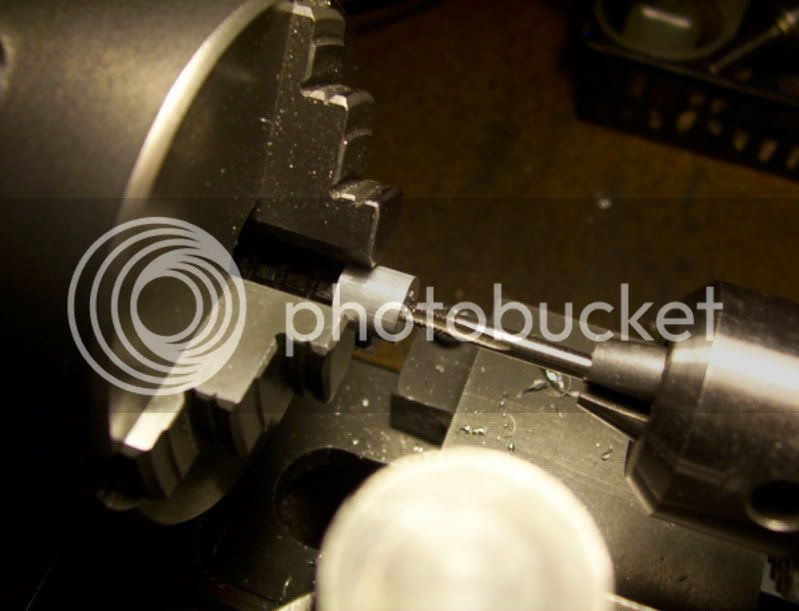
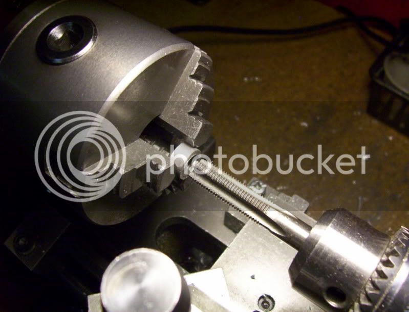
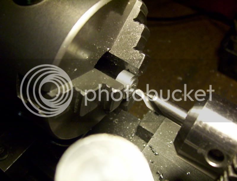
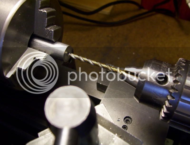
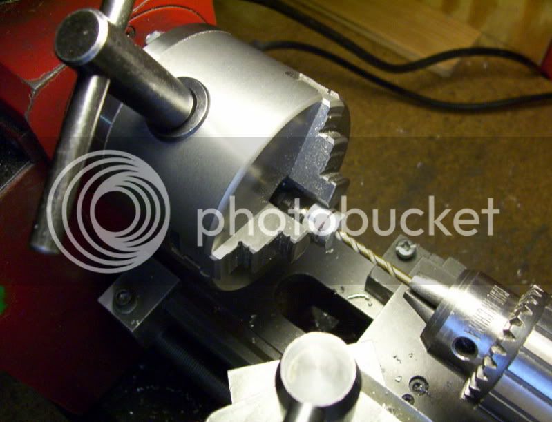
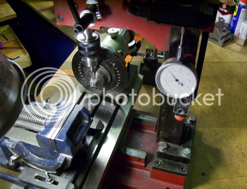
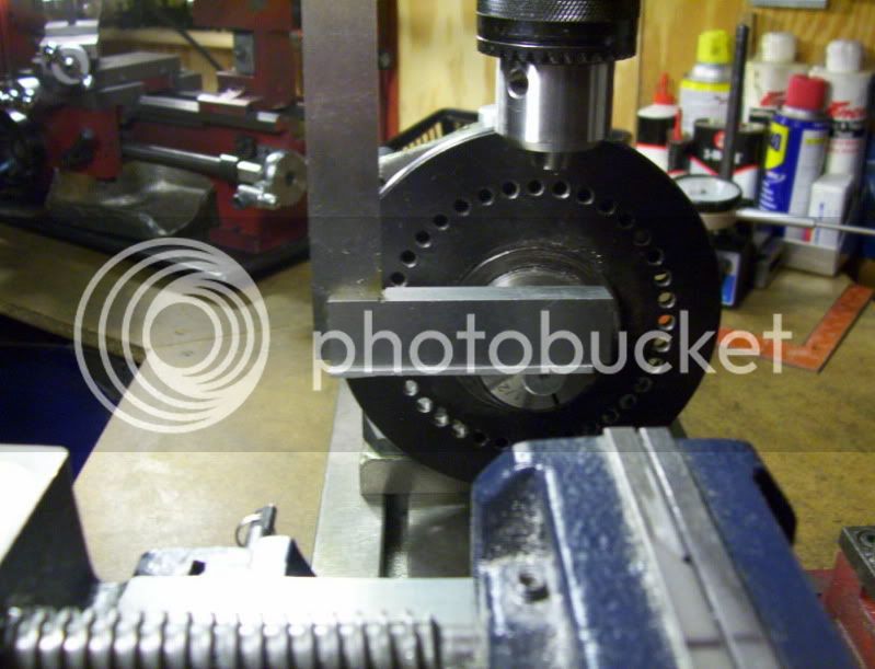
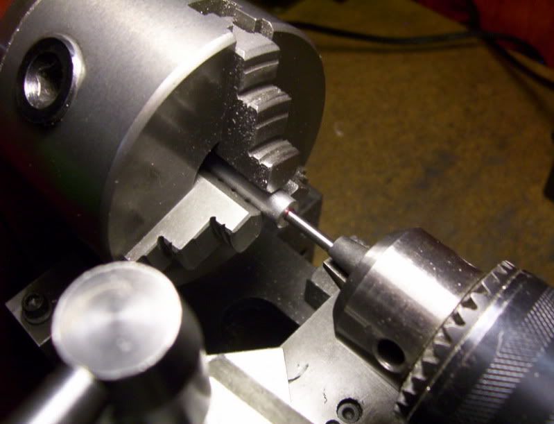
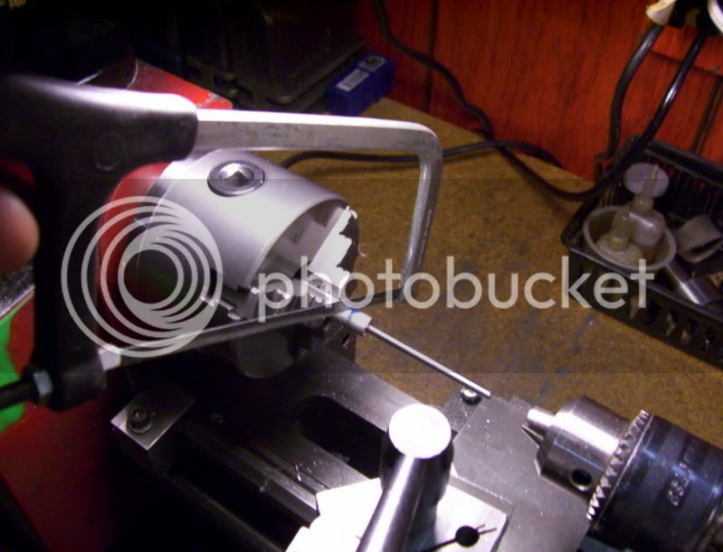
I stumbled on a way to make sure the drill bit and reamers ends up on target everytime, by loosly placing the drill bit in the chuck, locking down the tailstock then holding the bit in the starter hole, begin to tighten the chuck, tighten as tightr as possible, and now the drill or reamer is set to exact target of the starter hole.
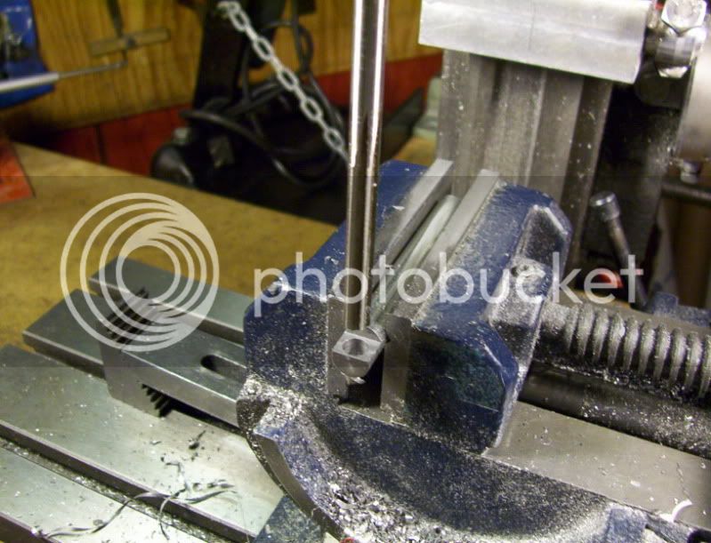
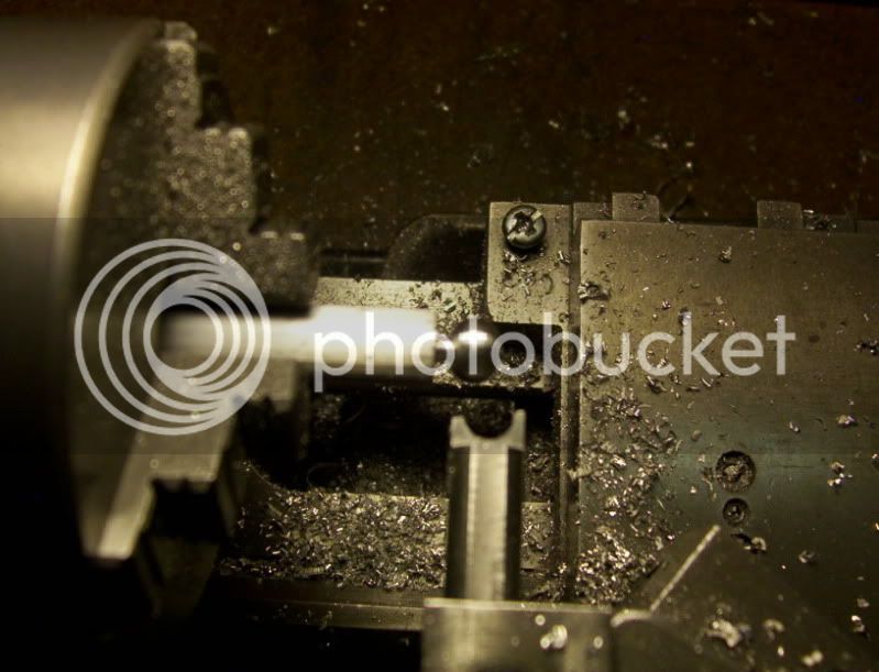
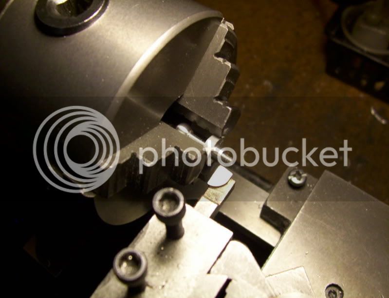
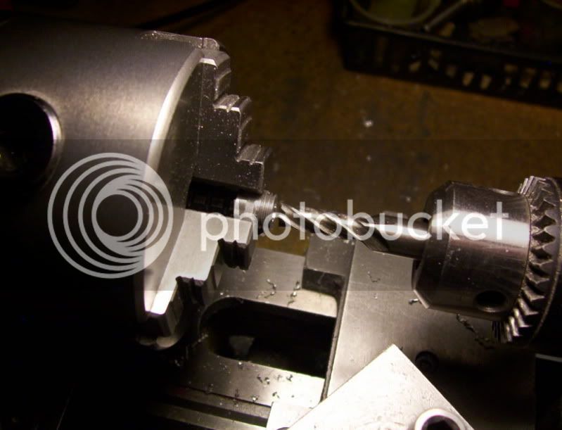
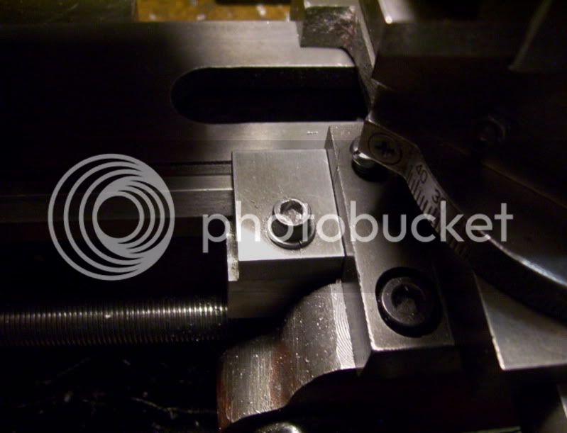
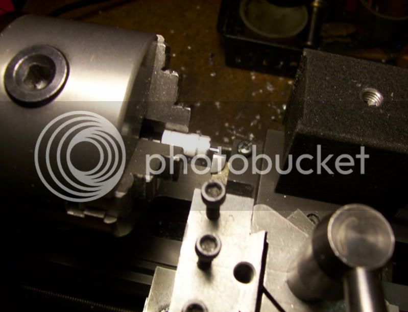
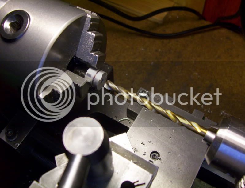
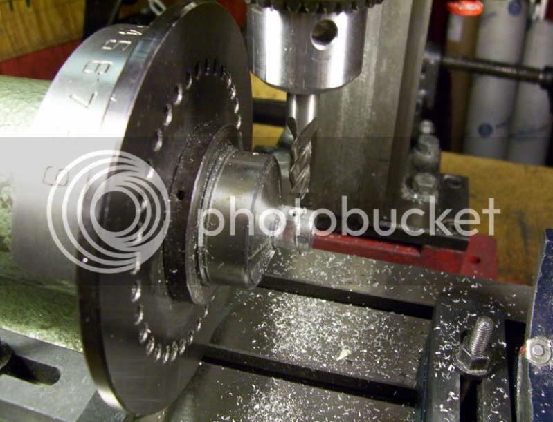
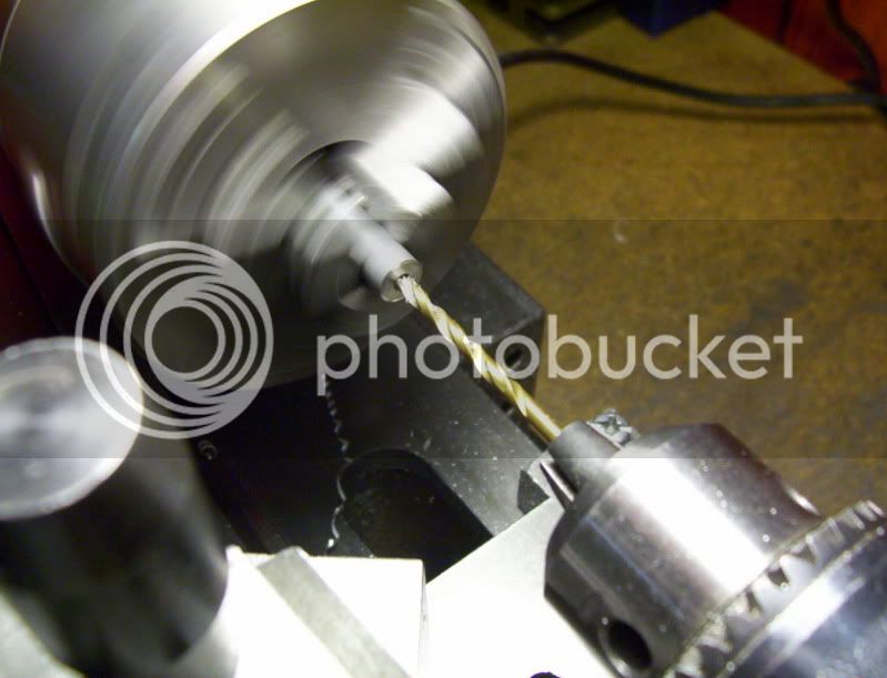
Now I drill the hole to required depth for reamer to follow.
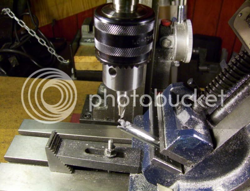
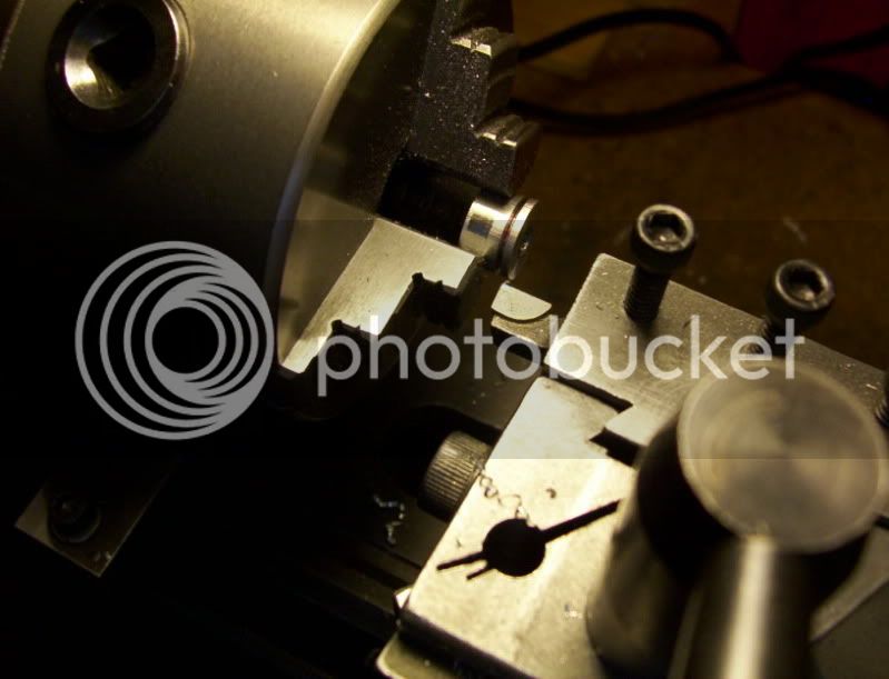
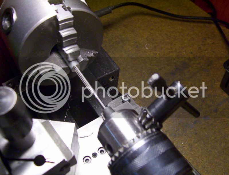
Then again with the reamer, I set it in the hole left by the drill and proceed to tighten the chuck.
Now back to the piston build.
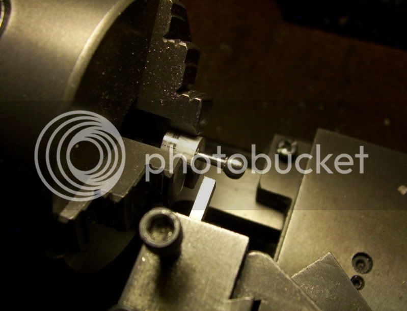
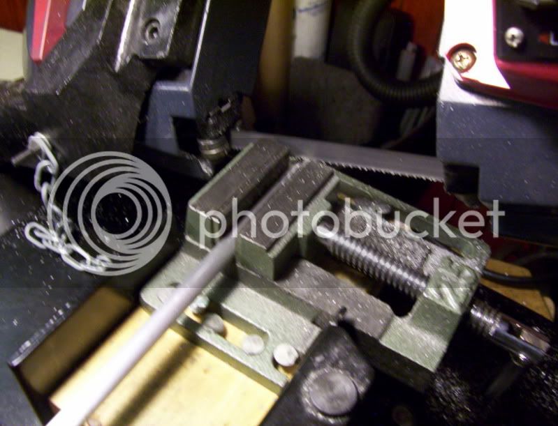
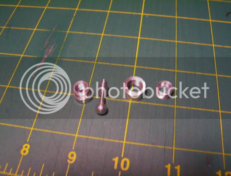
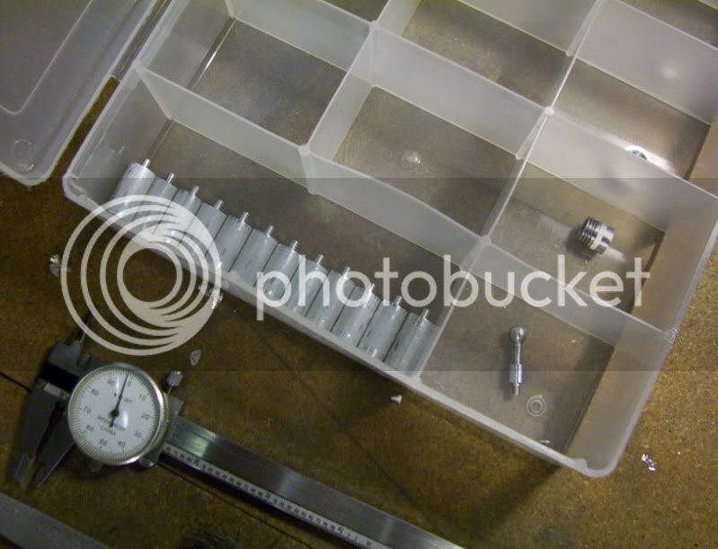
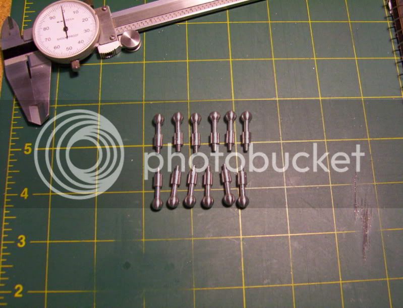
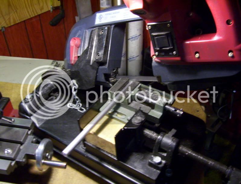
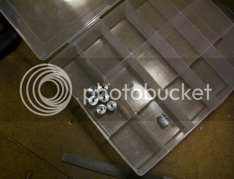
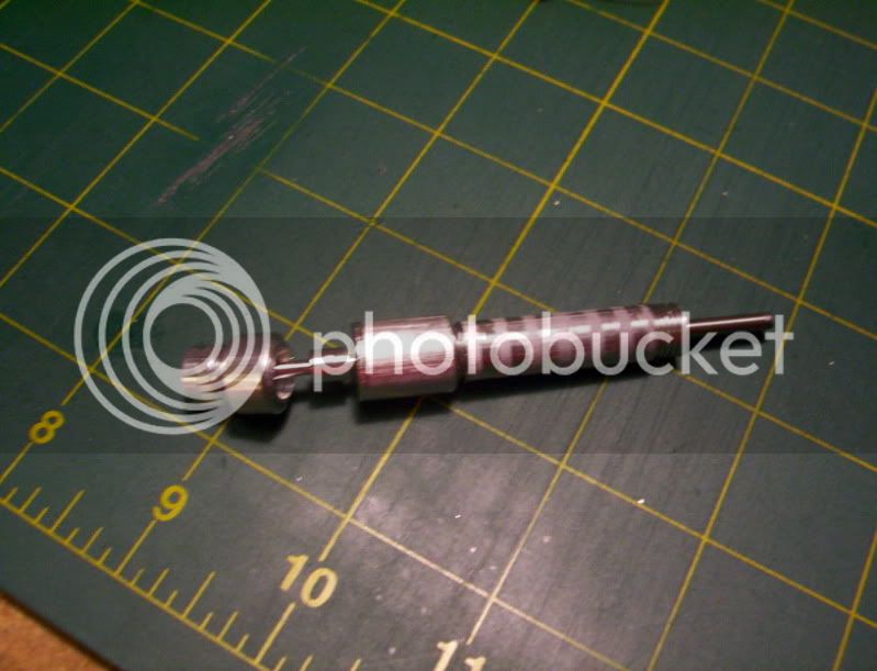
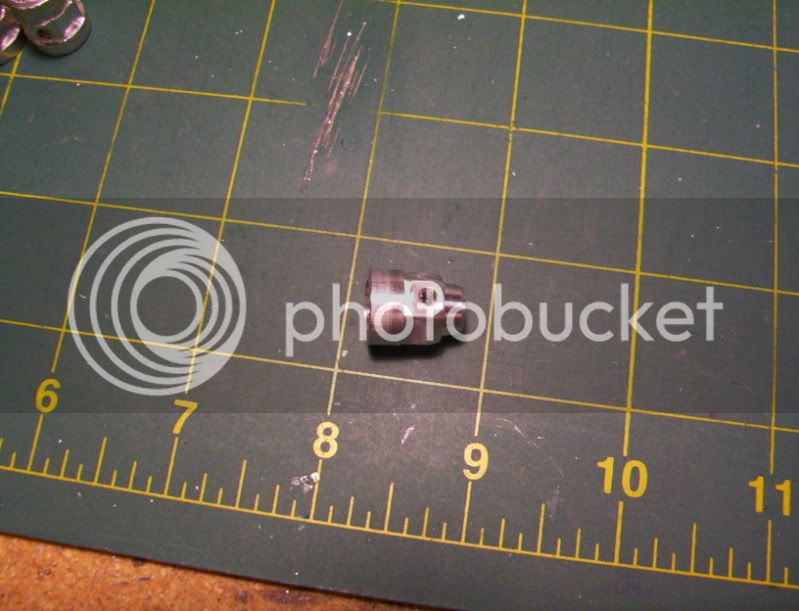
So Now the piston blank is drilled and reamed ready for it's rod, I then cut the rod blank, to appropriate length.
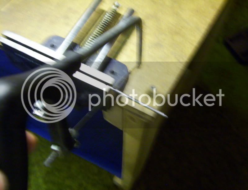
Then I file off the extreme large burr left by the sawing, to a taper that will allow the rod to slide into the hole in the piston, easily.
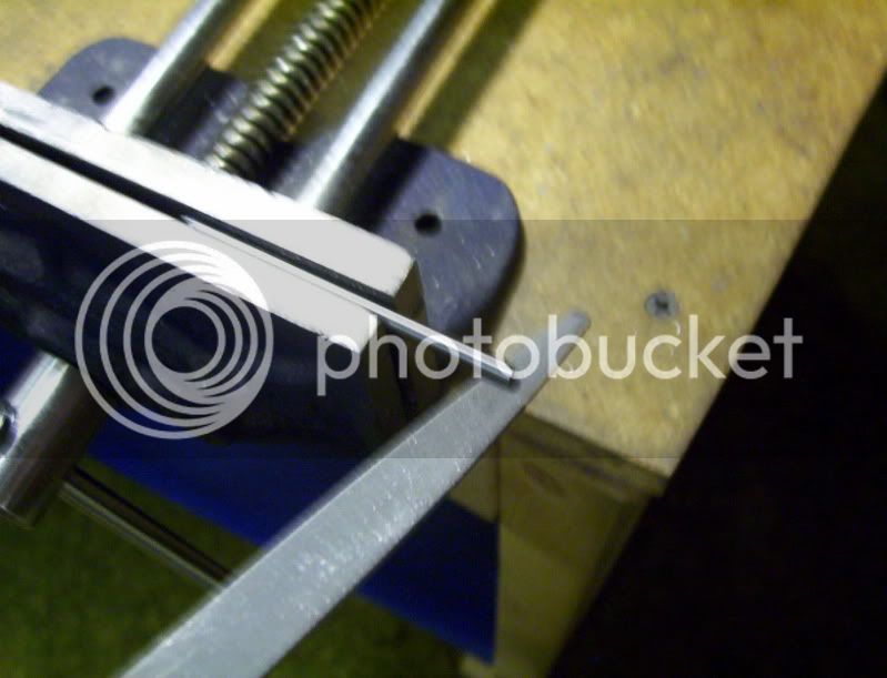
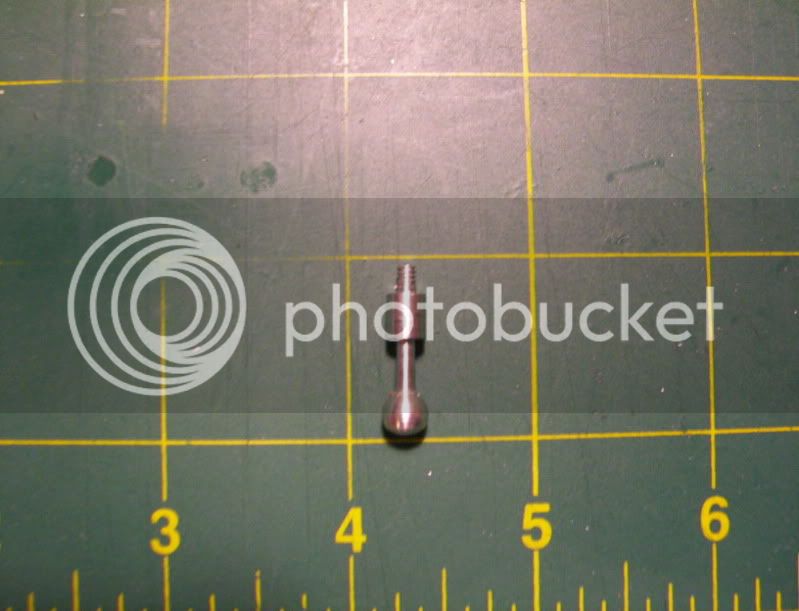
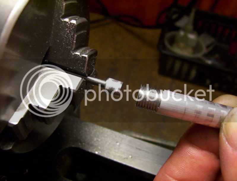
Then I take it back out and file the one end of the rod on top to give a slight burr hanging around its diameter.
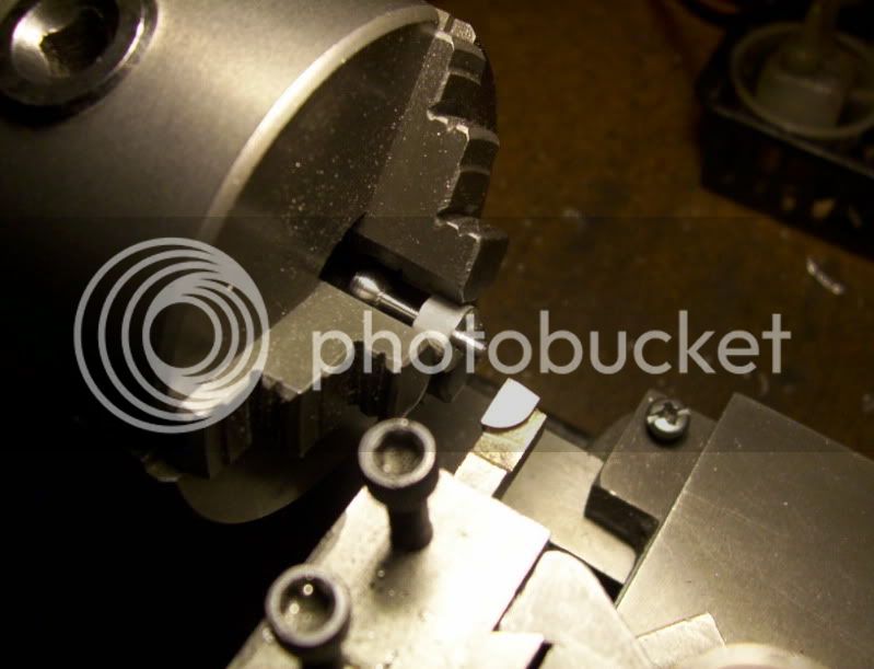
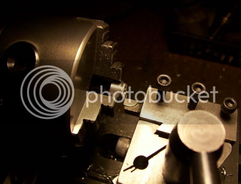
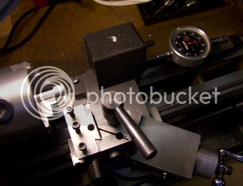
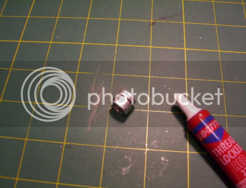
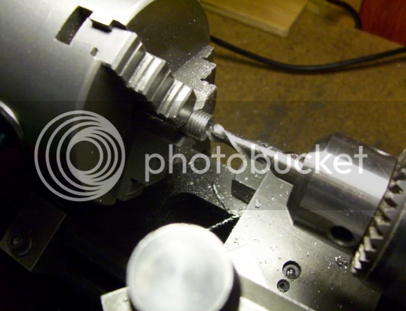
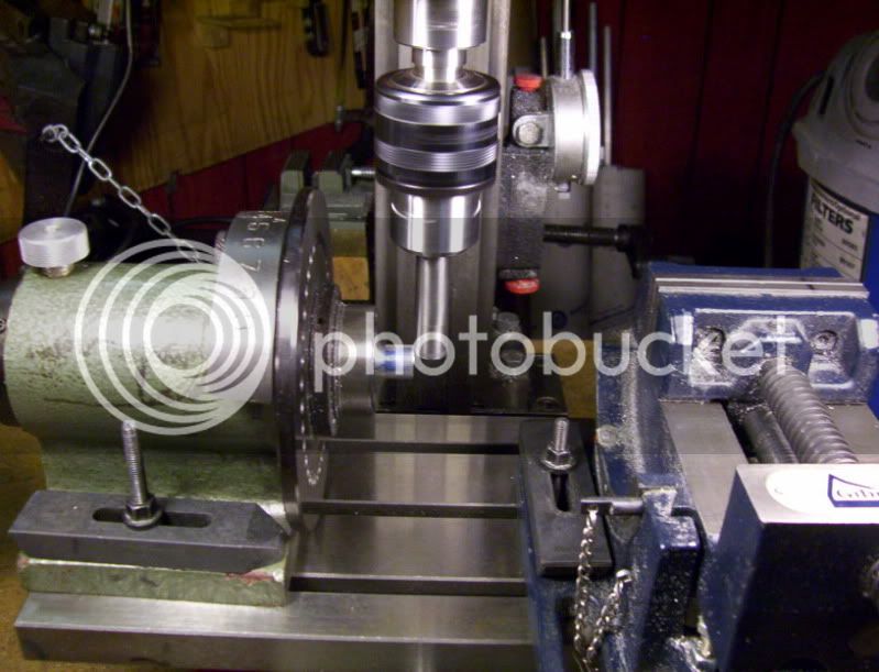
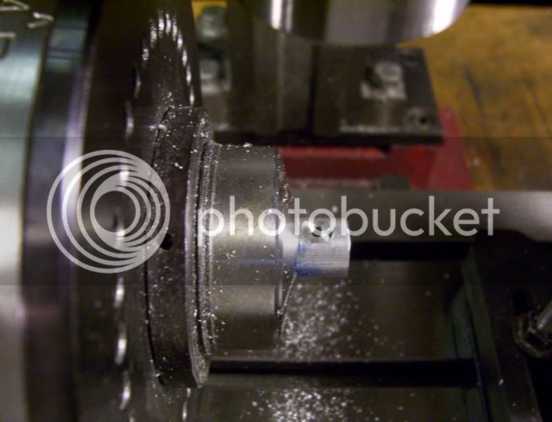
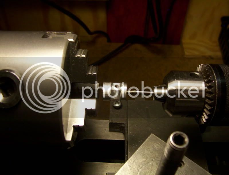
Now I place the prepared rod in the tailstock drill chuck with the end with the burr sticking out and tighten it and then add loctite glue to the tip of it.
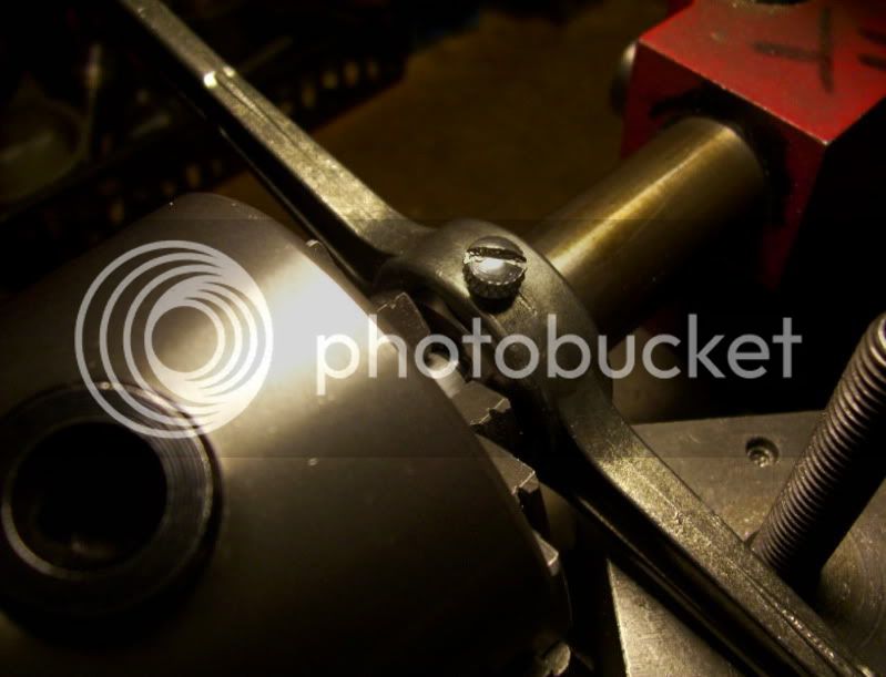
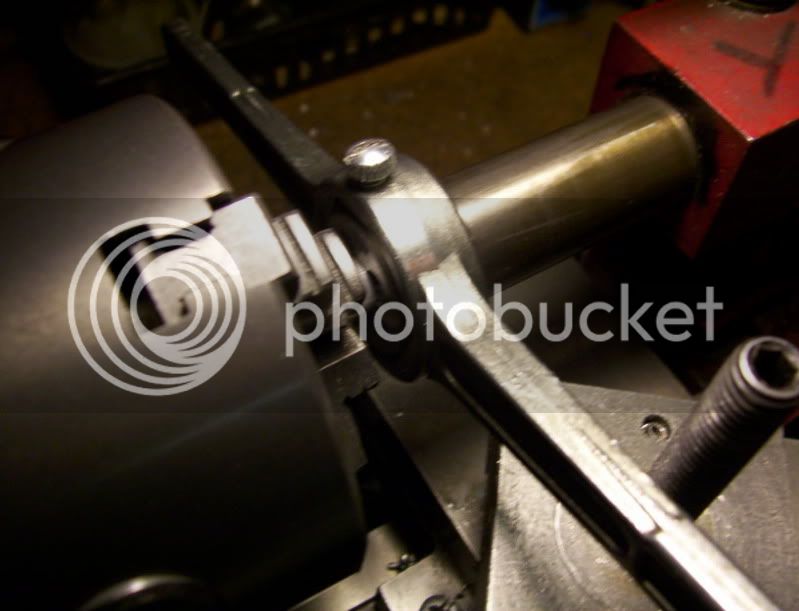
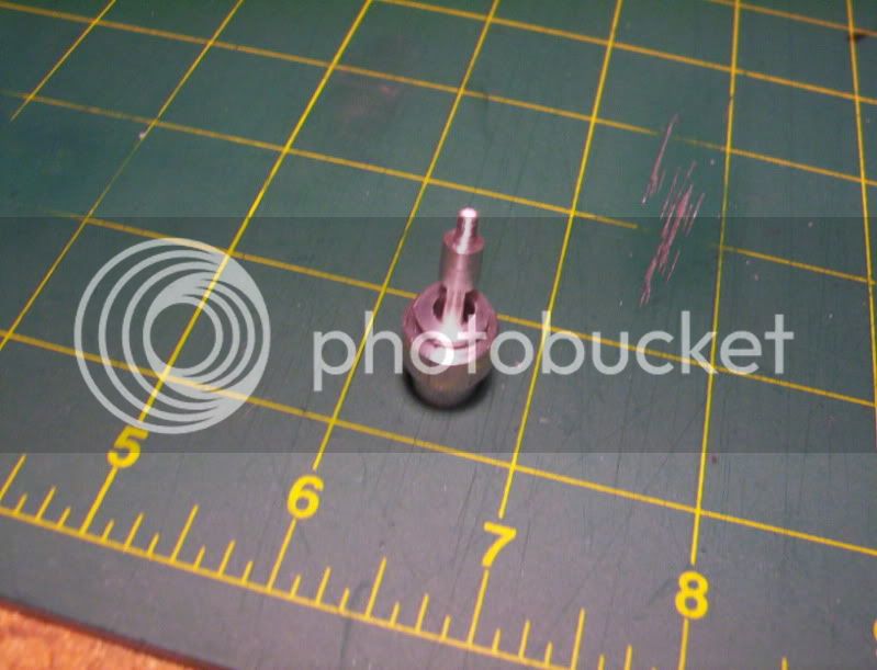
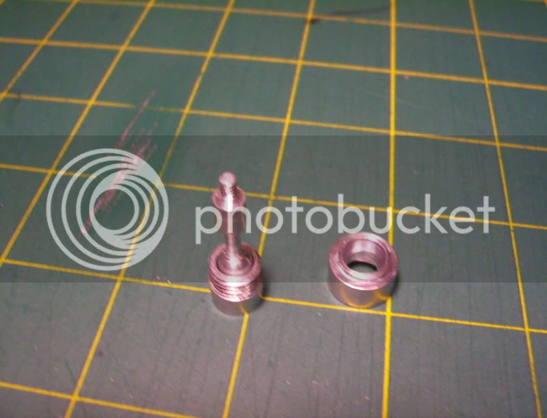
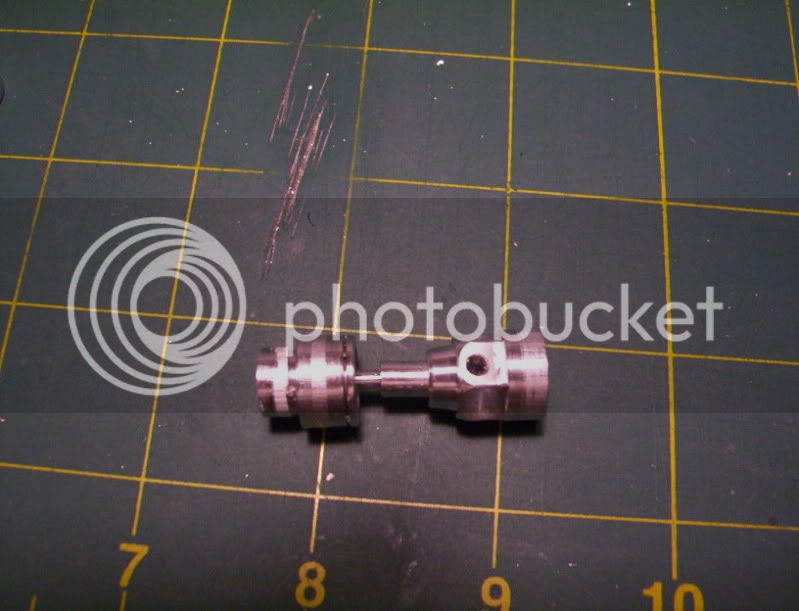
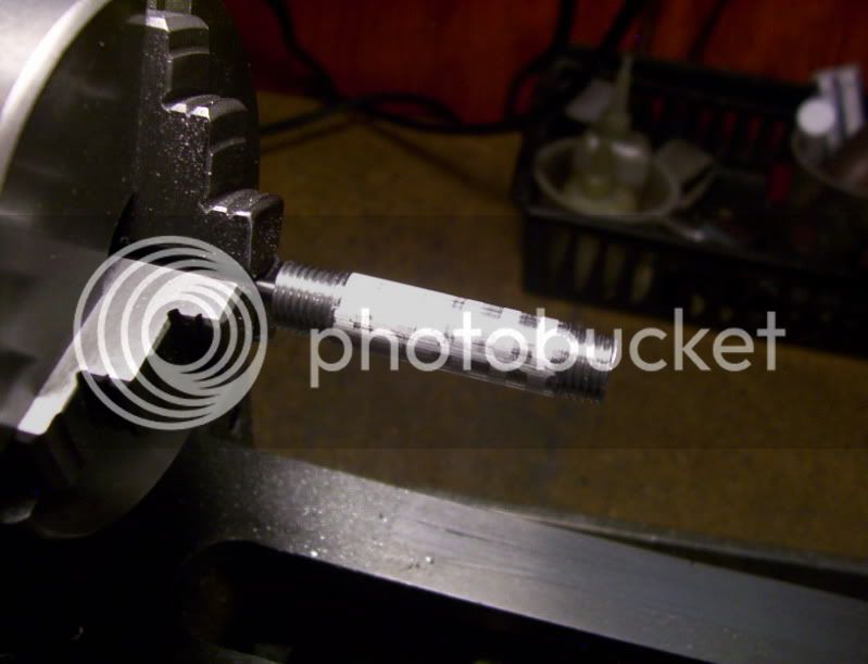
Then proceed to lock down the tailstock and use it as a horizontal press to press the rod into the piston blank.
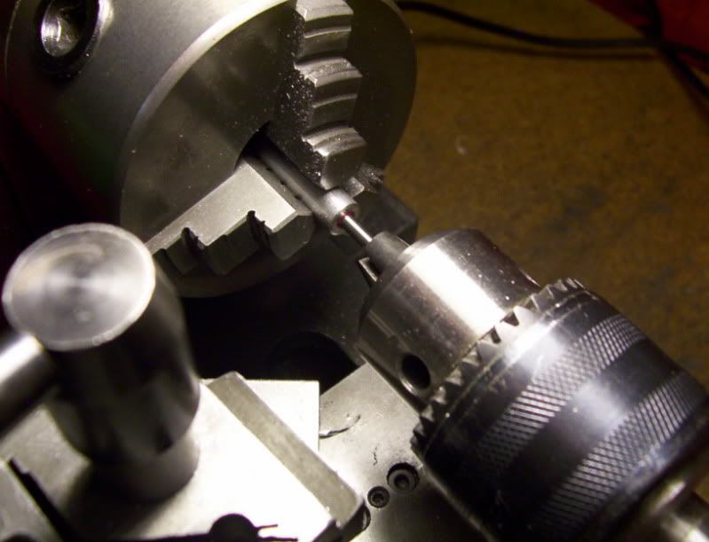
This ensures that the piston rod is going to be square in the piston blank.
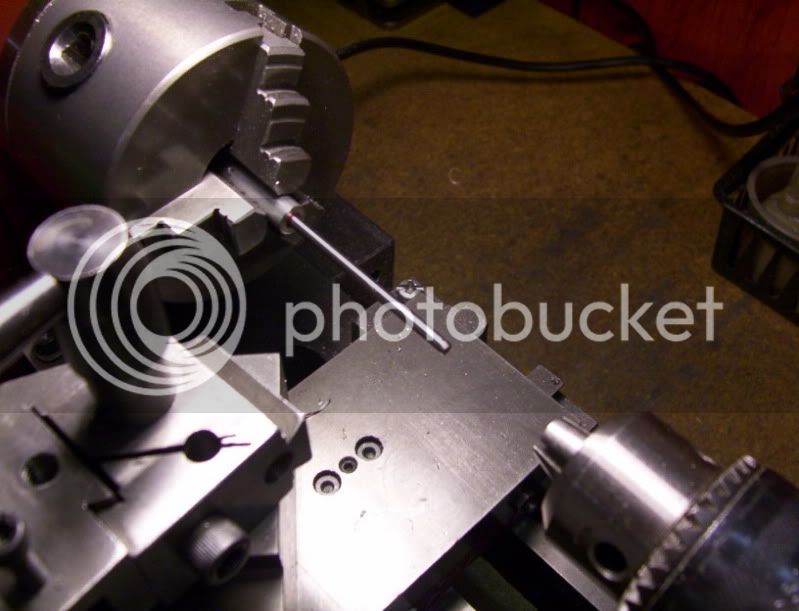
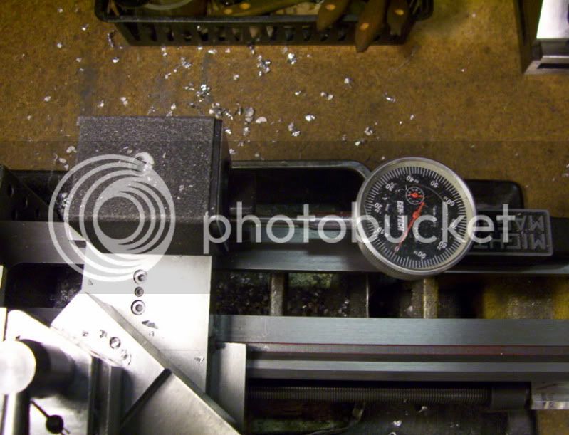
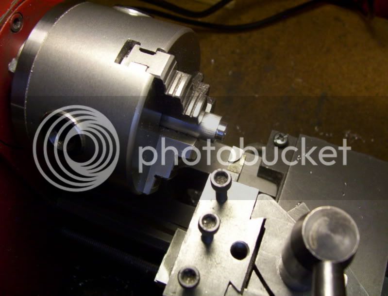
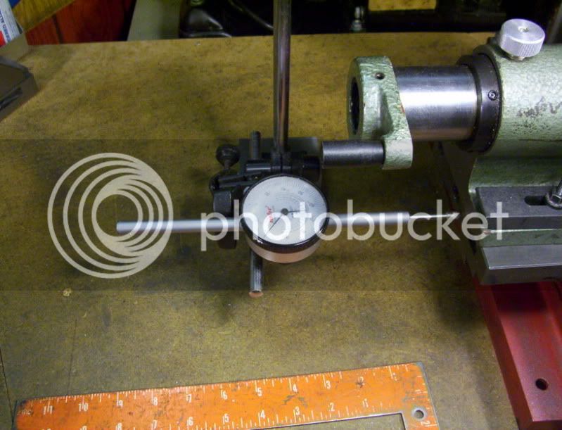
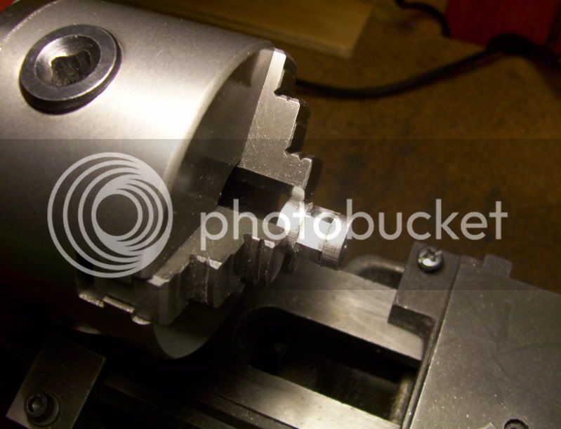
A good test is to run the lathe and check for any runout with the rod.
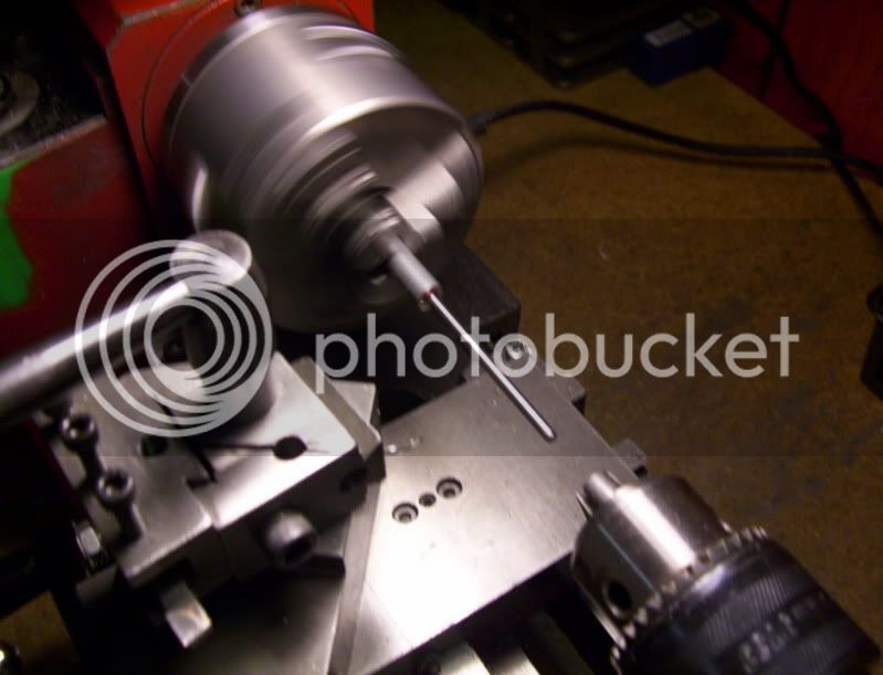
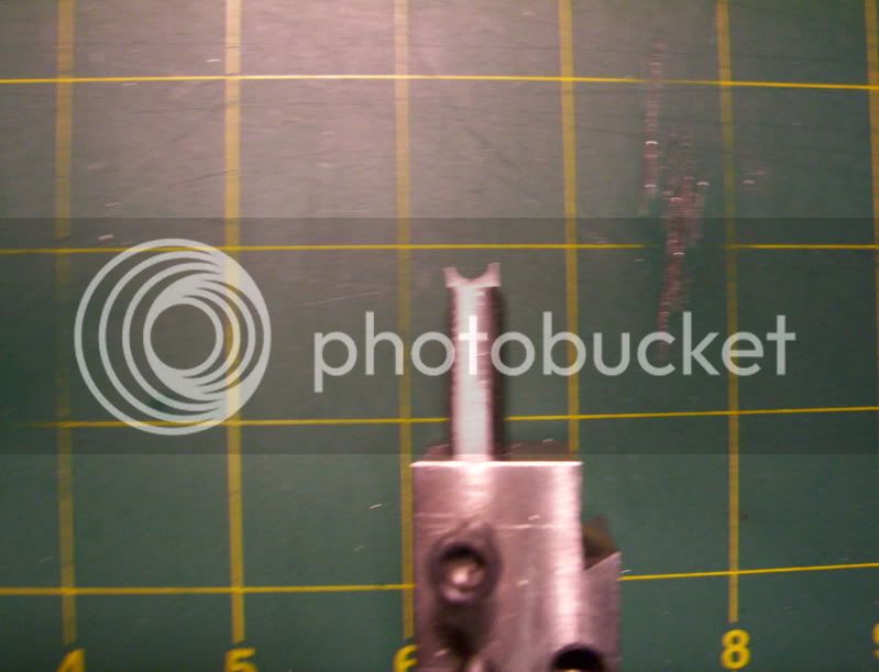
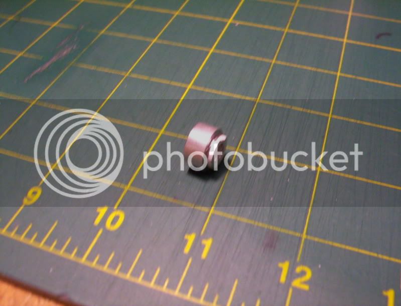
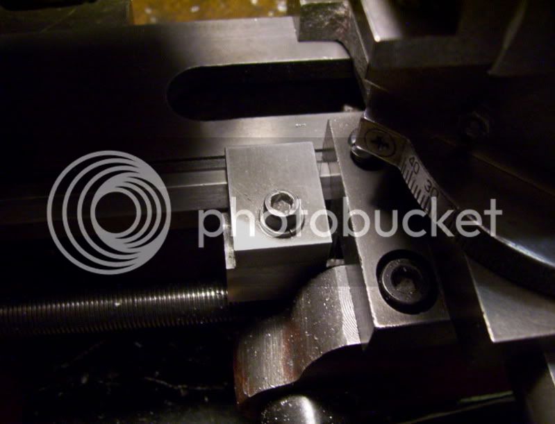
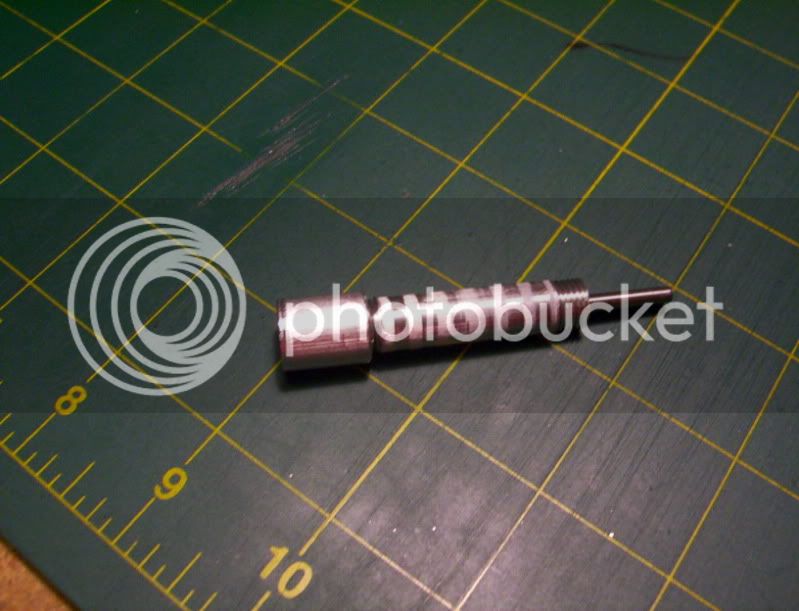
Then I mark it off where it needs to be cut off at and cut it to appropriate length.
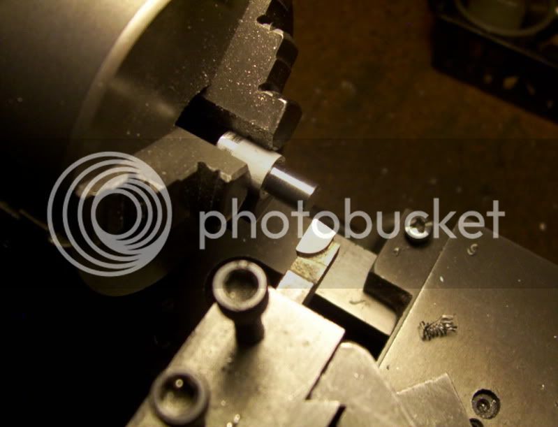
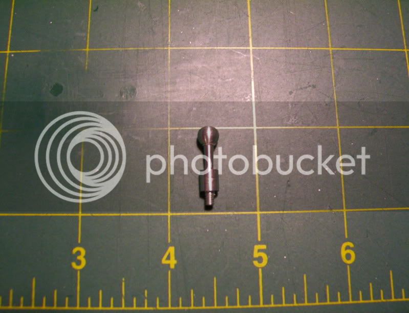
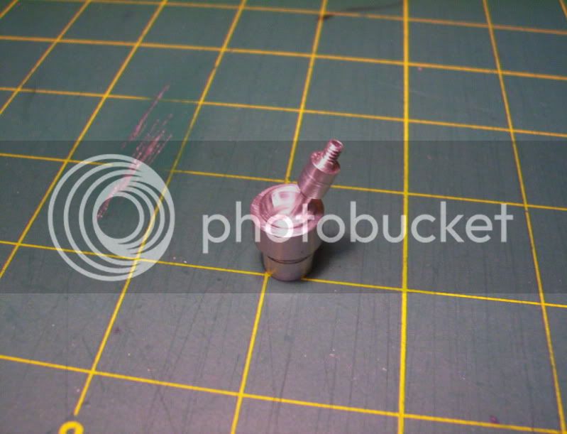
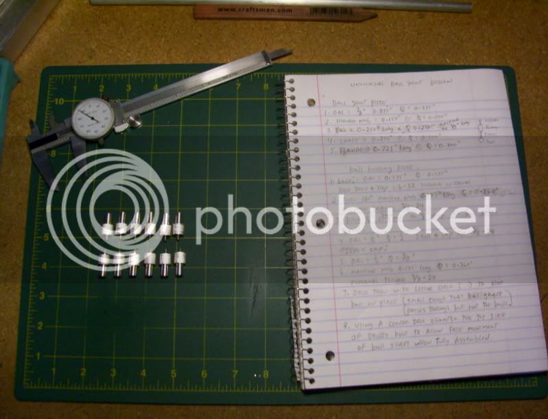
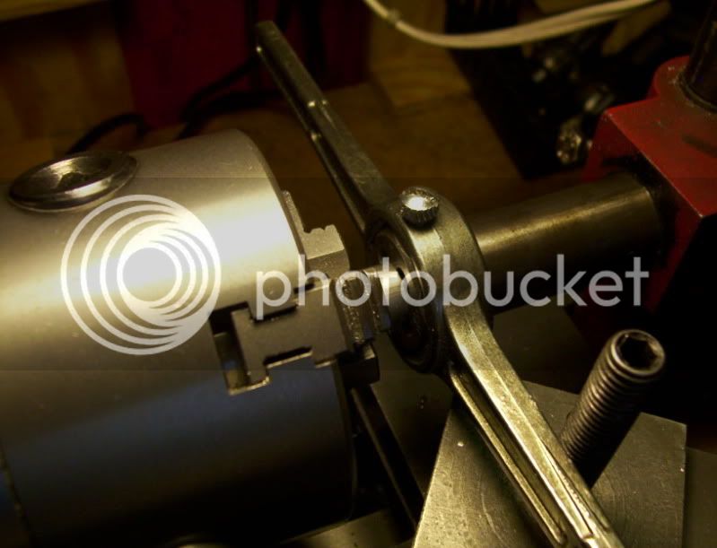
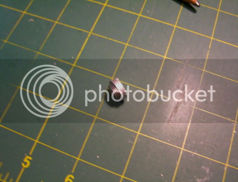
Then the rest is machinig the piston with facing cuts and logitudinal cuts until the piston fits the cylinder.
That's all for now, thanks for watcing.
This is a picture I found off the innernet, of a full size flight simulator,
I would like to try to make a very small miniature working mechanical model of it.
I'm approaching this with a different concept for the hydraulic cylinders, this time I'm building double acting cylinders, using only one hose connector, which will take care of both the push and pull of the piston. Also I' am machining the threads on the outside of the cylinder to hold the top and bottom endcaps, this makes it much more easier to fit the piston to the cylinder, as well as allows the total length of the cylinder to be made smaller with the same amount of piston movement, as when the threads were internal, as before.
I found a real nice way to make miniature pistons, by using loctite thread locker to hold the piston to the rod, and the use of my lathe as a horizontal press.
Here are the steps in making miniature piston and rod assemblies.
First I machine the cylinder with external threads and internal bore.
Then I face the piston stock, and begin with centerdrilling the proper size hole, for the piston rod.
Afterward I set up for the drilling of the rod,
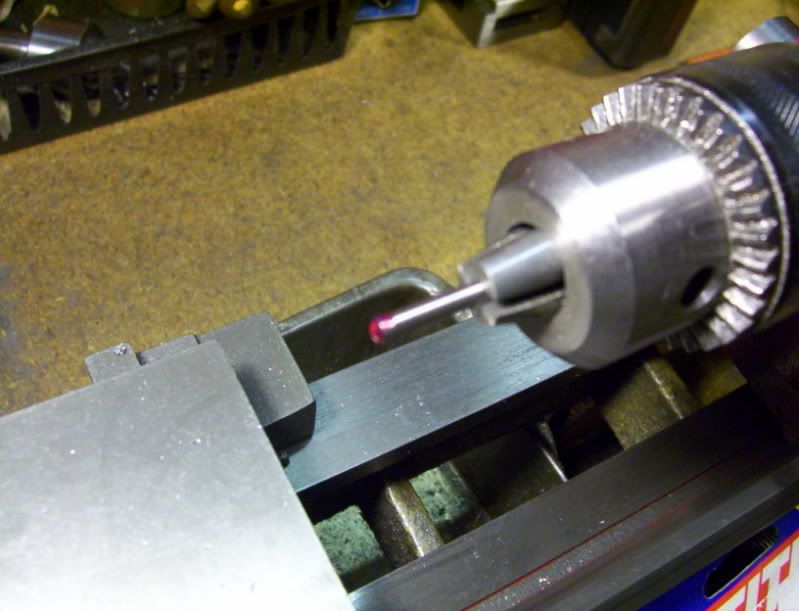
First, when ever you tighten a chuck key in a drill chuck, sometimes the drill will not line properly up straight out, and the bit goes on a slight angle bending its way into the preveiously drilled starter hole,
I stumbled on a way to make sure the drill bit and reamers ends up on target everytime, by loosly placing the drill bit in the chuck, locking down the tailstock then holding the bit in the starter hole, begin to tighten the chuck, tighten as tightr as possible, and now the drill or reamer is set to exact target of the starter hole.
Now I drill the hole to required depth for reamer to follow.
Then again with the reamer, I set it in the hole left by the drill and proceed to tighten the chuck.
Now back to the piston build.
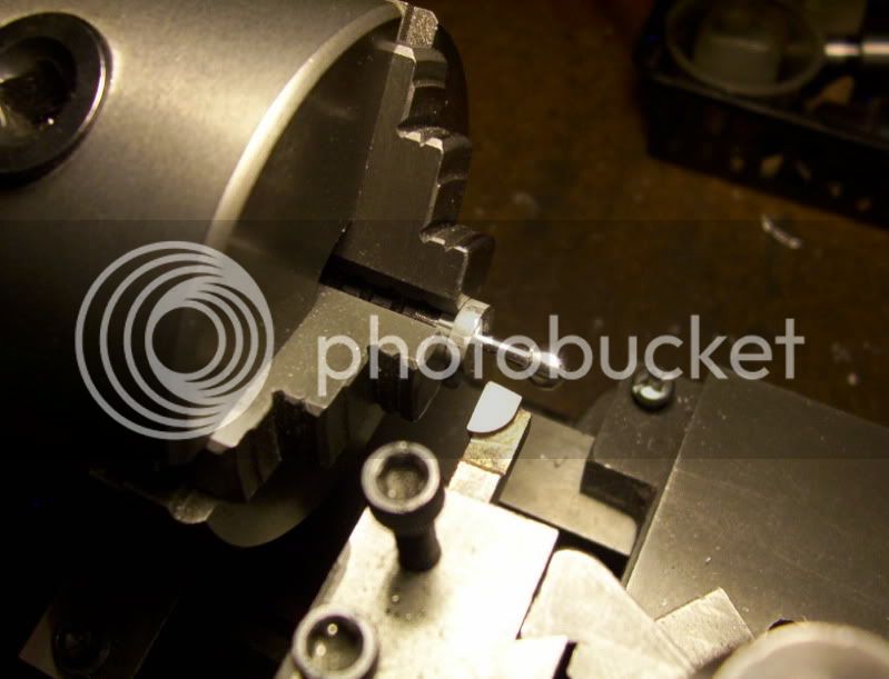
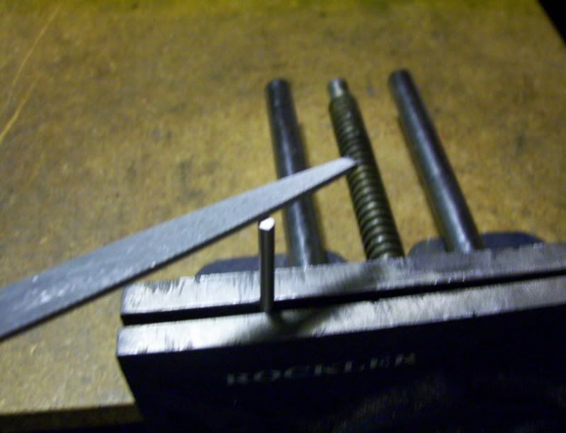
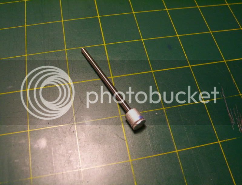
So Now the piston blank is drilled and reamed ready for it's rod, I then cut the rod blank, to appropriate length.
Then I file off the extreme large burr left by the sawing, to a taper that will allow the rod to slide into the hole in the piston, easily.
Then I take it back out and file the one end of the rod on top to give a slight burr hanging around its diameter.
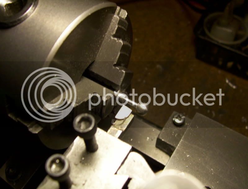
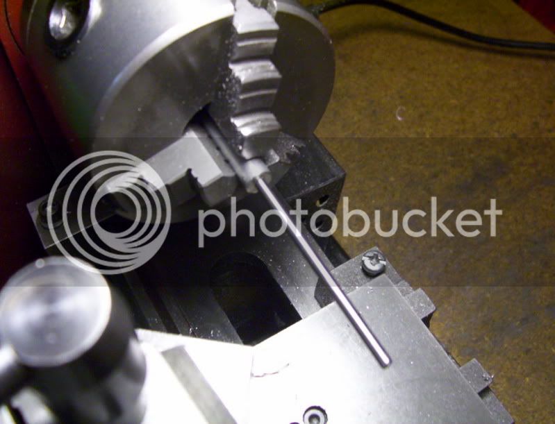
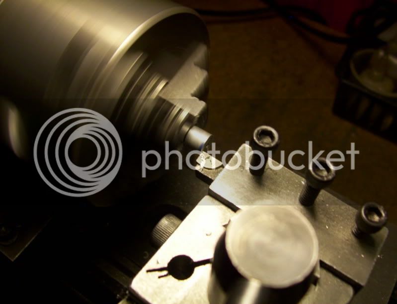
Now I place the prepared rod in the tailstock drill chuck with the end with the burr sticking out and tighten it and then add loctite glue to the tip of it.
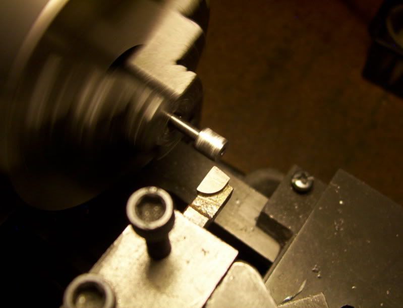
Then proceed to lock down the tailstock and use it as a horizontal press to press the rod into the piston blank.
This ensures that the piston rod is going to be square in the piston blank.
A good test is to run the lathe and check for any runout with the rod.
Then I mark it off where it needs to be cut off at and cut it to appropriate length.
Then the rest is machinig the piston with facing cuts and logitudinal cuts until the piston fits the cylinder.
That's all for now, thanks for watcing.