miniature model flight simulator

Home Model Engine Machinist Forum

Help Support Home Model Engine Machinist Forum:

This site may earn a commission from merchant affiliate links, including eBay, Amazon, and others.
I am completely impressed with the techniques and setups you are using on this project, Hobby. I'd like to thank you for photographically documenting each step and methods used, along with a detail of how you arrived at the final solution to a problem. Pictures always help me understand what is going on and I must say this build has been a fun one to follow along with. Please continue to put your talents on display for all of us to view. I particularly find that it is a huge benefit by supplying 'how to' ideas for future project reference. :bow:

BC1
Jim
 
Very unique choice for a project, just goes to show anythings possible if you set your mind to it! Keep up the fine craftsmanship!
 
Ron, Jim, and Blake

Thankyou guys, for the Very nice complements, and the very encouraging replies.

Have a great week.
 
Hi Jeff,

I have a small shop area, and that really taught me how to be more arganized. :D

Thanks for stopping by and the nice complement.

Have a great day...

---------------------------------------------------------------------------------------------

Hello,

The last post left off with the, beginnings of the oil hydron, that will couple the main line to each model cylinder, as one unt.

First the drilling of the two side spigot holes, these will later be cross drilled from the front of the workpiece to form the complete plumbing rout for each model cylinder.

256.jpg


After the drilling on both sides of the workpiece, then the rough profiling out of the spigots are done, in preparation for the finish form tool to be used to form the spigot.

257.jpg


Here I'm using one of the drilled holes as a reference to locate back to center of spigot hole.

258.jpg


Now the rest of the roughing out of the spigot.

259.jpg


some corner rounding to make it easier for the tool to work.

260.jpg


261.jpg


Now my benchtop drillpress has a strong motor on it, so the bullwork will be done on this more now, and save wear and tear on my milling machine.

In order to line up the workpiece in the vice on my drillpress, I get to dust off my homemade x,y, table, and finally put it to good use, after 10 years of being stagnat in a drawer.
Now the form tool is used.

[ame]http://www.youtube.com/watch?v=2hrzofU96nQ[/ame]

262.jpg


263.jpg


264.jpg


265.jpg


Now time to verify the angle of the base that this will connect to, and set the angle vise to 60*, for roughing out the front spigots.

266.jpg


267.jpg


Some locating and edge finding, to locate the center of the workpiece for reference.

268.jpg


But first before I tighten the vise, I need to align the workpiece so the 2 side spigots are parrallel to the table. What better way to do this then to use a guage on a surface plate, to check height of the two side holes center.

269.jpg


270.jpg


some measuring for calculating center, and the workpiece set on course, with edge finding.

271.jpg


272.jpg


Drill the next spigot holes one on each side of the front face.

273.jpg


274.jpg


275.jpg


And again roughing out work.

276.jpg


277.jpg


278.jpg


279.jpg


280.jpg


281-1.jpg


282.jpg


283.jpg


Now back on the drillpress, to form the spigots, to finish dia.

284.jpg


Locating centers of holes.

285.jpg


And the formed spigots done.

286.jpg


287.jpg


Thats as far as I want to go for now, this first piece is made to check angles and holes alignment as was drawn up to make sure no calculations were wrong.

I now need to make the other two, and get them both to this stage also, because all three will then be profile milled to bring the workpiece to a proper shape, so this can be done when all three are being worked on for consistancy.

Have fun in the shop...
 
That is some amazing stuff Hobs. You have a great ability to see inside the bar of aluminum, and remove everything that is not the part. Great job.

I like the bases for the cylinder's. There is a lot to think about with all those angles, and I like your solution.

Kel
 
Hi Kel,

Thanks for the complement,

Those bases that the cylinders bolt to, was probably the most dificult part to figure out, with this whole project so far, I went through 6 pieces trying to figure the angles, as well as the orientation of the part.

I knew what I wanted in angles, but I just couldn't get the part oriented in the right direction, then once I did, then my angles were out of whack, finally after some trial and error, I got the compound angles exact.

The solution of using a wooden jig, I find that wooden jigs if made properly and sturdy, are easier and quicker to make, and much less material cost, then making them out of metal, when a wooden jig is feasable to use in particular aplications.

Thanks again for looking in,
Have a great day...
 
Hi Hobby,

Did you get your mill fixed again? I guess so because the pictures of progress are rolling in again. Very nice work! :bow:
Like the wooden jigs you made, simple cheap and they do what they need to do!

Have fun, regards Jeroen
 

Hi Jeroen

Yeh, it needed another speed controler.
Thanks for the complement.
Nice thing about wooden jigs, there quicker and easier to make and once your done with them they can be discarded, easily.

-----------------------------------------------------------------------------------------------------------

Todays session was more about fixing mistakes.

I was making the roughed out spigots (square posts) too large, I made them 1/4" square to fit the larger formtool, for larger dia. tubing.

This project calls for smaller dia. tubing, so I was using the smaller formtool, on the mistakenly large square posts, and end up breaking the form tool, as well as messing up the workpiece.

288.jpg


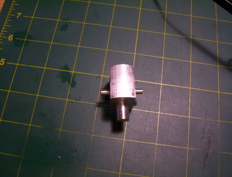
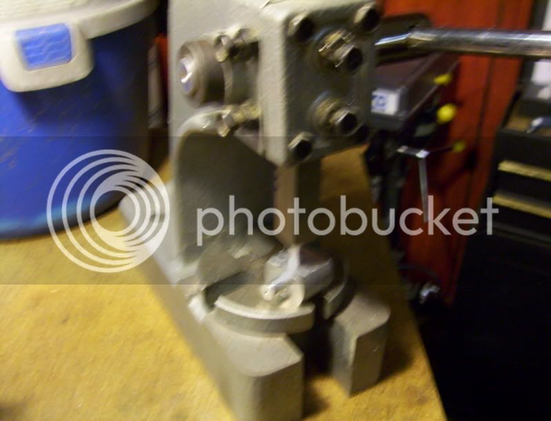
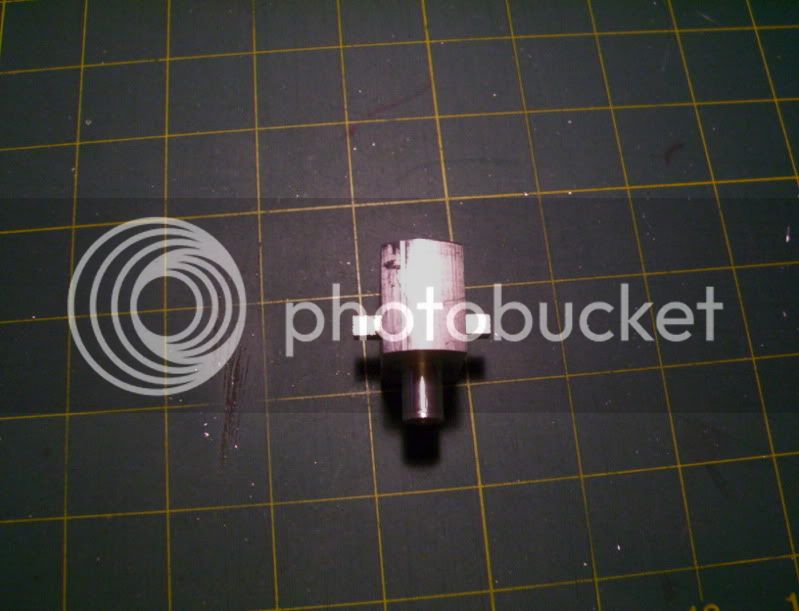
So after some careful thinking, instead of making a new workpiece, I decided the best way to fix this would be to cut off both ruined square posts, and set it back up in the spin jig, drill for a plug, then remachine the plug to the proper square post size.

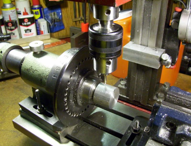
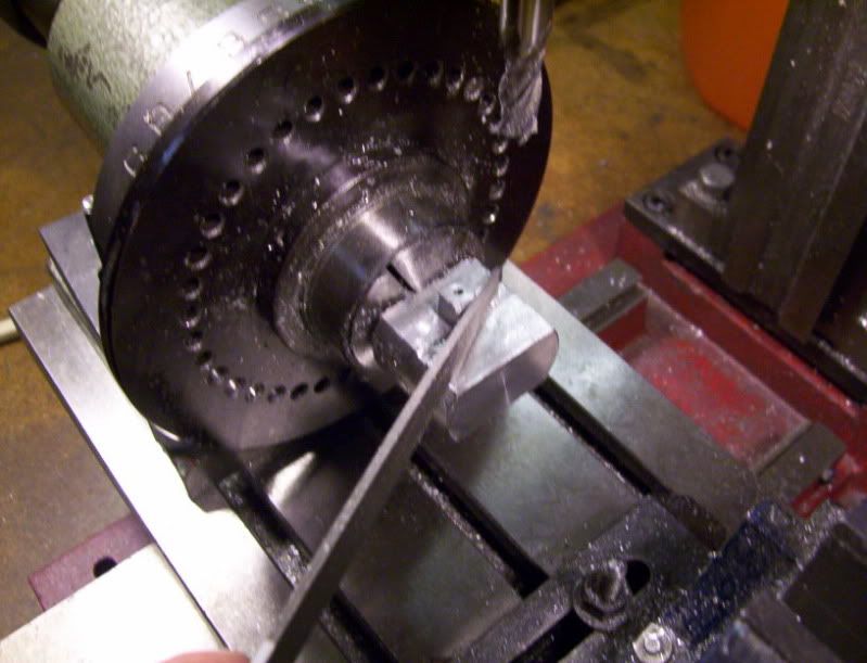
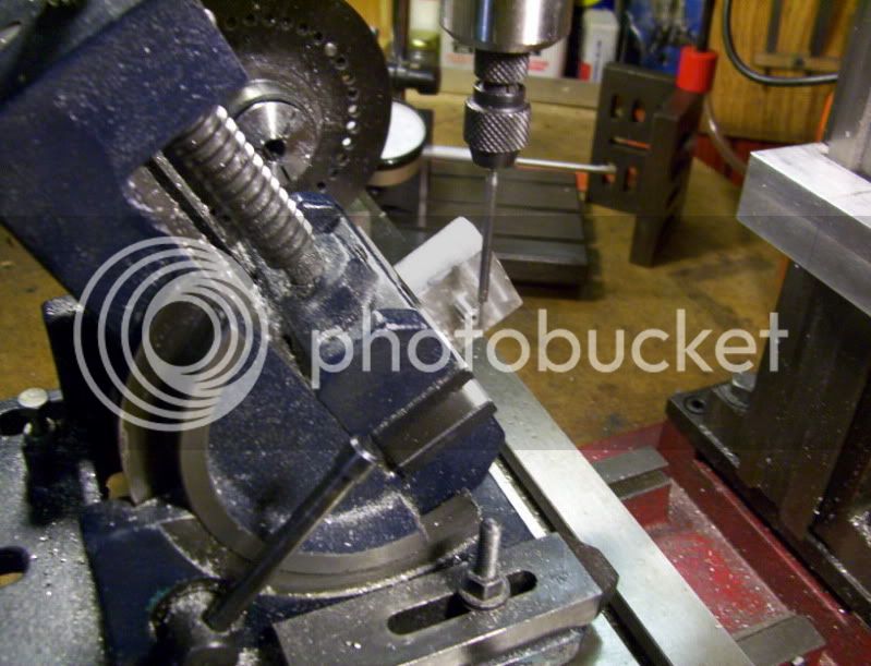
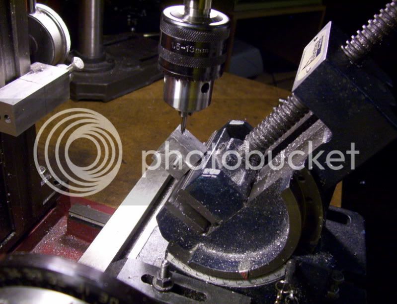
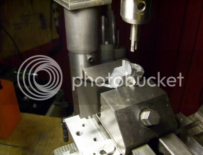
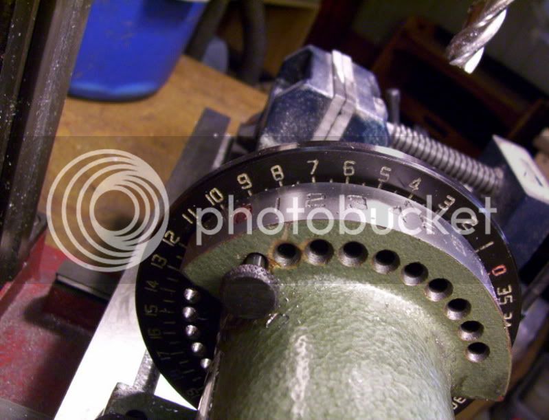
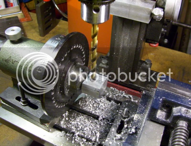
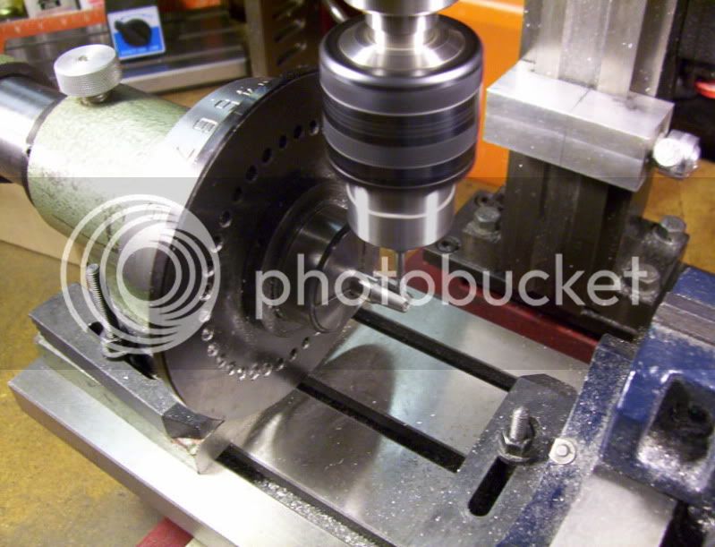
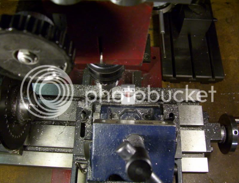
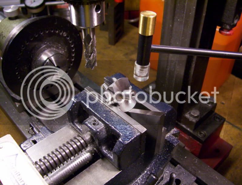
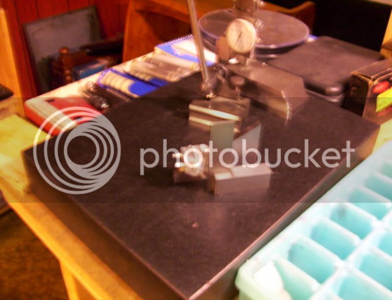
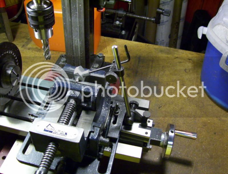
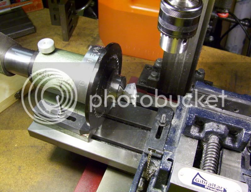
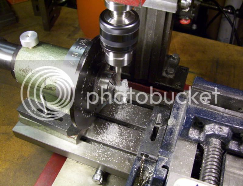
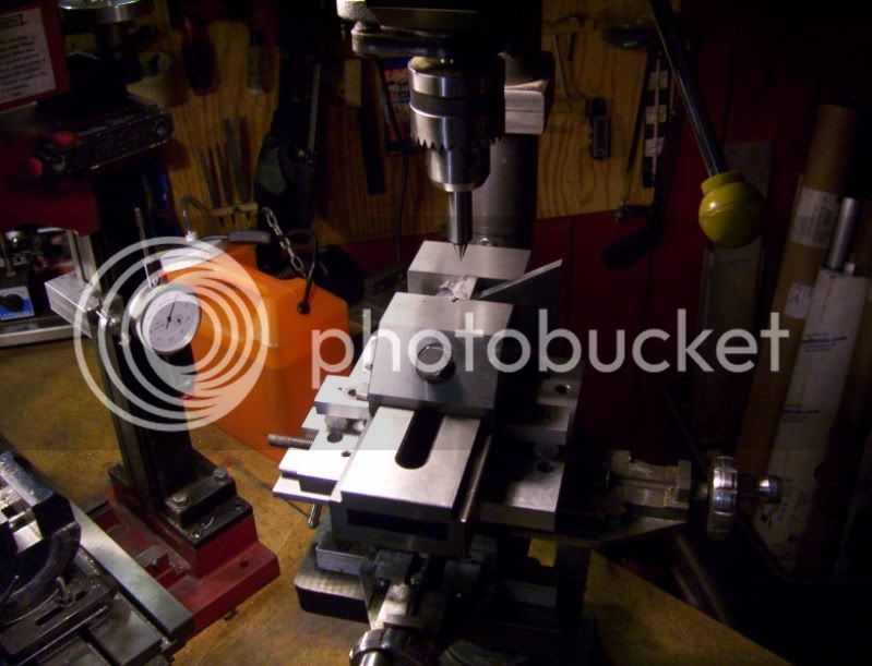
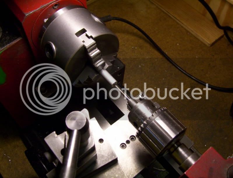
So first I turned the spin jig, to 90*,

289.jpg


by doing this I can reinsert the workpiece on the vertical, and use a square to line it up square to the table surface.

290.jpg


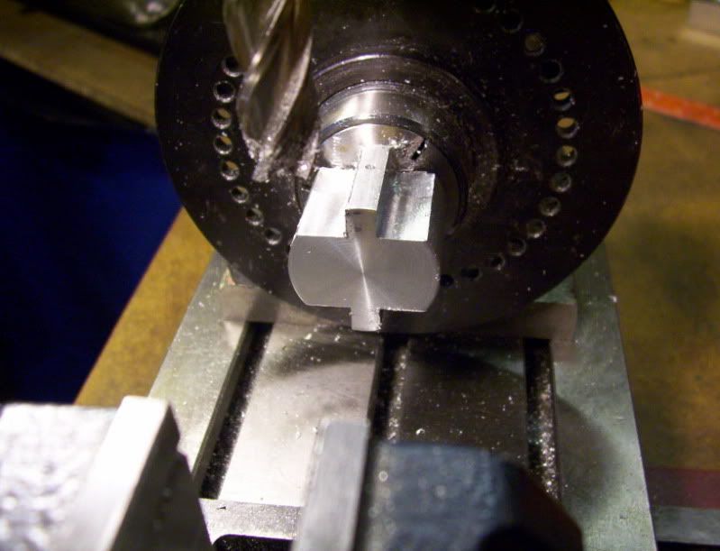
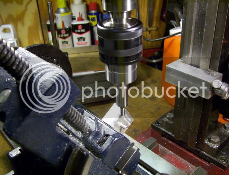
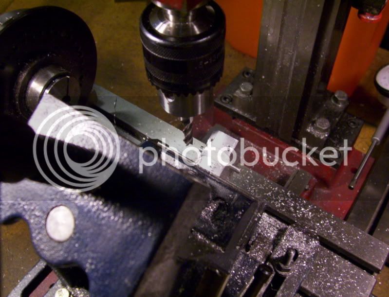
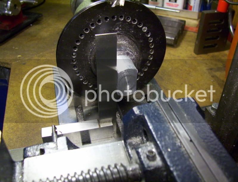
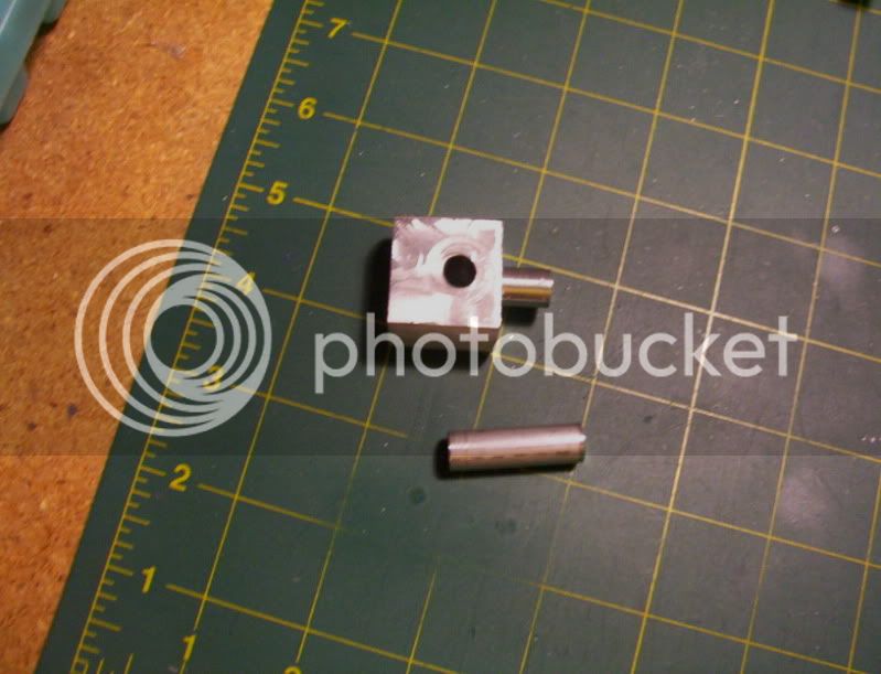
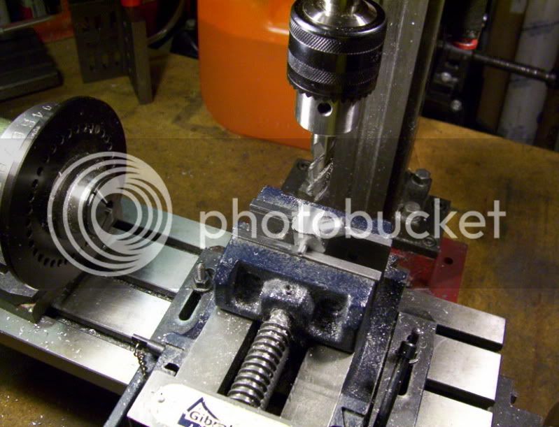
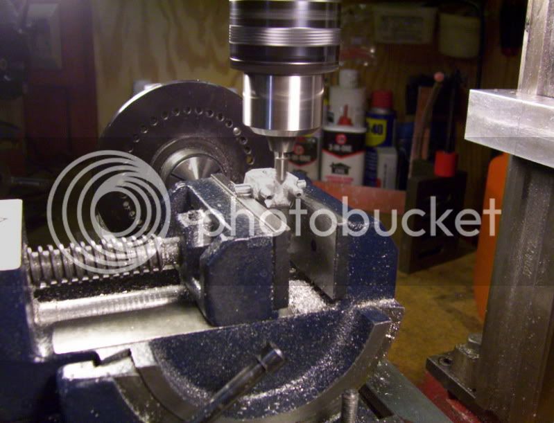
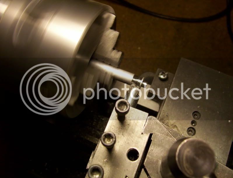
from there, I proceeded to machine off the one bad stud,

291.jpg


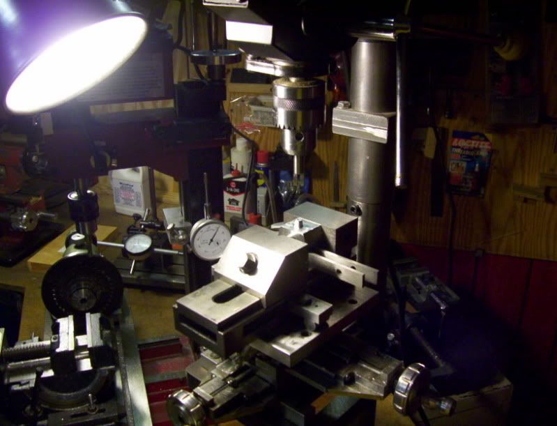
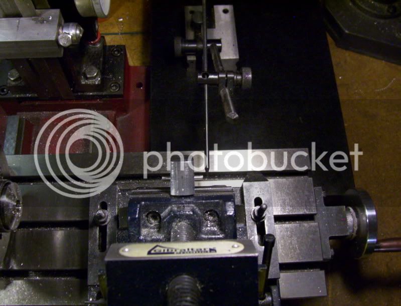
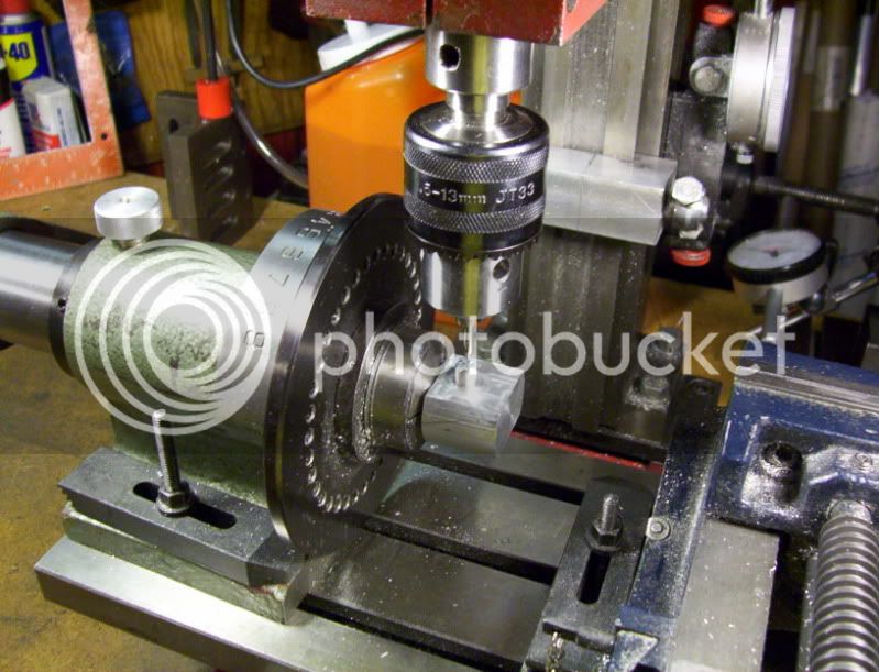
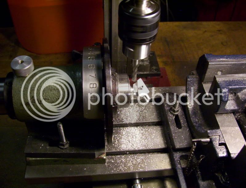
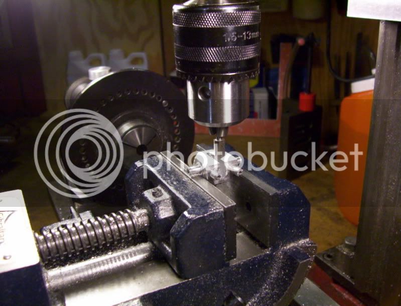
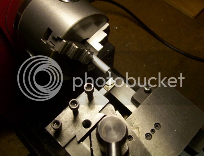
Then using a center finder I located the original drilled hole.

.
292.jpg


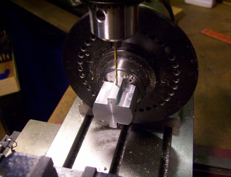
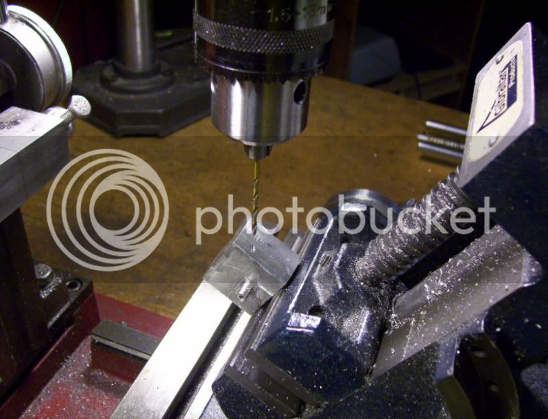
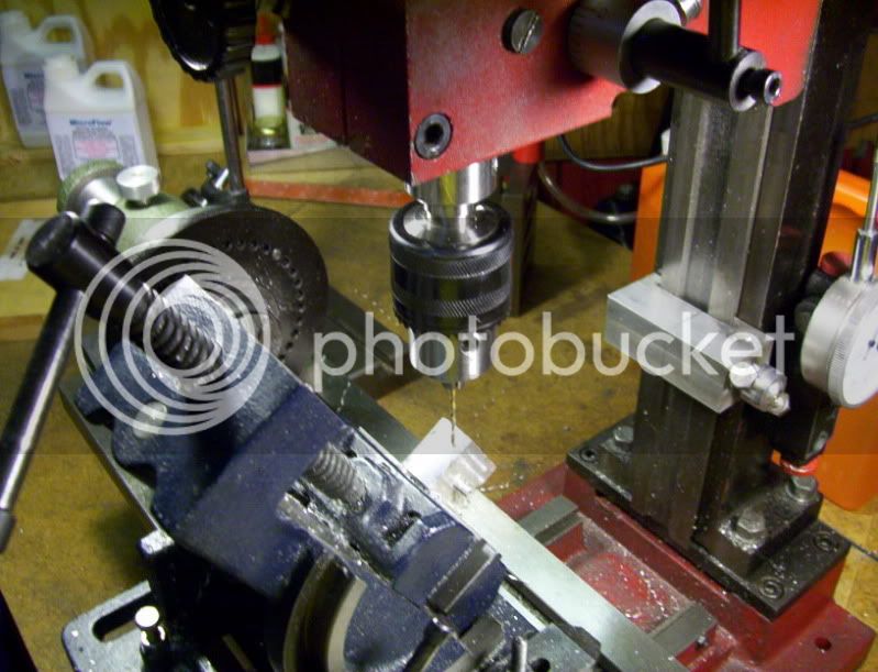
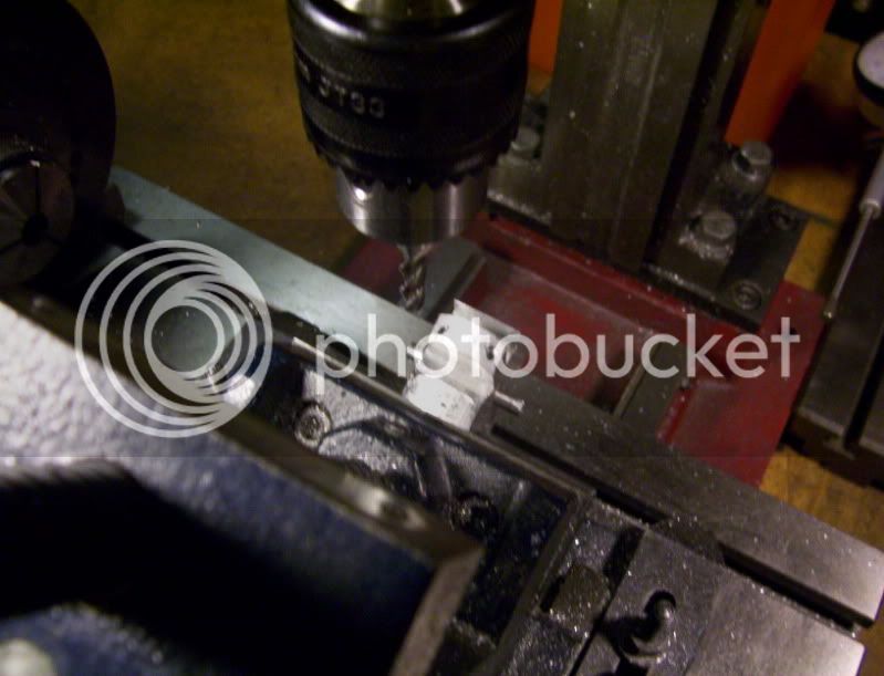
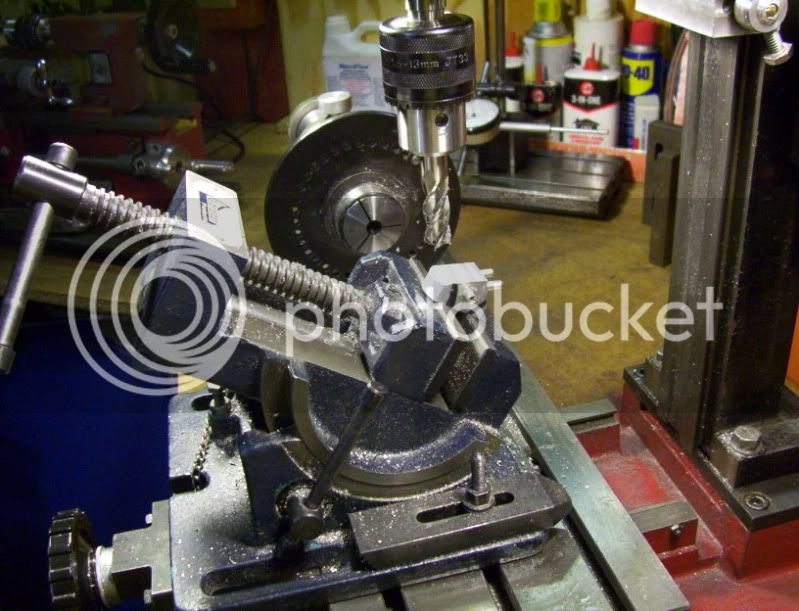
And used a 5/16" drill to make a thru hole.

293.jpg


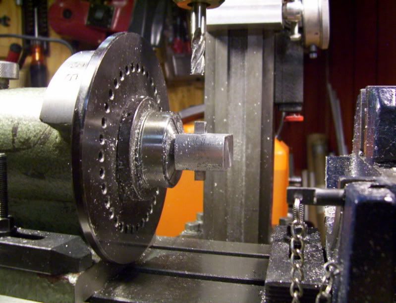
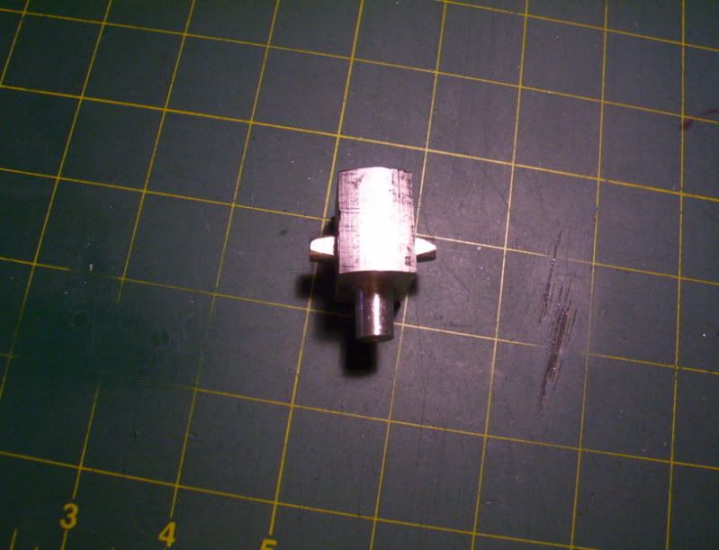
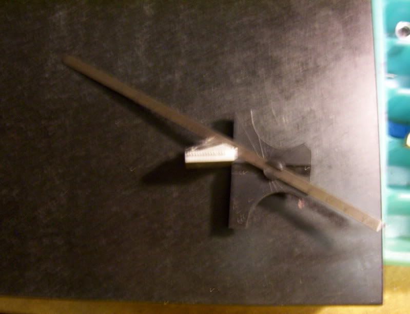
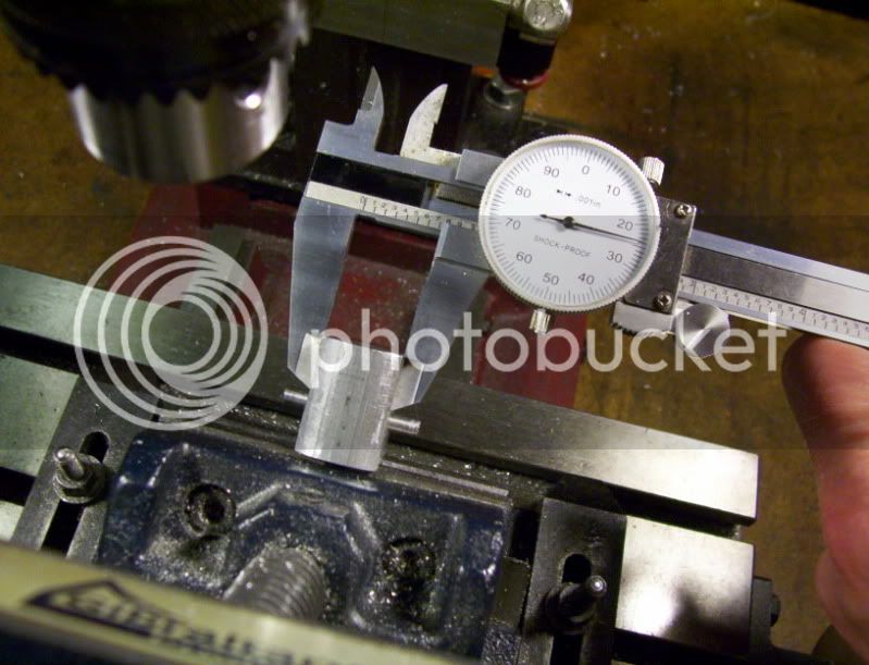
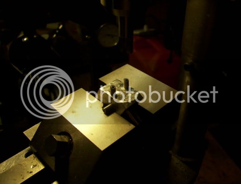
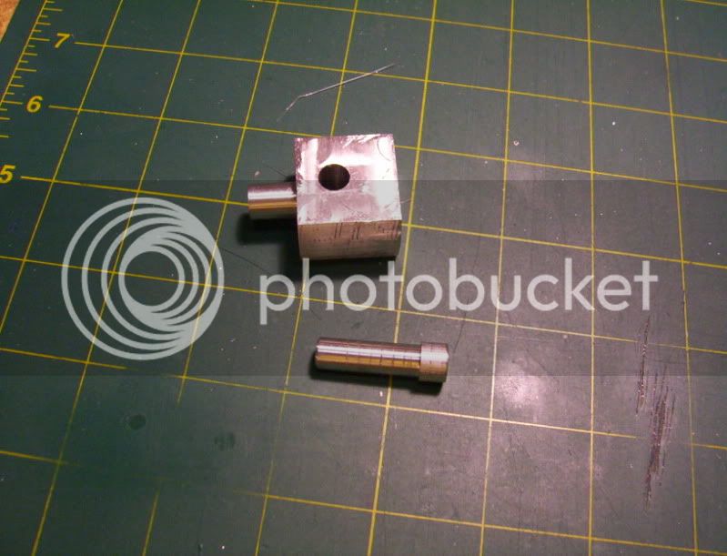
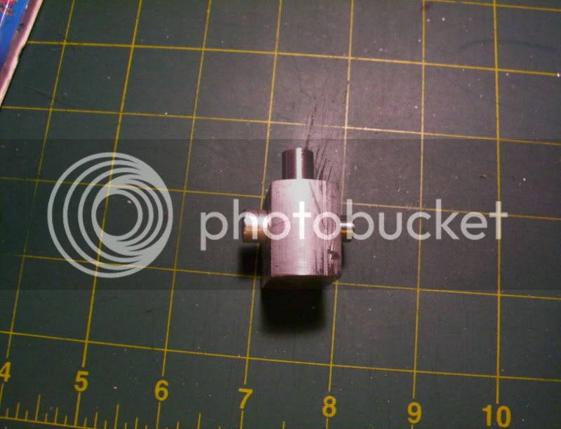
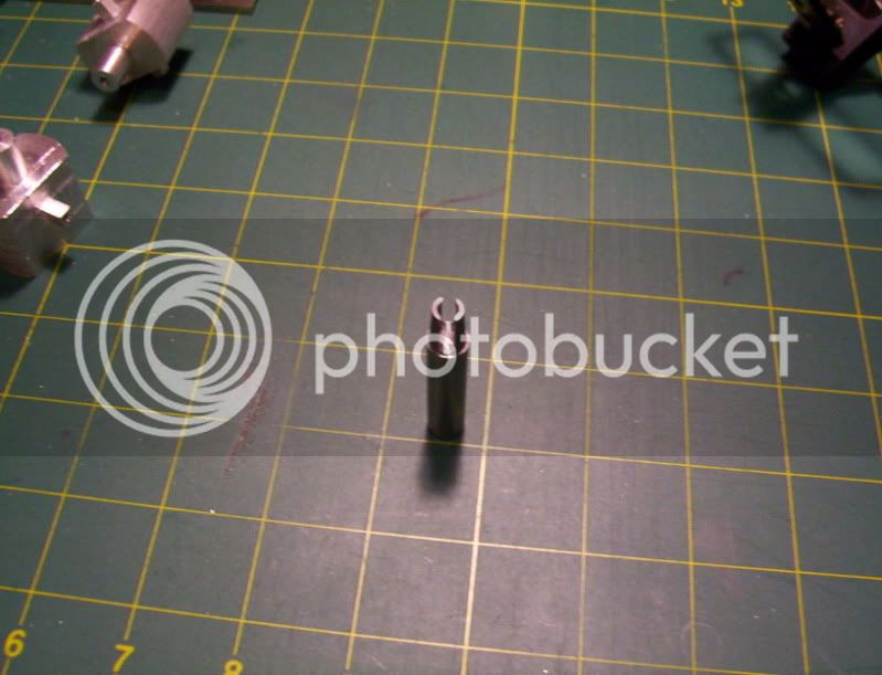
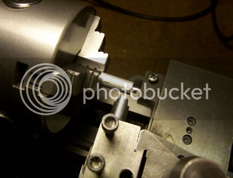
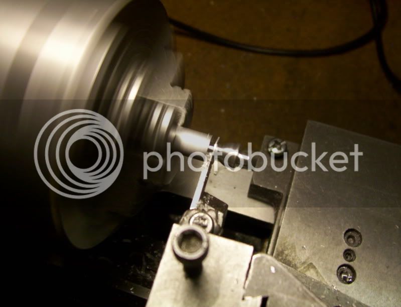
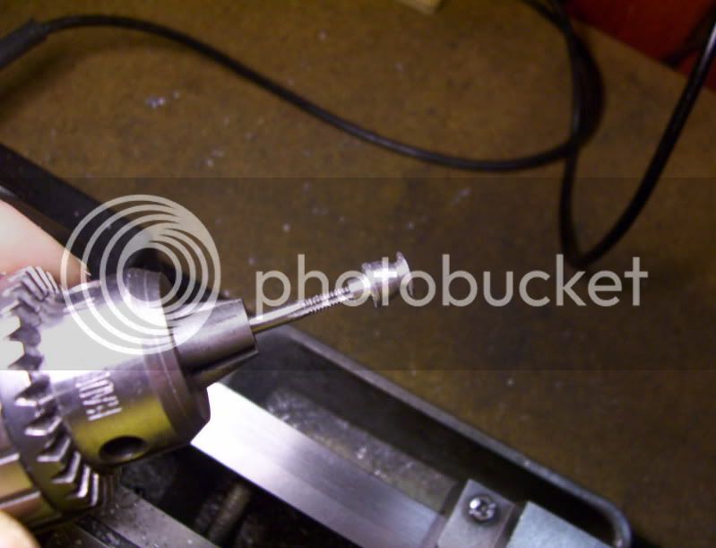
Then took a piece of 3/8" dia. dowle and machined it to the proper dia, to fit the drilled hole, leaving 1/4" in heigth left as a shoulder, to press fit into the workpiece.

294.jpg


295.jpg


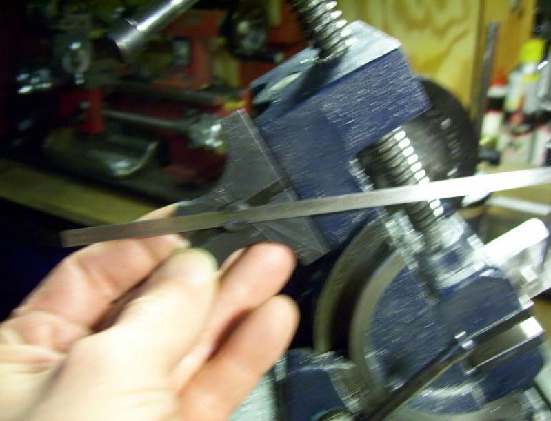
While it was spinning in the lathe I took a file and set it on edge to make some ring grooves, that will be used for keying in for the loctite glue.
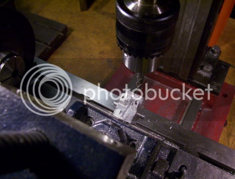
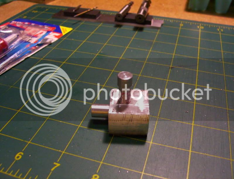
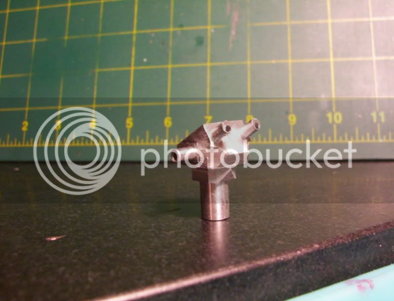
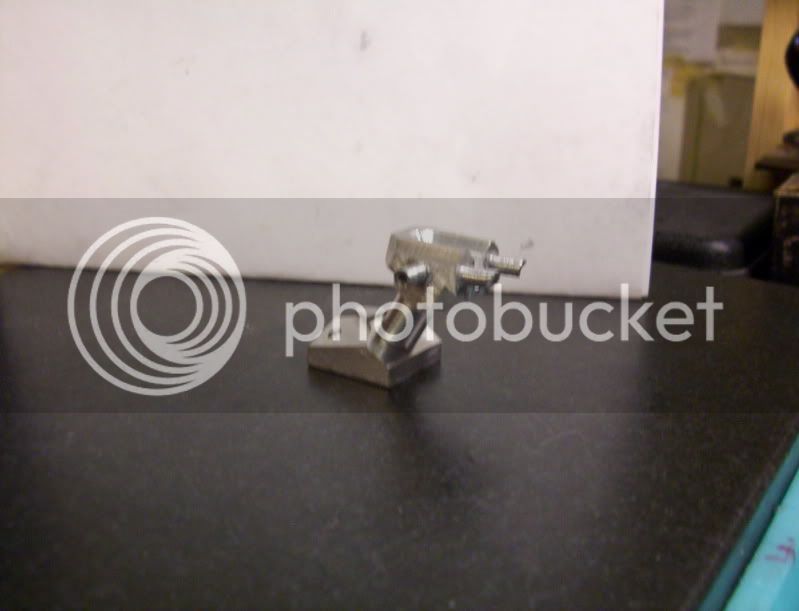
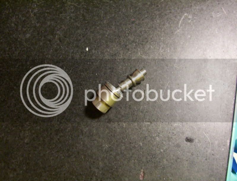
296.jpg


Pressed it in.

297.jpg


298.jpg


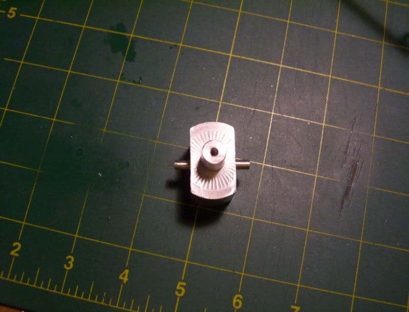
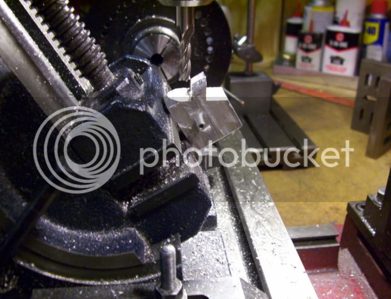
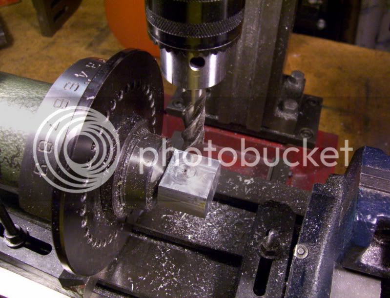
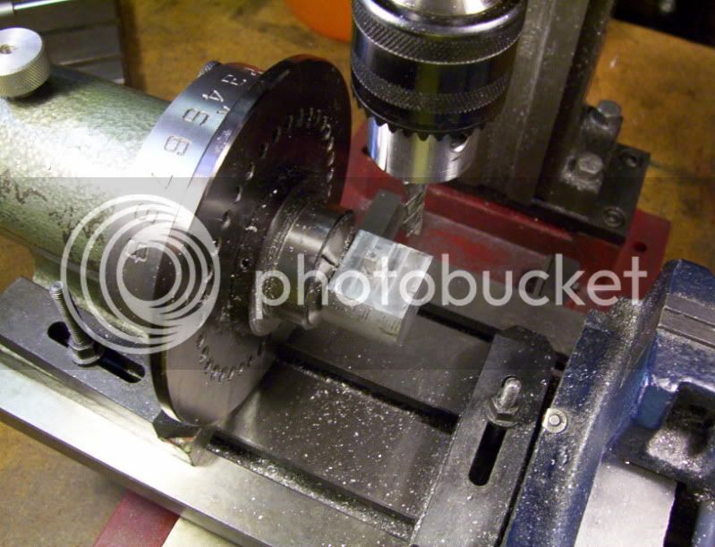
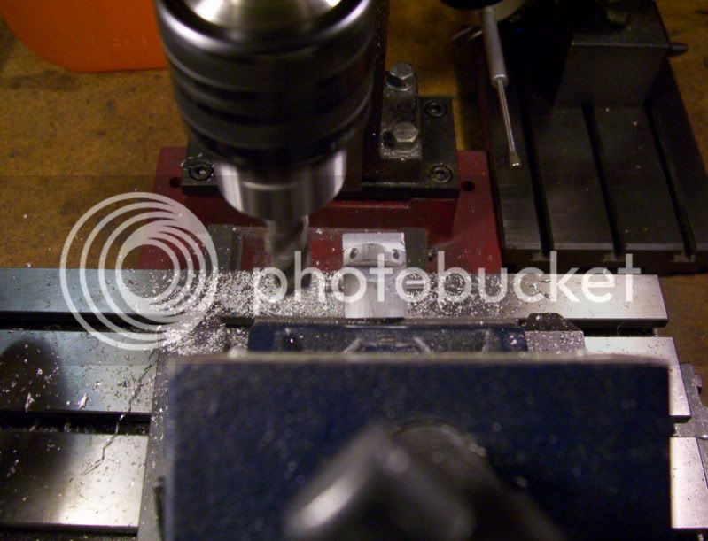
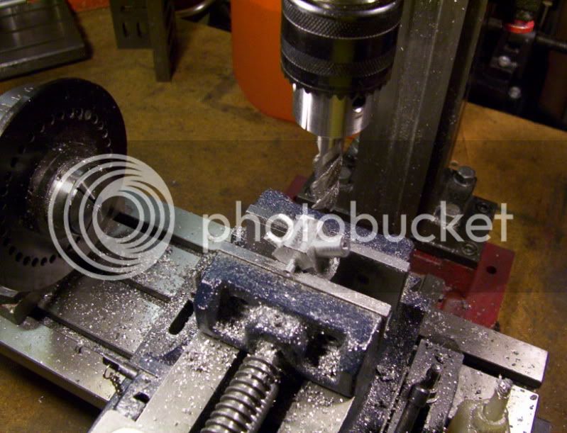
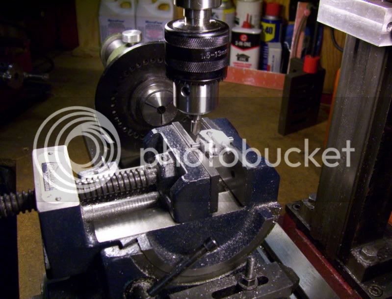
Then redrilled, and remachined to get the proper size square post.

299.jpg


300.jpg


301.jpg


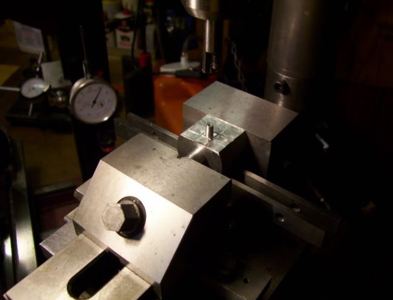
Ok now time to make a new formtool, however this time I'm making it more like a cutter/formtool,
by offsetting the endmill cut off center allows the endmill to cut a somewhat sharp edge on the tool.

303.jpg


304.jpg


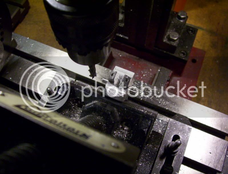
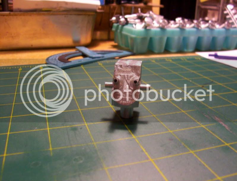
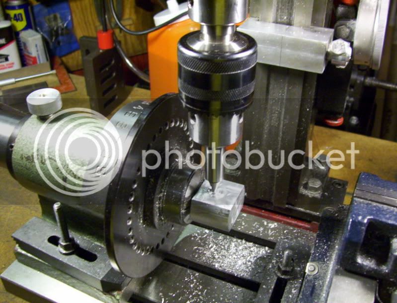
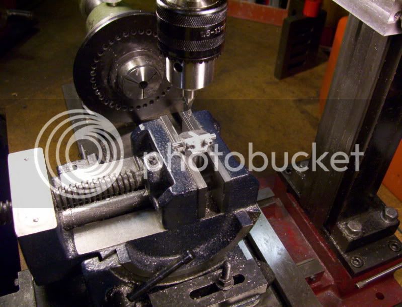
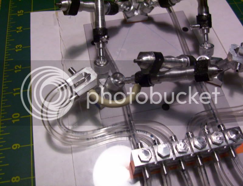
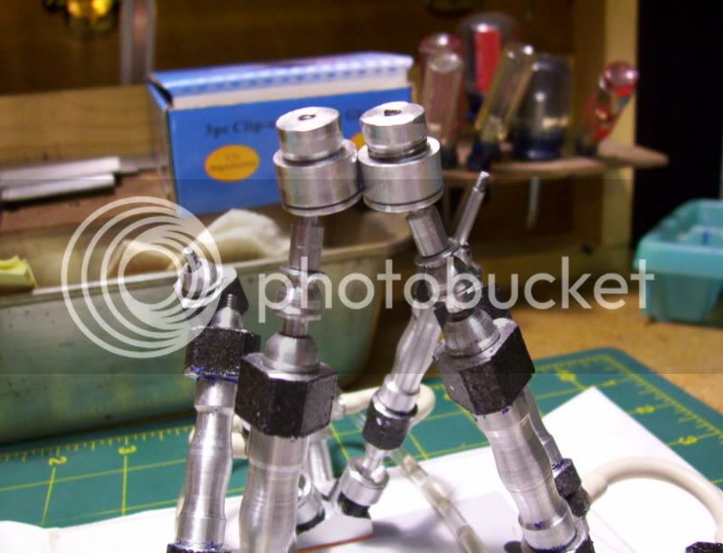
After forming the spigots on both sides, I'm now ready to continue on where I left off before the tool broke and ruined this workpiece.
Now I can machine the front face 2 spigots.

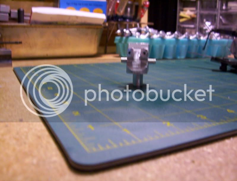
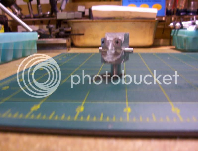
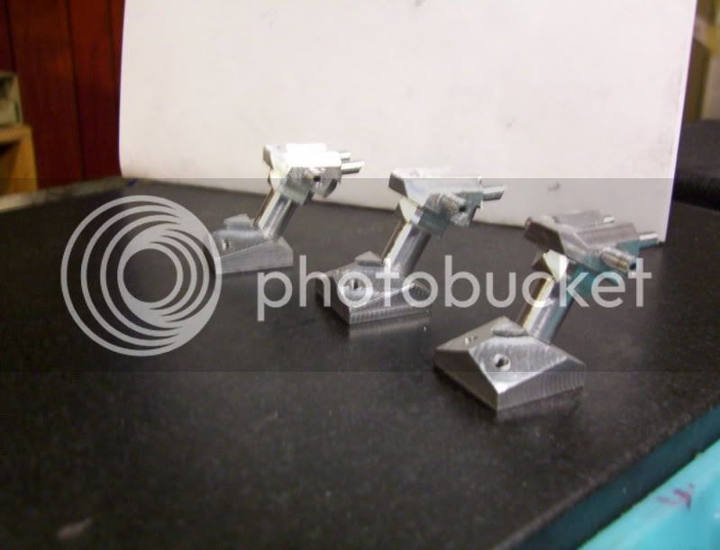
The more machining I do on this piece, the more it smiles at me.

305.jpg


307.jpg


By making and fixing this mistake, has been again a Blessing in disguise, because I now see ways where I can use this method to make complicated parts where facets will be protruding and things, instead of machining it out of one solid piece, and making my little mill do alot of roughing bullwork,
I can dowle and glue pieces together that are close to finish size, then use my mill to machine to final profile dimensions, as if I were machining a casting, this way it would save a lot in material cost, plus I could use pieces of scrap to build up larger parts for final milling.

Another advantage would be, those difficult areas to machine could be almost eliminated, because I could machine certain areas before I fit and glue more pieces, in the area, I see great potential in using this method of building up pieces for a finished part, then machining to finish dimensions.


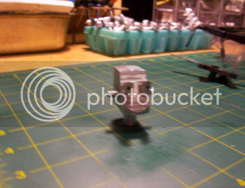
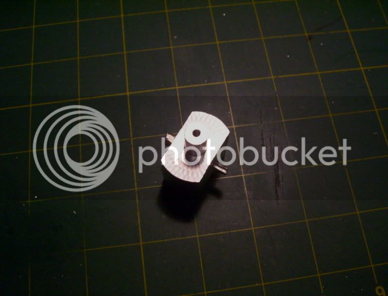
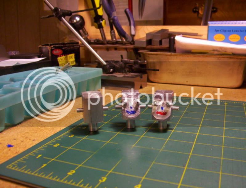
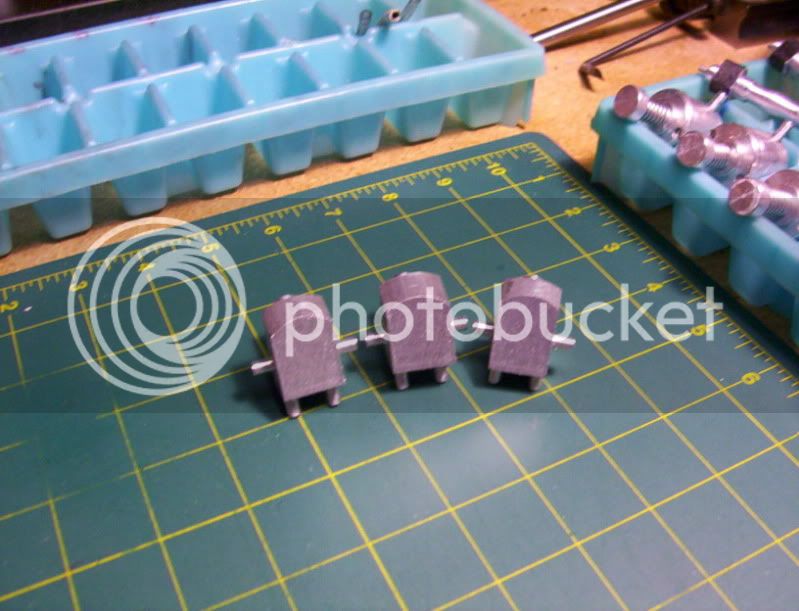
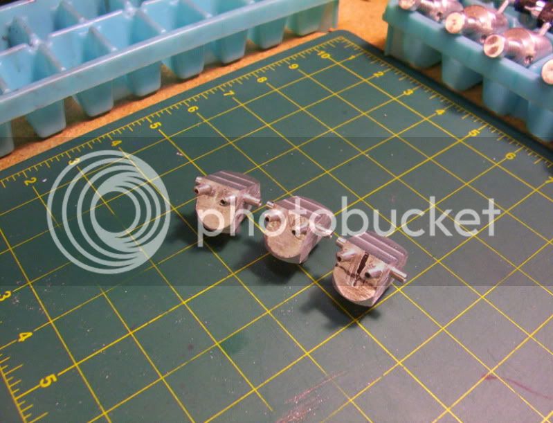
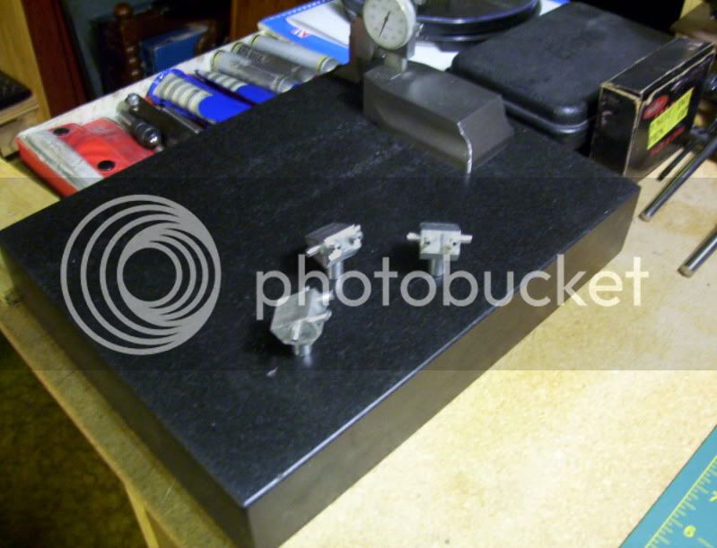
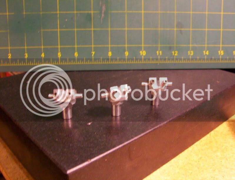
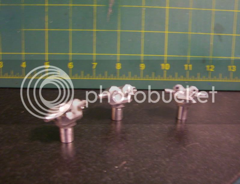
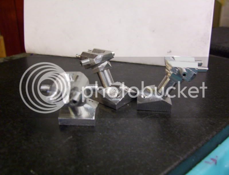
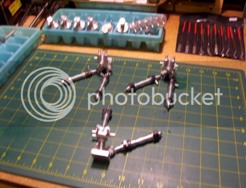
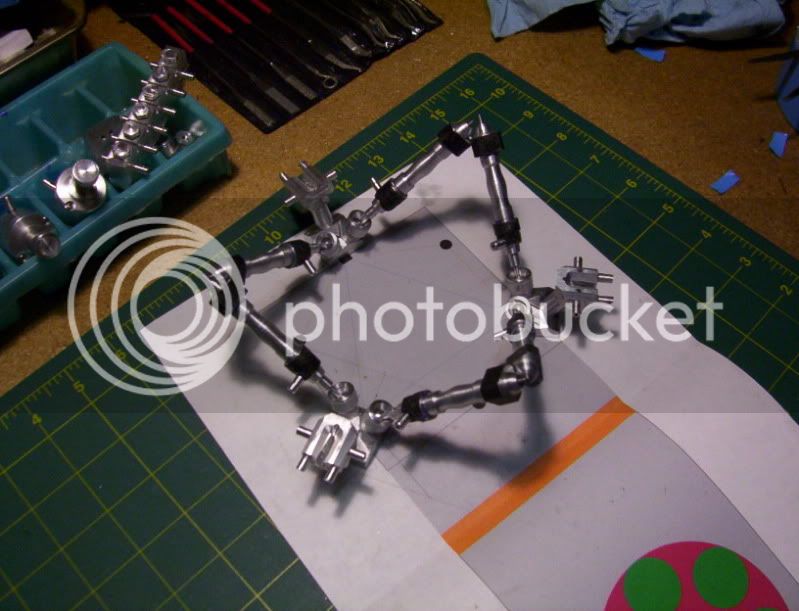
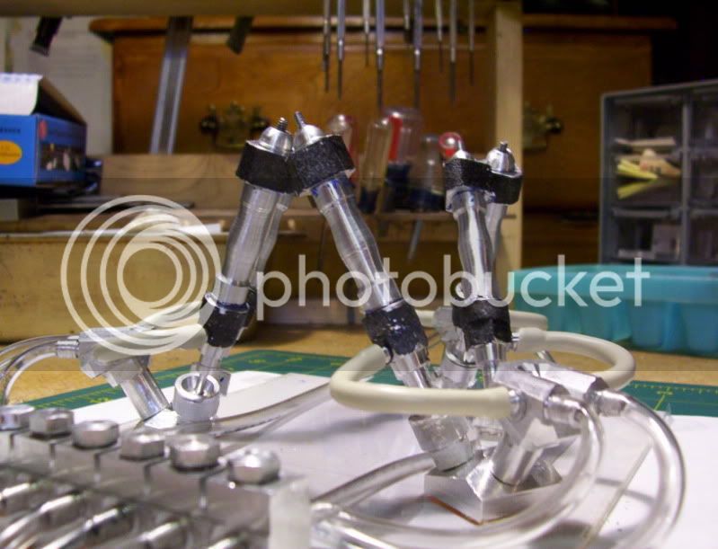
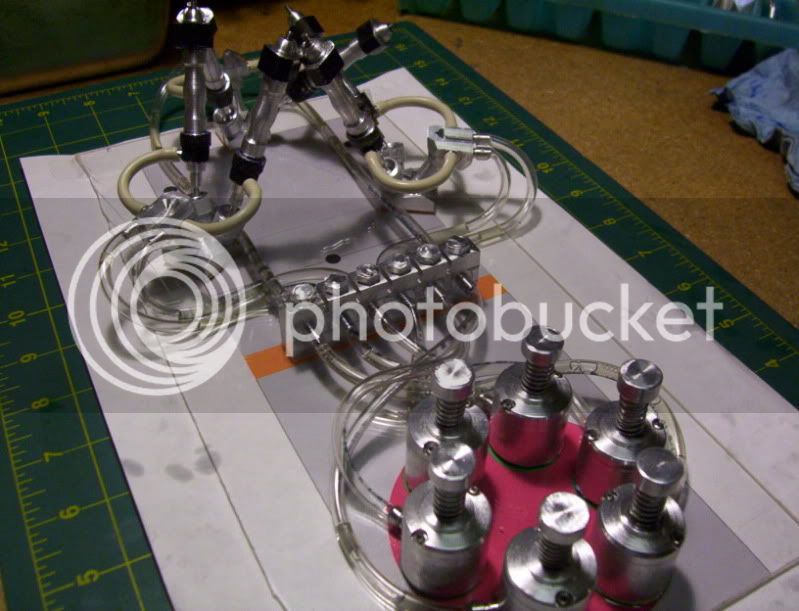
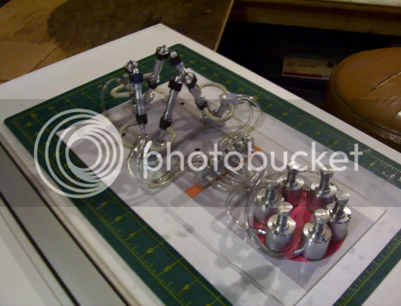
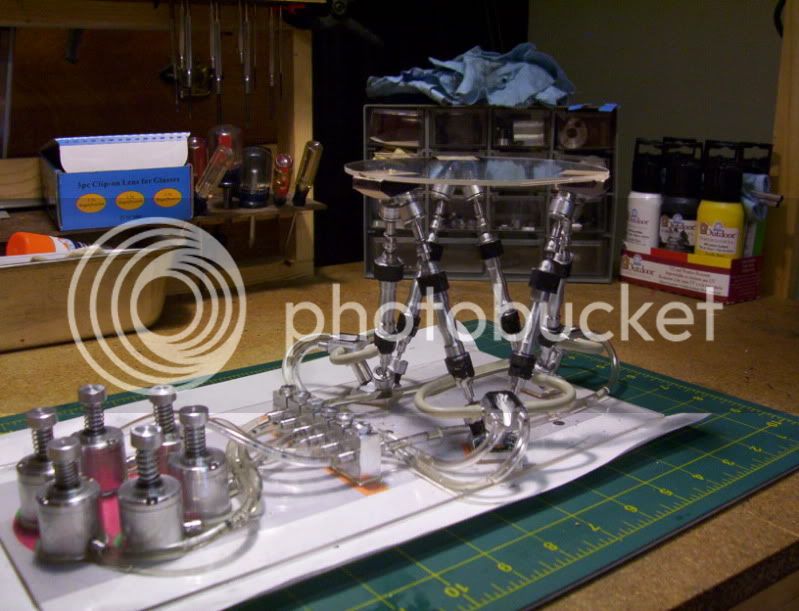
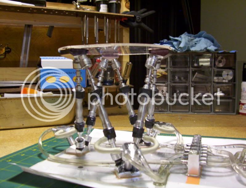
So anyway 2 of these parts finished one to go.

308.jpg


Have a great day...
 
Last couple of evenings been working on the oil hydrons.

First using my benchtop bandsaw, a cut the tops of the workpieces, so as to machine the tops to finish dimensions.

309-1.jpg


310.jpg


311.jpg


Then set it aqt a 30* angle to start profiling the front skirt.

312.jpg


313.jpg


Layout the back angle cut.

314.jpg


and setting a surface guage so as to lacate the next 2 workpieces at the same angle.

315.jpg


And machining the backside skirt.

316.jpg


and the 3 machined to that point.

317.jpg


Now some more profiling around the skirt to give it some 3D depth.

318.jpg


319.jpg


320.jpg


And the part to date, still have the other 2 to do yet, then do some more profiling until it looks in perspective of the rest of the components it will be attached to.

321.jpg


Have fun in the shop....
 

Nice looking piece Hobby.

I would never have thought to use the surface gauge for locating like that. Good tip.
 
Thanks KustomKB...

--------------------------------------------------

Using a 1/8" ball endmill, began milling a seperation between the spigots.
Followed by using a dremel chamfering bit, to profile the inside and ouitside edges, to take away some of the boxy look to the piece.

322.jpg


323.jpg


324.jpg


325.jpg


326.jpg


327.jpg


Then located and drilled and tapped a hole in the base to connect the hydrons to.

328.jpg


The new generation of vacuum cleaners.

329.jpg


Vacuum cleaner race.

330.jpg


Vacuum cleaner bumper cars.

331.jpg


Here are the base units connected to there model cylinders.
How about a game of 'simon says' (simon says , put your right foot out)

332.jpg


Or game of 'London bridges',,,

333.jpg


Here is a quick mockup of the orientation of the base cylinder units.

334.jpg


335.jpg


336.jpg


337.jpg


Its starting to come up from the ground, next probably work on the couplings for the model cylinders, piston rods, which will connect eventually to the platform which is yet to be built.

Have fun shopping,,,(workshopping, that is)...
 
Started to assemble the model, first I made a layout for the position of all the components, then temporarily taped it to a piece of plexiglass, so the pattern can be seen.

Then using double stick tape I began to apply tape to the components, and set them firmly on the plexiglass pattern.

338.jpg


339.jpg


Then began to hook up the tubings for the components as well

340.jpg


340a.jpg


The tubing that needs to go to the model cylinders themselves connected from the base unit hydron, will need to be short, using the clear tubing is to stiff, and would cause kinks, so for the small tubings, I used wire insulation, stripped the wire from inside, and the insulation is nice and flexible, and works good for this application.

341.jpg


342.jpg


343.jpg


And so it is at this point, where the model cylinders and actuators and all connections are made.

344.jpg


347.jpg


348.jpg


Next will probably be work on the platform itself, that holds the cabin of this model.

Have a great day...
 
now it comes together...
superb machining, and a very well thought out project.
Bravo!

take care,

tom in MA
 
It is lookin' pretty awesome Hobs!!

Keep up the good work!

Kel
 
Tom, Kel,

Thanks guys for the compliments.
Have a great day.

-------------------------------------

Hello everyone,

This weekends progress, has been to fabricate 6 couplings, too attach the model cylinders piston rods, to the balljoint unit, which later are attached by double stick tape to a clear plexi. platform.

The couplings being fabricated.

349.jpg


350.jpg


351.jpg


352.jpg


353.jpg


354.jpg


coupled to a ball joint unit.

355.jpg


and to the model cylinder piston rod.

356.jpg


Now time to make the platform to assemble to the model cylinders, bringing it all together, as a working model.

Print out a template to glue to the paper coating on a piece of plexi.
Then cut it out on my bandsaw, then cut out the paper drawings of where each balljoint base unit goes, then double stick tape the base units to the plexi.

357.jpg


358.jpg


359.jpg


360.jpg


361.jpg


The assembled unit, being readied for a test run.

362.jpg


363.jpg


Now a video of the first test run, to see if everything will work in proper order.
The whole system has small air leaks, due to not making any seals for the actuators,
I have not perfected the method of hydraulics assembly, so there is going to be plenty of errors in the final working of this design, however it is succesful enough to be a proof of concept model.

<object width="640" height="385"><param name="movie" value="http://www.youtube.com/v/md4ugolY9CI?fs=1&amp;hl=en_USThe next part of this project, will be to make a joystick of somesort, to work the actuators, then mostly all the machining will be done, and then some modelbuilding of a cabin to sit on the platform, and possibly, some electronics for sight and soud effects, and the project should then be a complete model.

Have fun in the shop...
 
Thats Way to Cool Hobs!

Congratulations on getting the model working!

Are you using any fluid in the lines? Or are you running it with air?

Kel


Absolutely amazing Hobbs That is just to neat for words. Well done. :bow: :bow: :bow: :bow:

Ron


Such a great idea and beautiful execution. Great work Hobby!

Can't wait to see it all packaged up.


Latest posts

Back
Top