


Oldmechthings
Well-Known Member
- Joined
- Jan 10, 2008
- Messages
- 153
- Reaction score
- 12
A little over a year ago I built a scale model Gatling gun. For this project I needed a pair of helical gears. They could have been purchased from a bearing supply house, but there is not much satisfaction in buying something that someone else has made when you can do it yourself.
If you think about it, a helical gear is a short section of a vary course pitch screw with multiple leads; as many leads, as teeth in the gear. Theoretically you could machine a helical gear in a lathe, but actual practice and theory do not always coincide. However if you set up a work holding spindle on the mill table, that represents the lathe spindle, and gear it to the table traversing screw, that represents the lathe lead screw, the theory works great. By the way I did not invent this idea, I just adapted what others had already done to my own mill.
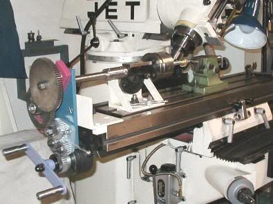
A bracket was built and several gears machined that will remain a permanent part of the fixture. Note that I even installed reversing gears, just like on a lathe, so it will machine both right and left hand helix. Then change gears are needed in order to get the proper ratios, and I just used the gears from an old antique lathe in my collection. It took an extra pair of reduction gears more than used on a lathe, but that was worked in too. When it was all put together the counterbalance knob on the regular mill handle hit the gears so I had to make a new different shaped handle.
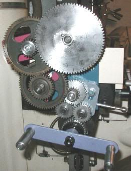
To figure the ratio, you need to determine how far the mill table would have to travel for the work piece to rotate one revolution. Then divide the the table screw pitch (mine is .200") into that, and that is your ratio. Simple as that, well almost. The gear I was machining was specified as 1" pitch diameter, therefore the long travel at 45 degrees would be equal to one times pi. Now pi is not a very nice number to try and factor into a nice ratio. I had several choices. I could machine a couple more change gears of the desired ratio for a one time use. I could change the helix angle slightly so the long travel would come out to a nice even number, or I could change the pitch diameter to make the long travel come out even. I chose the latter, as it only required changing the pitch diameter by a few thousandths of an inch. (I cannot remember for sure, but it was about .015") The housing holding the gears had not been made and so when I got to that part it was only a matter of spacing the center distance of the gears a few thousandths different than what the drawing specified.
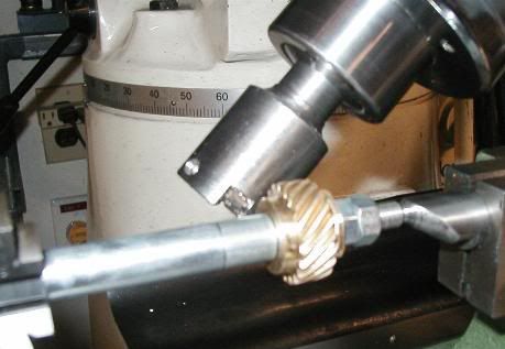
The mill head was tilted to get the cutter in the same plane as the helix. I used a hand ground one tooth cutter for this job. The big work holding spindle drive gear had a multiple number of teeth of the blank I was working on. One grove was cut, Then the gear train carefully loosened and the big gear turned the proper number of teeth and re-engaged, and the next grove cut, and so on.
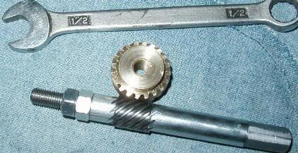
The last picture shows the gears after I finished cutting all the teeth. The gears were installed in the gun and it functions beautifully.
Now I have the means to pursue one of those little side shaft engines that I have wished for, for so many years.
Give it a try, you might surprise the heck out of yourself what you can do.
Birk
If you think about it, a helical gear is a short section of a vary course pitch screw with multiple leads; as many leads, as teeth in the gear. Theoretically you could machine a helical gear in a lathe, but actual practice and theory do not always coincide. However if you set up a work holding spindle on the mill table, that represents the lathe spindle, and gear it to the table traversing screw, that represents the lathe lead screw, the theory works great. By the way I did not invent this idea, I just adapted what others had already done to my own mill.
A bracket was built and several gears machined that will remain a permanent part of the fixture. Note that I even installed reversing gears, just like on a lathe, so it will machine both right and left hand helix. Then change gears are needed in order to get the proper ratios, and I just used the gears from an old antique lathe in my collection. It took an extra pair of reduction gears more than used on a lathe, but that was worked in too. When it was all put together the counterbalance knob on the regular mill handle hit the gears so I had to make a new different shaped handle.
To figure the ratio, you need to determine how far the mill table would have to travel for the work piece to rotate one revolution. Then divide the the table screw pitch (mine is .200") into that, and that is your ratio. Simple as that, well almost. The gear I was machining was specified as 1" pitch diameter, therefore the long travel at 45 degrees would be equal to one times pi. Now pi is not a very nice number to try and factor into a nice ratio. I had several choices. I could machine a couple more change gears of the desired ratio for a one time use. I could change the helix angle slightly so the long travel would come out to a nice even number, or I could change the pitch diameter to make the long travel come out even. I chose the latter, as it only required changing the pitch diameter by a few thousandths of an inch. (I cannot remember for sure, but it was about .015") The housing holding the gears had not been made and so when I got to that part it was only a matter of spacing the center distance of the gears a few thousandths different than what the drawing specified.
The mill head was tilted to get the cutter in the same plane as the helix. I used a hand ground one tooth cutter for this job. The big work holding spindle drive gear had a multiple number of teeth of the blank I was working on. One grove was cut, Then the gear train carefully loosened and the big gear turned the proper number of teeth and re-engaged, and the next grove cut, and so on.
The last picture shows the gears after I finished cutting all the teeth. The gears were installed in the gun and it functions beautifully.
Now I have the means to pursue one of those little side shaft engines that I have wished for, for so many years.
Give it a try, you might surprise the heck out of yourself what you can do.
Birk
