Machine to put cyclical load on steam engine

Home Model Engine Machinist Forum

Help Support Home Model Engine Machinist Forum:

This site may earn a commission from merchant affiliate links, including eBay, Amazon, and others.

Brian Rupnow

Design Engineer
Project of the Month Winner
Joined
May 23, 2008
Messages
14,996
Reaction score
8,293
Location
Barrie, Ontario, Canada
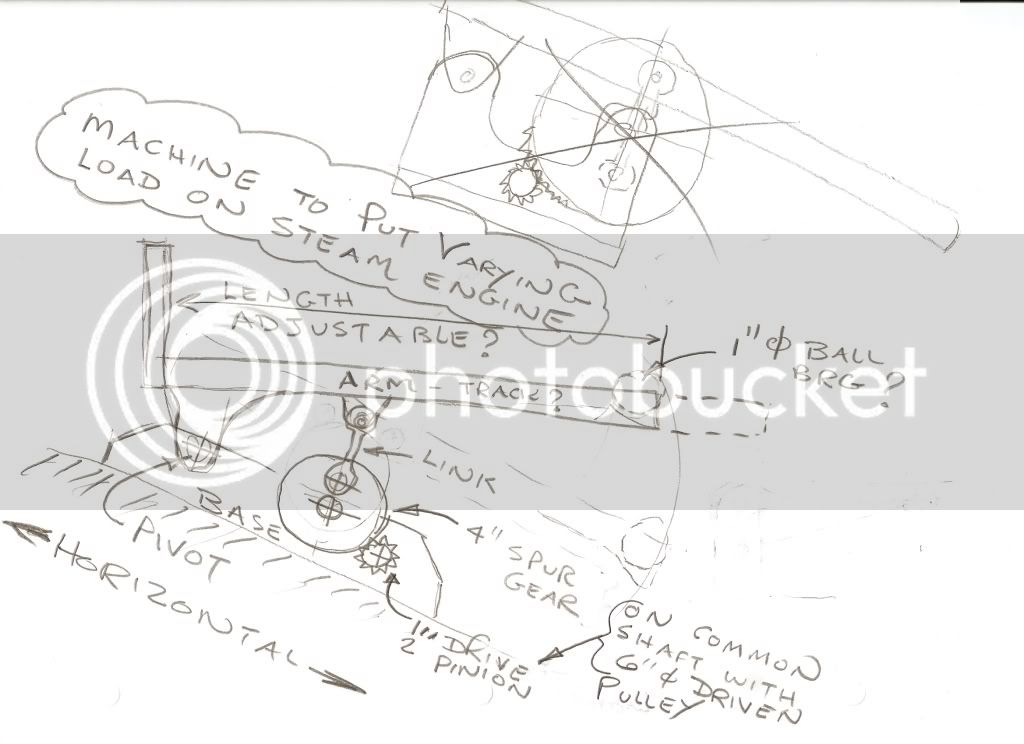
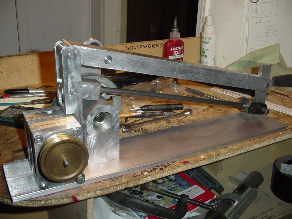
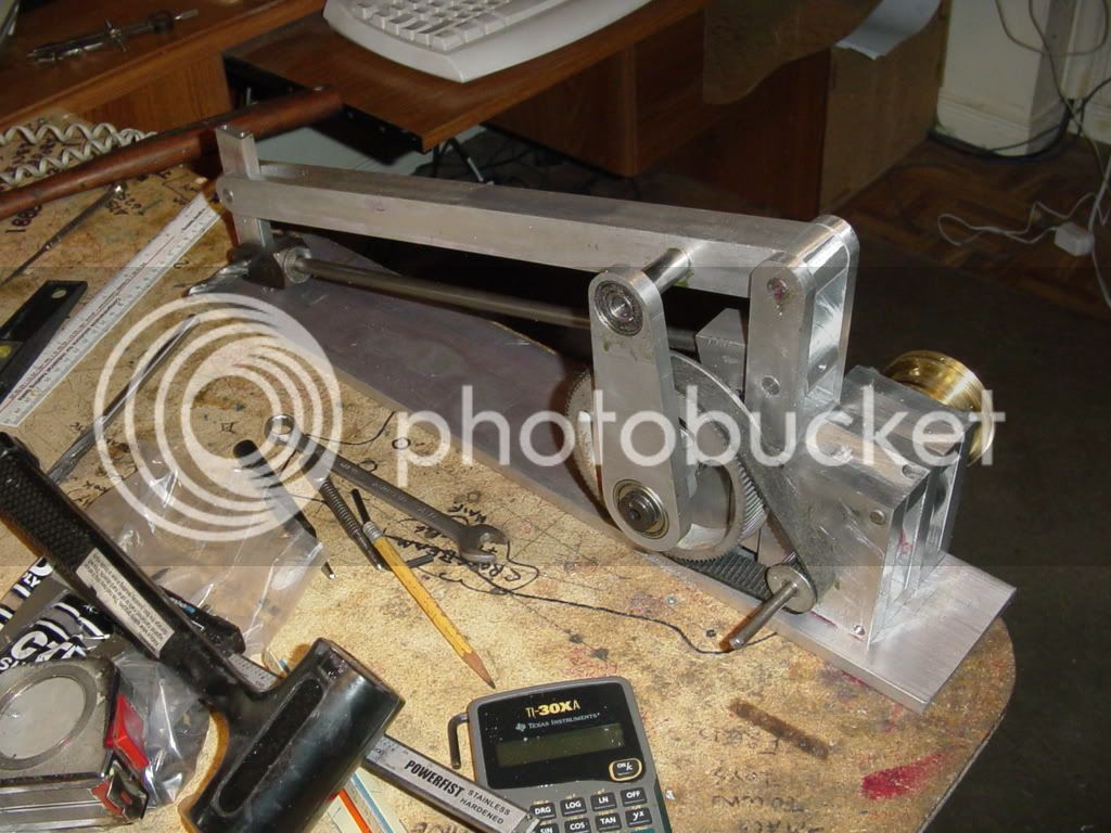
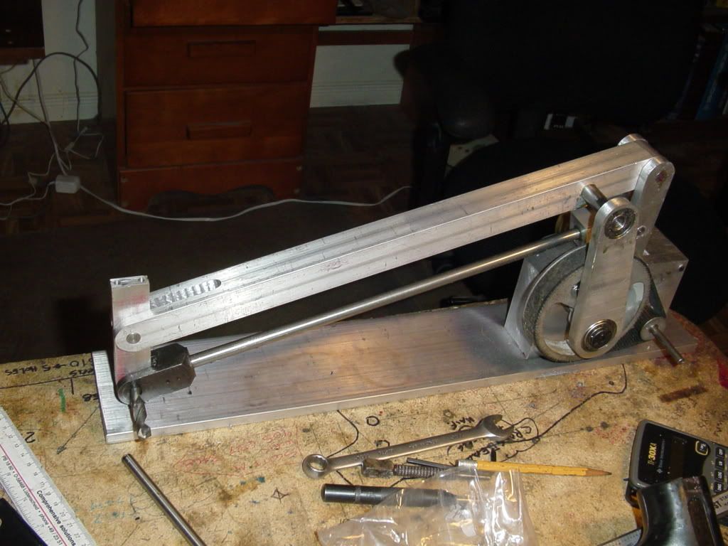
I had originally started this thread in another place, when it was still at the "imagineering" stage, but I have since moved into 'Build it" mode, so have moved over to "A work in progress". What does this machine do, and why did I build it? Well, I wanted my twin horizontal engine with the flyball governor to drive something, which would present a high load on the engine, then a low load, and do it repeatedly, without human intervention, to demonstrate how the governor responds to loads. I plan on exhibiting this machine at steam fairs in my area this coming summer. I have had many good suggestions from folks here on the forum, but most of them involved me doing something to the "device" to vary the load. Since I wanted the machine to do this totally on its own, I designed the following machine. One of the key things that I found is that governors don't respond terribly well to rapidly varying loads, but respond very well to loads that increase and decrease gradually. That is why I have such a massive gear reduction on this device.---Not to increase the torque, but to slow things down so that the load builds and falls in a slow manner. There is a thread currently on the go about planning a project. My projects generally start with a rough sketch, which helps me figure out "How" to achieve a desired result. The attached sketch is my "Rough Sketch".
scan0001-1.jpg
 
Once I have worked the idea out in my head, and spent a fair amount of time working with the rough sketch, I then move to my CAD station and make a model of the machine. When these 3D models are created, all of the math data is ued to create models of the individual components. I control this math data, so I base my models on readily available material sizes, and sizes which I know I am capable of making on my lathe and mill.
assyofvaryingloadmachine-model-1.jpg
 
One of the magical things about good 3D software is that it lets you actually "Run" the machine in realtime, so that you can be sure the result you get is what you are after. you will see that this short animation was created before I had the idea to add the parallel link to the load arm. Although this video clip is very short, I can make it play in a "loop" on my monitor, and view it from any angle as it runs.
 
Of course, once the 3D model is created, it will also create 2D drawings for you automatically---It will create a drawing of the assembled machine.
assyofvaryingloadmachine-2.jpg
 
And of course, it will automatically create detail drawings of the individual components. This is not a fully automated process. It creates all the drawing views that I ask it to, however I have to instuct it where to put the dimensions and I have to compose and type in any notes that I want on the drawing. I don't have to figure out any of the dimensions---That was all taken care of when I created the models, by inputing the correct math data to build them. All I have to do is tell the software where I want a specific dimension---and it will put that math data value in the dimension.
pivottower.jpg
 
I have not included any "Step by Step" pictures in this thread, as doing so would only be repeating other posts I have done while building my steam engines, etcetera. Instead, we will move directly to pictures of an "almost finished" project.
VARYINGLOADMACHINEALMOSTFINISHED001.jpg

VARYINGLOADMACHINEALMOSTFINISHED002.jpg

VARYINGLOADMACHINEALMOSTFINISHED003.jpg
 
Brian.
Nice Brian, very NICE.( as allways)
Happy New Year
fest10.gif

Regards CS
 
Happy New Year Crankshafter. I have the machine setting on the end of my desk right now running, and it works exactly as I had hoped!!! I have to make a platform to put on the end of the arm, and I think I need a slightly larger pulley than the brass one in the photographs. The machine functions beuatifully, and there is a very visible difference in the governor between the load and non load cycles. You can hear a difference in the sound the engine makes when it enters the load cycle and the governor opens the throttle, then you can hear a noticeable change in the sound of the engine when the load comes off and the governor closes the throttle again. I will post a video sometime tomorrow.---Brian
 
Brian,

That's one nifty bit of machinery, (the CAD's pretty fantastic too) :bow:

Best Regards
Bob
 
Brian Rupnow said:
Happy New Year Crankshafter. I have the machine setting on the end of my desk right now running, and it works exactly as I had hoped!!! I have to make a platform to put on the end of the arm, and I think I need a slightly larger pulley than the brass one in the photographs. The machine functions beuatifully, and there is a very visible difference in the governor between the load and non load cycles. You can hear a difference in the sound the engine makes when it enters the load cycle and the governor opens the throttle, then you can hear a noticeable change in the sound of the engine when the load comes off and the governor closes the throttle again. I will post a video sometime tomorrow.---Brian
Looking forward to see the video.
To day I'm doing the valve-timing on my Upshure Twin. But it's so cold in the shop that I'm having a brake now and go to town and meet some fiends and have a hot cup of coffee.
Regards CS
 
How much weight do you put on the load end of the beam Brian? I'm envisioning something like a 5lb house brick to really get things pumping, but perhaps you are using less? I really like that parallel motion to the arm - very nice touch!
 
Tel---I'm still experimenting with that. Last night, with the 2.5" diameter brass pulley that shows up in the pictures, the engine was just busting its butt to lift the beam by itself. Then after it ran for half an hour, and the new mechanism loosened up some, it was lifting the weight of the arm without too much problem. This morning I am making a 3.5" diameter x 1/4" thick platform to put on the end of he arm, like the drawing shows. This will add even more weight out at the end of the arm. I am also making a new 3.5" diameter pulley to replace the 2.5" diameter brass one, so the engine will have more mechanical advantage. I will keep you posted as this develops.---Brian
 
I've been following this thread for a while now. I found something while reading that may be of interest to anyone thinking about throttles and where to implement them. I hope this is helpful to someone

untitled.gif


Kermit

 
Unfortunatley air doesn't expand as much as steam so the variable cut off method won't work to good with air.

My opinion, but your milage may very. :big:

Bernd

 
Bernd said:
Unfortunatley air doesn't expand as much as air so the variable cut off method won't work to good with air.

My opinion, your milage may very. :big:

Bernd

Bernd--I think perhaps you need to proof read that!!!
 
Brian

I have really enjoyed following this project. From engine to governor to gear box to cyclic load, neat progression. Where can you go from here?

Now that you have invested in a tach, maybe you can test and report the speed fluctuation for the load/no load cycle both ways. With and without the governor and starting with the same no load speed. If I understand the function of a governor, it should keep the engine speed under load at a higher percentage of the no-load speed than if there were no governor.

A little engineering data if you please. maestro.

Jerry
 
Captain Jerry--As close as I am able to tell, when the governor is operational, the maximum "load speed" of the engine is 359 RPM, and the maximum "No-Load" RPM, when the arm is falling, is 400 RPM. When I remove the o-ring drive which powers the governor, the maximum "load speed" when the arm is rising is 415 RPM and the naximum "No load" speed with the arm falling is 540 RPM. If I take the difference in RPM with the governor on, (41 RPM) as a percentage of the average speed (359 + 400/2=379.5) then 41/379.5 x 100=10.8%
If I take the same calculation with no governor, the net difference is 125RPM. ----400+540/2=470---so--125/470 x 100=26.5%
If I have made this calculation correctly, then the speed is controled by the governor, it is held to about 2.5 times closer to the average speed than without a govenor in place.
 

Latest posts

Back
Top