Lobo Pup Twin 1.6 cc diesel

Home Model Engine Machinist Forum

Help Support Home Model Engine Machinist Forum:

This site may earn a commission from merchant affiliate links, including eBay, Amazon, and others.
Gail...

Are ya sure I can't send you a bunch of this snow??

I've not given up on your thread. I just love little aero engines and diesels!!

Once it warms up a hair I'm sure you'll work the kinks out of that little Wolf....
 
Zee, I know you never give up on anything. Thanks for staying with me.

Mike, I grew up in Alaska. Winter time is for building. Summer time is for playing outside. My weather here in NM suits me just fine. Snow a few times a year is plenty.

The last 10 days have been busy. Santa was good to me and I hope he was good to you also. He brought me a new (to me) Dumore model 14, Tom Thumb, tool post grinder. It is about 40, maybe 50, years old, but except for a rotted with age power cord it is in like new condition. Age is OK because that is about how long I have been wanting one. I have been trying to use a hand held rotary tool on a mount, but it was not rigid enough for deep cylinders. He managed to get it here on the 23d, so I was able to have it running on Christmas day. Made a mount so it fits on my QCTP and some new arbors that will reach down into 3/8 inch bore cylinders. A few tests on Christmas day shows that it will work well in the future, and I already have plans for the first application.

Now back to the Pup.
I only had one good day for running. The engine was complete with both cylinders. It ran OK, but was still a little touchy on the needle valve setting, and a revised venturi did not help. So it was back to check the drawings.

The problem appears to be that I miscalculated the primary compression at the very beginning of the design. Primary compression is the crankcase compression that is used to induct the fuel mixture and to transfer the mixture to the cylinder. Don't know what I did, but it was way low. That meant that the air velocity in the venturi tube was too low for good fuel draw.

Since there were a number of other little changes from the original concept, a complete redraw was done. The new drawings have replaced the old drawings attached to posts #1 and #2 and are annotated in Post #3 of this thread. I plan to build a Version 2 engine over the next month or so. Version 1 is going into the display case as is. Version 2 will not have much of a photo story going with it as most of the operations are the same as the original, although dimensions will vary some.

Primary differences from Version 1 to Version 2 are:
1. Crankcase and overall height reduced by 5/32 inch.
2. Connecting rod shortened.
3. All ball bearings replaced by bronze sleeve bearings.

I left the cylinder and piston the same. This changed the timing by less than 2 degrees. Since the original timing was more of an educated guess anyway this should not impact the running enough to measure.

If the eyes and fingers hold out the target date for next run will be Valentines day, or groundhog day if things go exceptionally well. Construction should go fairly fast as it takes me twice as long to shoot photos and write about things as to build them.

Gail in NM
 
Gail,
You had me scared for a while. The long post and the tile to the left.... Lobo Pup twin 1.6cc dies.

I read the title fast and didn't see the .... after dies. Glad to see your still at it!

Tony
 
OK. Time to get started on the Lobo Pup Twin Version 2.
I had planned to start on New Years Day, but I could not think of anything I would rather do on New Years eve than start on a new engine. So I sawed up a chunk of 6061 aluminum to make the crankcase. Squared up 4 sides and then did the ends using a squaring stop on the vice. Measured. The ends were not square and now the length was too short on two sides. Removed the squaring stop and removed the errant chip that was under it. Back to the saw. Must have been cross eyed as the second piece was was all ready too short with out any machining. The third piece was a charm and by the time the new year arrived local time I had a piece that was square and to dimension.

Operations were the same as on version 1, but with a few different dimensions as version 2 is 5/32 (0.156) shorter. One additional feature was to add cutouts on the mounting lugs. Because the venturi is located closer to the mounting lugs, the cutout makes it easier to get the fuel line on and not to have too sharp a bend as it heads off to the fuel tank.

Photos show the crankcase finished up with the rough sanding done to remove most of the machining marks. A little more sanding with finer grits and then polishing still needs to be done. I will reserve those operations until there a TV show or movie I want to watch, or at least listen to. That is when I most often do my hand work. I won't machine with the TV on for safety reasons. I am too easily distracted.

Gail in NM

Crankcase1.jpg
Crankcase2.jpg

 
I won't machine with the TV on for safety reasons. I am too easily distracted.

Good onya, Gail. I've been blowing that horn for a long time but in our sports-drugged culture it seems to fall on deaf ears. I can't think of anything that has more potential to cause an accident than a blaring TV when you're running a machine. My pal, three-finger Joe, agrees with me too.
 
Well, the Lobo Mk II is looking good! :bow: I hope you'll post photos of the new completed parts.
 
Marv,
The older I get the more easily distracted I have become. Besides the more or less universal CRS syndrome, I also find that I think a lot more about the hereafter. I walk out to the shed to get something and when I get there I find myself saying "What am I here after". But seriously, I find that the more distractions I eliminate the more productive I am as well as being safer.

Vernon,
Never fear. I plan to post photos of all completed parts as I finish them. I just will not be posting in process photos of things that are the same as have been posted in the Version 1 portion of the thread. Things that are new or different I will post in process photos of.

Gail in NM
 
The connecting rods are different in that they are shorter and a little bit narrower. The same methods were used to make them as used in version 1. Although the cross section of the rod is smaller, they are still plenty large. Compression ignition engines are hard on rods, so I always make sure they are are on the large side.
Gail in NM

Conrod1.jpg
 
Nice work Gail,

Shame about the first one but can't wait to watch Mk 2 materialise now!

Nick
 
Thanks Nick,
Nothing to worry about on the Mk1 version. I consider it a success. It runs and has reasonable power. Just not quite as stable as I would like. I learned enough from it to make a better one is all. The Mk2 just has all the chnages in it that should make me happy and the engine suitable for others to build if someone desired. Most notable is the getting rid of special parts (hard to get) like the ball bearings that I used. The rest of the changes just improve things in areas a little at a time and should improve running qualities.
Gail in NM
 
Good going Gail!

And thank you; as this engine is definitely on my future build list, I really appreciate the fact that you are aiming at easier-to-get parts.

Kind regards, Arnold
 
Gail,
Was there a reason for going with a shorter rod?
 
Kevin,
The shorter rod reduces the dead volume in the crankcase by lowering the piston. This increased the compression ratio in the crankcase, which is the primary compression. The higher primary compression will increase the air intake velocity and the transfer velocity. That should make the needle valve less sensitive to RPM variations and fuel level.

I was going to get some more progress posted, but found another area that would make building easier. Just changing the drawings now, so should be able to post them later tonight. These changes will not change performance.

Gail in NM

 
Thanks Gail. That all makes sense now.
Are you also going to shorten up the cylinders or use a longer piston?
 
I took 0.156 off the top of the crankcase and dropped the intake and exhaust ports in the crankcase down. This let me keep the piston and cylinders the same, and reduced the overall height of the engine.
Gail in NM
 
Just a quick update with no photos.

I turned up the front bearing mount and the center bearing mount and the bronze bearing to go in them. Also the rear crankcase cover.

Then I test fitted them to the crankcase. What is going on?? The front an rear parts hung down over the bottom edge of the crankcase. I don't know how, but I located the bore for the crankshaft 0.015 low. Of course the dozen 0-80 holes moved with it perfectly. I thought about how hard it would be to compensate for it. Gave up and decided it would be less work to make a new crankcase. Between Tony's "setup" crankcases on his Whittle V8 andm my "extras" on the MK2 we are getting a good collection going. This is start #4 for the Lobo MK2. Fortunately on mine the first two were screwed up early when getting a blank squared up.

Now the #4 crankcase is about 75 percent done. All the critical work is done and double checked. I am just starting to start profiling the outside so should be done machining tomorrow and ready for polish.

Gail in NM
 
Thanks for the update on the Lobo, Gail. You're a trooper, and like Tony, a good example for us!

Dean
 
Thanks Dean.
Tony and I are just persistent is all. I think that is a trait that all model engineers have. Zee is one of the best examples on this site.
Gail in NM
 
If you have followed this thread from the early days you know that I rounded the bottom of the crankcase using a CNC mill. Outside of the forum some one asked me how to do it with out using CNC. Since I screwed up the last crankcase and was making a new one I decided to take the little bit of extra time to illustrate how I do it without CNC. There are a lot of other methods, but this works for me and I have used it, or a variation, in the past. One other way that is widely used is to mount the crankcase on a mandrel in a dividing head, indexer, or spindex.

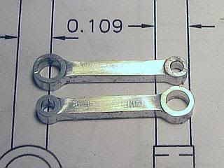
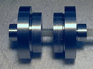
My method uses a variant of filing buttons. Two buttons are made. The outside of both are the same, and the hole through one is a clearance hold and the other has a tapped hole. One end is made to fit the inside of the crankcase bore, 0.718 in this case. The center section is made to match the desired radius of the outside of the crankcase, 0.469 radius or 0.938 diameter for the Lobo. The other end is small diameter. It must be large enough that the bolt head does not protrude, but small enough that the remaining portion can be clamped securely in the vice. I made these 0.312 diameter. This was the same as the 8-32 bolt head that I was going to use, so I had to turn down the bolt head some. The only reason for using 8-32 was that it was the only bolt I had that was long enough.

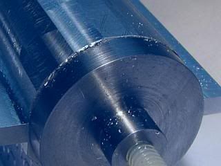
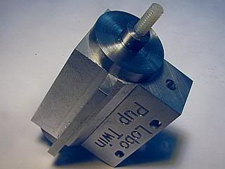
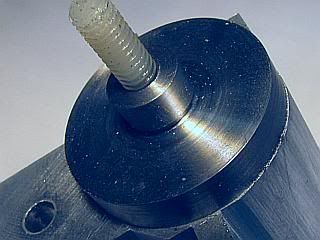
The first photo shows the two buttons on a bolt. Notice that a relief is cut at the junction between each diameter so any radius on the lathe tool does not interfere with the buttons seating. Barely visible in the photo is a generous countersink on the left hand button, which is the threaded one, to make it easy to start the bolt. The second photo shows the buttons mounted on the crankcase.

CCFix1.jpg
CCFix2.jpg


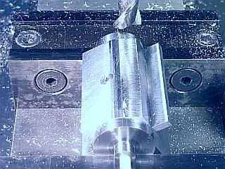
The assembly is clamped in the milling vice with the small diameter of the buttons resting on the vice jaws and clamping on the large diameter. You may want to check that the vice jaws are at the same height before doing this. The cutter is set to just clear the filing button and a milling cut is made with an end mill. There will be no need to change this cutter height on the rest of the passes. Turn the spindle off and rotate the part a few degrees, keeping the buttons pressed down against the vice jaws, and then make another cut after clamping. Repeat until the crankcase bottom is a series of flats. The closer the flats are to each other the less filing will have to be done. The only precaution is to make sure the cutter does not touch the crankcase mounting lugs.

CCFix3.jpg
CCFix4.jpg


After the entire bottom is done, finish with a file, filing end to end, until the file just touches the buttons on each end. If you only made a few cuts with the mill, it will take a lot of filing, but if you make a lot of cuts with the mill it will only take a few minutes to file. No photo of the filing is shown. Just the finished crankcase polished and ready to go.
Gail in NM

CCFix5.jpg
CCFix6.jpg


Latest posts

Back
Top