Lobo Pup Twin 1.6 cc diesel

Home Model Engine Machinist Forum

Help Support Home Model Engine Machinist Forum:

This site may earn a commission from merchant affiliate links, including eBay, Amazon, and others.

GailInNM

Administrator
Staff member
Administrator
Global Moderator
Joined
Feb 17, 2008
Messages
2,326
Reaction score
440
NOTICE: A COMPLETE REDRAW WAS DONE WITH MANY CHANGES MADE ON 12/30/09. ALL THE DRAWINGS IN POSTS 1 & 2 HAVE BEEN UPGRADED TO THIS VERSION 2. CONSTRUCTION OF PARTS THAT HAVE MAJOR CHANGES IN THEM BEGINS AT POST #162 AS WELL AS ALL DIALOG REGARDS VERSION 2.


With the PMC IMP project complete I started sketching on a new engine. This one is an original design and all drawings for Lobo Pup Twin will be published in this thread. This will simplify the Work In Progress descriptions as I had to use a lot of text on the IMP project as the drawings were not available for free download. The drawings will be attached as PDF documents on the first three posts of this thread. It takes three posts because of the attachment limitations of this site.

Since this engine has not been built, there will be revisions to the drawings as the build progresses. A record of these changes will be documented in these first three posts as the drawings are updated. The initial release of each drawing will have a REV of --, and later revisions will be A,B......

There are sure to be revisions. I am not a great draftsman, so I know there will be omissions and errors. I have done enough drawings and engine designs that I do not expect that there will be a lot of these. I expect the engine to run as I have not had one of my engine designs that did not run, at least not in the last 15 years or so. Some did take a bit of tinkering however.

After the build is complete, the drawings will be available in DWG or DXF format for anyone who might be interested in using them in CAD to modify for their own purposes.

The drawings carry a copyright notice with the copyright released to the public domain for non-commercial purposes. This means that you can copy, modify, distribute or publish as long as there is no charge or profit from doing so. The only purpose for this copyright is to discourage people from selling copies of them.

Because many of the techniques used for construction as the same or similar to those used on the PMC IMP I will probably make reference to the posts there. This just because I am lazy and would rather build than type. The link to the main thread is:
http://www.homemodelenginemachinist.com/index.php?topic=4422.0
but if I make reference to anything I will provide a direct link to the post involved.

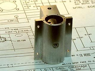
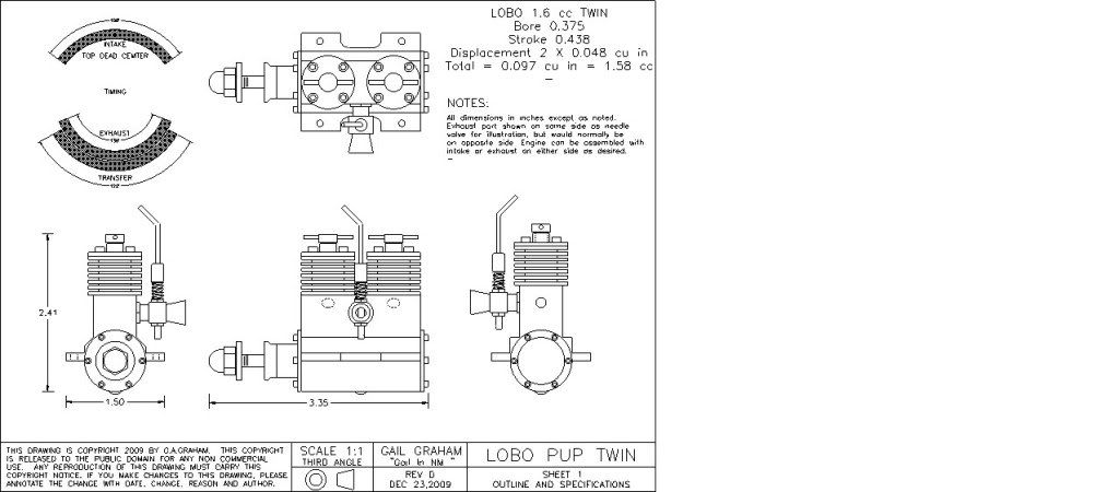
The general specification can be seen in the following photo. It is the same as Page1.pdf that is attached.
Pages 1 to 4 are attached to this post. Pages 5 to 8 are attached to the next post.

Gail in NM

PAGE1D.jpg


View attachment Sheet1E.pdf

View attachment Sheet2E.pdf

View attachment Sheet3E.pdf

View attachment Sheet4E.pdf
 
The general design considerations were to make a fairly low tech twin of fairly small displacement. The design would be considered fairly conventional - if we still lived in 1955. The stroke/bore ratio is 1.17, a little long by todays standards, and a little short for 1955. A 3 piece crankshaft is used to avoid having split big ends on the connecting rods. The center two crankshafts are permanently assembled to form one crankshaft which carries both crank pins. The front crankshaft is driven by engagement with an extended front crankpin. Both crankshafts are running in sealed ball bearing races. The bearings each have two Teflon seals. This is done to isolate the primary compression space of the two cylinders and to seal the front primary compression space from the outside world. Teflon seals were chosen as I did not know how rubber seals would react to the ether in it fuel. They are also a standard bearing in the radio control car world and are readily available at low cost.

There would be nothing wrong with running both the center and front crankshafts in plain bearings by removing the bearing cavities in the center bearing housing and the front bearing housing. If the crankshafts are well polished, they would be fine in 6061-T6 aluminum.

The timing is fairly conservative so this is not going to be a high speed engine. Top RPM is expected to be in the 10,000 range. As with all side port designs with the crankshaft on the cylinder centerline, there is no favored direction for the engine to run.

The crankcase is can be switched front to back at assembly so the exhaust and intake can be reversed. This opens up another possibility of extending the rear crankpin so it is the same as the front crankpin and replacing the rear cover with a second front crankshaft and front bearing assembly. Then the engine would be double ended. Direct drive tether car racing anyone?

Gail in NM
 
-
Plan Revision Status
12/30/2009 Complete redraw. All drawings updated to REV D, which is Version 2 of the Lobo Pup Twin.
Version 2 begins at post #162.
01/05/2010 O-Rings added to Front Bearing Housing and Rear Cover to eliminate gaskets.
Sheets 4,7 & 8 changed to reflect this but Drawings left as REV D
2/09/2010 All drawings updated to REV E dated 2/09/2010. These drawings are the final set for the Mk2 version
and reflect the "as built" of the Lobo Pup Twin MK2.

View attachment Sheet5E.pdf

View attachment Sheet6E.pdf

View attachment Sheet7E.pdf

View attachment Sheet8E.pdf
 
I think the drawing package is complete. Probably wrong in places, but complete. All the drawings are contained as PDF attachments in posts 1 and 2. Since the first release on 9/24, a general arrangement drawing has been added and a copule more small parts added to page 7. For you CAD experts, please don't laugh too hard. Snickering is OK, but no LOL.

Whats in a Name?
For those not living in the Southwest USA, the Lobo may not be a familiar name. The Lobo is the Spanish name for wolf, and in particular refers to the Mexican Grey Wolf. The Lobo has many of the same traits as model engine builders. It is a solitary animal, seldom seen with others of it's kind except during mating season, or in our case the occasional model engineering show. It is an endangered species, but with it's reintroduction to the wild it is making a little bit of a comeback, although less than 100 exist in the wild.

As related to my hopes for this engine, the Lobo is known for being a steady runner. Not the fastest, but very steady.

As related to me. When things go wrong in the shop, I go out the top of the sand dune that I call a back yard and howl at the moon when it is up, the stars when it is not, and otherwise just for the fun of it. Unlike the Lobo I almost always have a companion when I do my howling, my 3 year old Papillon shop dog who looks nothing like a Lobo, but does enjoy the howling with me.

With all the preliminaries out of the way, it is time to start making chips. First up will be the crankcase. I will start it either this evening or in the morning as personal matters are going to eat up most of the rest of today. Then it will be my time to howl.
Gail in NM

Wolf_Howling.png


Really looking forward to this combined design/build Gail - Thank you for your effort :bow:

Regards, Arnold

 
With the planned personal items out of the way plus two family emergencies (two adult offspring, two emergencies) I finally got started on the crankcase.

Sawed off a piece of 1-3/4 square 6061 extrusion and then squared it up and face milled it to the major dimension of the crankcase.

Crankcase1.jpg
Crankcase2.jpg


After making a rough sketch of the holes on the crankcase, I center drilled, drilled and tapped the 12 0-80 holes and the 8 2-56 holes. The rough sketch is so I would not put the 0-80 hole pattern on the top edge on one end and the bottom edge on the other end. I like to get all the tapping out of the way as early as possible as a broken tap is a difficult to repair error and very irritating if it occurs after a lot of machining is done. It can become a real possibility if you are not used to doing 0-80 holes. I also put a center hole in location for each cylinder and on both ends of the crankshaft bore for setup purposes for boring those holes. All holes were drilled using the DRO on the mill for location.

Crankcase3.jpg
Crankcase4.jpg


Off to the lathe to bore the hole for the crankshaft assemblies. The blank was set up in the 4-jaw chuck using a wiggleer and a dial indicator to indicate the center of the hole to be bored. Notice the strips of soft aluminum under the jaws to protect the surface of the part. The bore was rough drilled with a 1/2 inch drill which is the largest I have.

Crankcase5.jpg
Crankcase6.jpg


The hole opened up the a short stiff boring bar that would just fit in the 1/2 inch hole and the part is now ready to go back to the mill where I will put the 0.118 hole in the bottom and bore the cylinder mounting holes with a boring head. The crankshaft bore was done first because I did not want any holes into that bore that might distort that bore by having an interrupted cut.

Crankcase7.jpg
Crankcase8.jpg


Gail in NM
 
Drawing changes:
Page7A replaced Page7 on 8/27/09 with added parts
Page5A replaced Pace5 on 8/30/09 With missing dimensions added and correction to drawing on intake port.

Gail in NM
 
Time to do more holes in the crankcase . I started with the holes for the cylinders.

I moved the crankcase from the lathe to the mill. Started by drilling the holes 31/32, which is 1/32 under teh finished hole size. I had my boring head still set up for 1/2 inch hole from the last time I used it, so I bored the holes to 1/2 inch diameter using it. If it had not been set up, I probably would have reamed the holes.

Crankcase9.jpg
Crankcase10.jpg


Flipped the crankcase on end and center drilled, drilled and reamed the 0.156 for the fuel distribution passage. The only reason I reamed the hole is that my reamer leaves less of a burr on exit than a drill bit does, so there will be less to deburr in the 1/2 inch holes when I get to that step.

Crankcase11.jpg


Then on to the clearance hole in the bottom for a 4-40 screw and the counter bore of the hole so the screw will set flat. Counter bore depth is not critical. Calculates out to be about 0.018 deep with a 1/4 inch end mill, so I cut it 0.020 deep. The edge can get blended when the bottom of the crankcase is shaped to a half round.

Crankcase12.jpg
Crankcase13.jpg


Gail in NM
 
All the holes in the crankcase that can be reached have been bored, drilled and tapped as required. Now it is time to start shaping the outside of the crankcase.

First up is to get rid of the bulk of the extra metal. A 1/2 inch endmill is used to rough out the profile.
An 1/8 inch endmill is used to cut the exhaust openings.

Crankcase14.jpg
Crankcase15.jpg


The venturi mount hole is center drilled, drilled through to the 1/2 inch bore with 0.156, and opened up to 0.228 to almost full depth. Then the hole is tapped 1/4-40. I got about 5 full threads.

Crankcase16.jpg
Crankcase17.jpg


I had drawn a step between the mounting lugs and the cylinder block part of the crankcase. It appears on all the initial release drawings. I knew it didn't look good when I was drawing it, but now that it is committed to metal it really looked ugly. I had thought about several ways to blend it using a ball end mill, but wanted something that would not take a special tool in case someone else wanted to build a copy of this engine at a later date. So I decided to just use a simple 45 degree bevel. I put the crankcase in a vee block to hold it at 45 degrees and then milled away the offending bit of metal with a 1/4 inch endmill. I positioned it all by eye for the first side and then flipped the crankcase over and did the other side.

Crankcase18.jpg
Crankcase19.jpg


Gail in NM


Gail this is going to be a good one to watch, thanks for posting. I haven't messed with any RC engines for a long time now....maybe someday I will have the time to get back into it. Your plans are easy to read, the only thing I noticed was a misplace hole in the one your your circular patterns (it's sitting outside of the part).

I am looking forward to seeing this one run!!,

PS page 7a for the gasket
 
Thanks Bob.
I found the hole you were referring to and corrected it on the master.

I have several minor corrections on the masters and when I collect enough of them I will update the PDF's. All the corrections to date have been minor, so would not cause any one a problem if they are following along on the drawings.

When it is done I will repost all the drawings "as built"
Gail in NM
 
Your welcome and good job, I know it's not an easy task to create drawings when you know others will probably be building from them. This at least is true for those of us on the board that are just now getting to do them. I took 4 years of drafting in high school but the lessons are pretty much long gone. They are starting to come back a bit as I do a few more drawings. I kept finding missing dimensions as I went along and then when I built a second one from my own plans I found the rest of the missing dimensions....Maybe someday..:)
 
Nice Gail,
Man you work fast! Interesting build
Tony
 
Bob,
I learned a long time ago that I was not a good draftsman. For the last 20 years of my working life I had a several very good design draftsmen, one at a time, working for me who could clean up my rough drawings. That included everything from things on napkins from the pub to mostly ACAD sketches that were to scale, but frequently had only a few dimensions on them for reference purposes. They saved my butt more often than not.

Tony,
Thanks for the interest.
As far as working fast, it helps a lot when you have spent the previous two weeks drawing the parts. When I design, I am always thinking about how I am going to make the part, and I design the part to suit the tools and tooling that I have. Where possible I try to design so others can build also with a minimum amount of tooling required. So, when I start to make a part, I already have all the processes in mind and the dimensions are firmly embedded in my head. I typically work in imperial fractions where ever possible. Suits the tooling I have and makes dimensions easy to remember.

Gail in NM
 
Now back to the crankcase.

I have been using the bottom of the crankcase as a square reference to clamp everything while I did all the other features. Now it is time to get rid of all the extra metal there. I used a CNC mill to round the bottom of the crankcase, but I have rounded crankcases in the past on manual machines by mounting on an arbor and either using the arbor in a Spindex and milling a bunch of flats to be blended with a file or by planning with a wide parting tool held 90 degrees to the normal mounting and racking the carriage on the lathe to plane the section round while rotating the spindle a little at a time. All three methods take about the same amount of time, but with the CNC I can eat lunch while the mill is doing it's thing.

After the bottom is rounded, it is easy to reach the beams to drilll the mounting holes.

Crankcase20.jpg
Crankcase21.jpg


Then on to clean up. There are internal burrs where the cylinder block bores meet the crankcase bore and where the intake passage meets the cylinder bores.

For the inlet passages I just run a drill bit through with my fingers, first from the end and then from the side of the crankcase. Then repeat a couple of times.

For the cylinder block bores and crankcase bore, I use a Flex-hone, not as a hone, but as an abrasive brush or file. I use one that is under size and just work it by hand. A piece of abrasive paper of 400 grit or so wrapped around a wooden dowel will work as well.

I rough cleaned the crankcase at this point, but the plug for the access hole to drill the internal intake passage still needs to be plugged before the final clean up.

At his point the crankcase looks like this.

Crankcase22.jpg
Crankcase23.jpg

Crankcase24.jpg


Great work Gail,

Nicely laid out WIP too.

Thanks for posting.

 
That's coming along great-guns Gail - a very good job :bow:

Thank you, Arnold
 
Gail,

You do beautiful work. :bow:

Best Regards
Bob
 
Gail

Another outstanding thread,
great pics along with the write up and drawings

top notch :bow: :bow:

regards
Andy
 
Kevin, Arnold, Bob and Andy,
Thanks for your kind comments and for following along with me on this journey. It means a lot to know that right or wrong there are people who are interested in what I am doing.

To finish up the crankcase, all that is needed is to plug up the hole in the rear of the crankcase that was used for access to drill the internal intake passage. That plus some work with some abrasive paper later IF I want it to look better.

The plug is just a section of aluminum rod turned to fit the hole with the length so that it does not protrude into the 1/2 inch bore for the cylinder sleeve. Actually it could intrude on the bore a little bit without causing a problem as the sleeve is cut away there for the transfer passage.

With the bit turned, a hole is cut in a piece of thick paper and the paper is marked so the hole in the crankcase is aligned roughly over the hole. The paper is then marked around the crankcase. The paper will act as a spacer so the plug will protrude a little bit from the crankcase when installed. After cleaning both the plug and the hole in the crankcase with solvent so there is no oil on them, a small amount of high strength Loctite is applied to the plug and the plug inserted into the crankcase. Then the crankcase is set on the paper spacer and the plug is pushed from inside the crankcase so it it touching the surface the paper is on. Go do something else for a while as the Loctite cures.

Crankcase25.jpg
Crankcase26.jpg


After the Loctite is cured, the plug will be sticking out of the crankcase a little bit because of the spacer. Clean a file and file the offending bit away so it is flush. I use a 6 inch single cut mill bastard file. The a quick rub on 400 and 800 grit abrasive paper with a little bit of water or oil on it and the plug disappears.

Crankcase27.jpg
Crankcase28.jpg


Gail in NM
 
Back
Top