
You are using an out of date browser. It may not display this or other websites correctly.
You should upgrade or use an alternative browser.
You should upgrade or use an alternative browser.
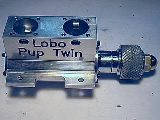
Lobo Pup Twin 1.6 cc diesel
- Thread starter GailInNM
- Start date


Help Support Home Model Engine Machinist Forum:
This site may earn a commission from merchant affiliate
links, including eBay, Amazon, and others.
- Joined
- Feb 17, 2008
- Messages
- 2,326
- Reaction score
- 440
Thanks Dean.
I like this method as it is as quick to machine as using an arbor and takes less material than an arbor. Also it takes a lot less time to set up than using an indexing head and making an arbor.
Another off forum email asked if the Lobo could be made as a glow plug version instead of compression ignition. Fuel for compression ignition is not as easily available as is glow fuel because it is not as popular, at least in the United States. I responded directly to him, but thought others might be interested.
A glow version should be no problem. All the port timing is suitable so no changes would need to be made in the bottom end of the cylinder. The top end of the cylinder would need to be reduced in height to get the glow plug down to the right height because the contra piston would disappear. A standard glow plug is too large in diameter to just recess in a new head. I did a couple of quick calculations, nothing final understand. I appears that to get the compression ratio in to the 6.5:1 area that the cylinder would have to be trimmed about 1/8 inch. This could be accomplished by removing one fin and one fin spacing from the top and by spacing the remaining fins a little closer by thinning the fins down. Glow engines run a little bit hotter than compression ignition engines, but the Lobo has lots of cooling. I can hold on to the cylinder for several seconds before becoming uncomfortable. The crankcase is rather massive and it get rid of a lot of heat also.
Should there be sufficient interest, after the current build is finished I can draw up the changes for a glow ignition engine. I will be ready to move on to something different by that time, so I probably would not build one myself.
Gail in NM
- Joined
- Feb 17, 2008
- Messages
- 2,326
- Reaction score
- 440
With a GOOD crankcase in hand it is time to start filling it up.
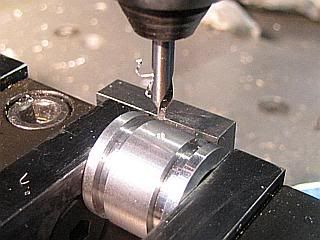
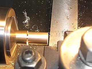
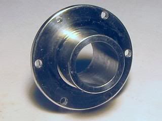
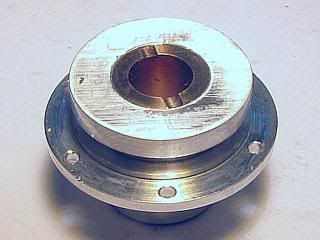
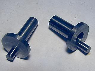
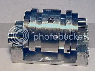
First off is the Center Bearing Housing. It is quite a bit different from the original version. First off two O-rings have been added to make the fit between it and the crankcase less critical. Next the bore is just a reamed hole to take a sleeve bearing instead of recessing each end to take a ball bearing.
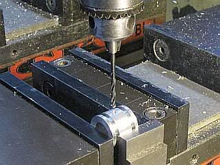
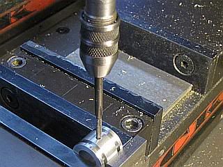
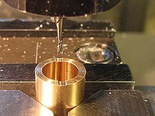
The OD is turned to be a close sliding fit in the crankcase and the O-Ring grooves cut. After cutting off and facing to length it is center drilled, drilled and reamed to take the center bearing. The housing is moved to the mill and drilled and tapped for the 4-40 retaing screw that locates and secures in the crankcase. Run a reamer through the center bore by hand to remove any burrs caused by the tapping operation and also remove any burrs on the OD with abrasive paper. Finally cut the grooves in one end that engage the bearing insertion tool. The grooves should be about 90 degrees from the tapped hole to make alignment easier but the angle only needs to be eyeball precision.
Gail in NM
First off is the Center Bearing Housing. It is quite a bit different from the original version. First off two O-rings have been added to make the fit between it and the crankcase less critical. Next the bore is just a reamed hole to take a sleeve bearing instead of recessing each end to take a ball bearing.
The OD is turned to be a close sliding fit in the crankcase and the O-Ring grooves cut. After cutting off and facing to length it is center drilled, drilled and reamed to take the center bearing. The housing is moved to the mill and drilled and tapped for the 4-40 retaing screw that locates and secures in the crankcase. Run a reamer through the center bore by hand to remove any burrs caused by the tapping operation and also remove any burrs on the OD with abrasive paper. Finally cut the grooves in one end that engage the bearing insertion tool. The grooves should be about 90 degrees from the tapped hole to make alignment easier but the angle only needs to be eyeball precision.
Gail in NM
sourdoughsmitty
Active Member
- Joined
- Dec 27, 2009
- Messages
- 30
- Reaction score
- 0
HI Gail ,
I amm the one who asked about glow use ,I just checked back here to the forum and you answered a ? that I emailed you about r/e cyl change for glow thanx that will help a bit I like the upgrade to bronze bush I too used many a motor with them the only caution to others here is make sure that you use castor for the lube instead of the the usual modern stuff as it seems to keep the bearings better ,just my experience with old motors here
thanx smitty
- Joined
- Feb 17, 2008
- Messages
- 2,326
- Reaction score
- 440
Smitty, your comments about lube are appreciated. The major fuel suppliers have different formulations for ball bearing and sleeve bearing engines. Pay your money and take your choice.
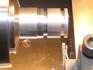
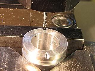
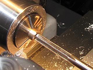
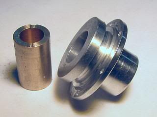
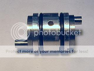
Withe the center bearing housing done the center bearing can be made and fitted to the housing. The bearing is made from SAE660 bronze. Other designations for the same material are CDA932 and C93200. The the OD of the bearing is turned to be a slip fit in the housing. The inside is drilled a reamed to 5/16 (0.3125) and the front half of the center crankshaft will be made to match this bore. The length is 0.010 longer than the housing to prevent the crankshaft webs from touching the housing.
Both ends of the bearing have a shallow groove (0.062 wide X 0.005 deep) cut across them for oil passages to the crankshaft.
Gail in NM
- Joined
- Feb 17, 2008
- Messages
- 2,326
- Reaction score
- 440
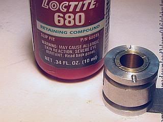
Installing the bearing in the bearing housing is done using any Loctite retaining compound such as 609,640 or 680.
The only tricky part is that the bearing needs to protrude about 0.005 inch from each end of the housing. A spacer with a notch in it is used to space the bearing. Heavy weight printer paper, 30 pound, is about 0.005. Regular copy paper is only about 0.003. Clean the housing bore and the bearing OD with alcohol, acetone or some other solovent that leaves no residue. Apply the Loctite near one end of the bearing and insert in into the housing with a twisting motion. Place the housing over the spacer so the bearing fits in the notch and push the bearing all the way down. By sliding the assembly around on the spacer you can feel the edge of the notch in the spacer so you know that the bearing is in the correct position.
Gail in NM
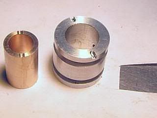
- Joined
- Feb 17, 2008
- Messages
- 2,326
- Reaction score
- 440
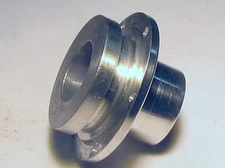
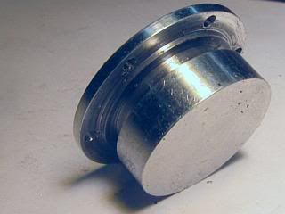
The front bearing housing is regular turning, drilling and reaming job. On the Mk1 I used ball bearings and that is changed to a sleeve bearing on the Mk2 so the bore is just a reamed hole. An irritant on the Mk1 was the gasket between the housing and the crankcase. The flange is not very wide so the gasket was delicate. I broke several while taking the engine apart multiple times to tweak and check things. So, the gasket has disappeared and been replaced by an O-ring in a groove on the bearing housing housing. The same applies to the rear cover which will be coming up shortly. In total the engine uses 4 O-rings and they are all the same--AS568-015. By altering the groove a metric o-ring could also be used.
Gail in NM
Gail in NM
- Joined
- Feb 17, 2008
- Messages
- 2,326
- Reaction score
- 440
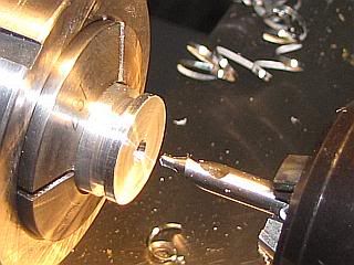
The front bearing is another turning similar to the center bearing. Again bronze (SAE 660) is used. This time it is turned to 0.375 diameter. Length is 0.023 longer than the front bearing housing. The oil passage (0.005 X 0.062) is only put in on one end, and that end will face to the inside of the crankcase. It is reamed to 0.250, which is larger than on the Mk1 which was 6mm to match the ball bearings that have disappeared on the Mk2. After cleaning both the bearing OD and the bore of the housing the parts are Loctited together same as was done on the center bearing assembly. This time however, the bearing wants to be flush on the nside the crankcase with about 0.005 sticking out beyond the front of the bearing housing.
Gail in NM
Gail in NM
- Joined
- Feb 17, 2008
- Messages
- 2,326
- Reaction score
- 440
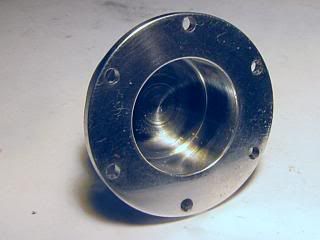
The rear cover is basically the same as the Mk1 except that it has a O-ring groove cut into it to eliminate the gasket. The depth of the of the groove made it necessary to reduce the diameter of the lightning cutout in the back of it by 0.062 inch.
Gail in NM
Gail in NM
The most recent version is looking good, Gail. I like the idea of O-rings, (and thanks for explanations).
Good thinking using paper for your locating spacer on the bearing. I would have been looking through my brass shim stock. Sometimes, or often, the most sensible idea isn't the first one that pops into my head!
Dean
Good thinking using paper for your locating spacer on the bearing. I would have been looking through my brass shim stock. Sometimes, or often, the most sensible idea isn't the first one that pops into my head!
Dean
- Joined
- Feb 17, 2008
- Messages
- 2,326
- Reaction score
- 440
Thanks Dean,
I use paper for setup spacers like that. Besides the 0.003 and 0.005 for the light and heavy weight copy papers, my 3X5 index cards are 0.0075 so two of them stacked up make 1/64 inch close enough.
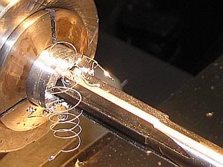
With the front bearing done, the front crankshaft can be made and fitted to the front bearing. It is the same procedure as was done on the Mk1 but a few dimensions have changed. Most notable is the change from 6mm main shaft to 0.3125 to suit the imperial sized 5/16 reamer I used for the front bearing bore.
Gail in NM
I use paper for setup spacers like that. Besides the 0.003 and 0.005 for the light and heavy weight copy papers, my 3X5 index cards are 0.0075 so two of them stacked up make 1/64 inch close enough.
With the front bearing done, the front crankshaft can be made and fitted to the front bearing. It is the same procedure as was done on the Mk1 but a few dimensions have changed. Most notable is the change from 6mm main shaft to 0.3125 to suit the imperial sized 5/16 reamer I used for the front bearing bore.
Gail in NM
Powder keg
Well-Known Member
- Joined
- Oct 10, 2007
- Messages
- 1,091
- Reaction score
- 3
Looks like you are staying busy ) Nice job.
) Nice job.- Joined
- Feb 17, 2008
- Messages
- 2,326
- Reaction score
- 440
Thanks Tony and Wes.
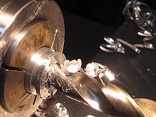
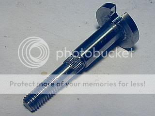
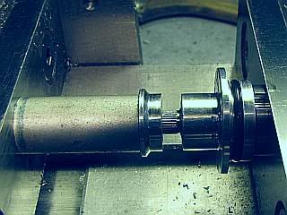
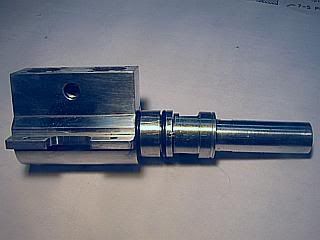
The center crankshafts turned and ready to assemble to the center bearing assembly. I had to make up a new crankpin turning fixture as the the main shaft diameter was changed from 8mm to 0.3125 on the front half of the center crankshaft. This was done so I could use an imperial reamer to make the bearing.
Gail in NM
- Joined
- Feb 17, 2008
- Messages
- 2,326
- Reaction score
- 440
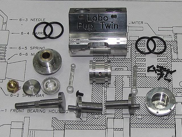
A few small parts were made that were unchanged from the Mk1 version. The prop driver, prop washer and prop nut.
Adding a button head 4-40 x 3/16 screw, a dozen 0-80 X 3/16 socket head cap screws and 4 o-rings gives us all the parts necessary to build the bottom end of the Lobo Pup Twin. In addition some Loctite retain compound will be used to assemble the center crankshafts.
Gail in NM
Adding a button head 4-40 x 3/16 screw, a dozen 0-80 X 3/16 socket head cap screws and 4 o-rings gives us all the parts necessary to build the bottom end of the Lobo Pup Twin. In addition some Loctite retain compound will be used to assemble the center crankshafts.
Gail in NM
- Joined
- Feb 17, 2008
- Messages
- 2,326
- Reaction score
- 440
Before assembly is started, everything was cleaned with alcohol saturated paper towel strips. The crankcase is likely to have traces of polishing compound in various holes and needs to be flushed out.
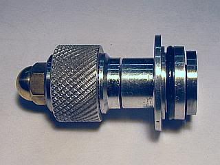
Assembly is started with inserting the front crankshaft into the front bearing. Before inserting, the crankshaft is lubed using regular 20 weight machine oil. When running it will get replaced with the castor oil in the fuel. The Prop driver is pressed on the crankshaft in my milling vice using a length of bar that has been drilled 3/16 and the ends faced so they are parallel. Then a test knurled knob is attached to the crankshaft to make adjustment easier later. An o-ring is installed on the front bearing housing.
Assembly of the center bearing assembly with the two center crankshafts requires a bit of care. Most important is that no Loctite get into the bearing. It is easy enough if precautions are taken. I inserted the front half of center crankshaft into the bearing from the end of the bearing housing that does not have the notches used to align the housing in the crankcase. It is lubed with machine oil as it is inserted. After inserting, the inside of the crankshaft is cleaned using alcohol and a cotton swab. This is to make sure that no oil has gotten into the crankshaft. Loctite retaining compound is placed inside the crankshaft, making sure that no compound gets on the bearing. Then the rear half of the crankshaft is inserted with a rotating motion to distribute the Loctite. The assembly is placed into the alignment fixture and every thing pressed down so the bearing housing and both crankpins are touching the housing. Notice the o-rings have not yet been installed on the bearing housing. After the Loctite is set the O-rings are installed on the bearing housing.
Gail in NM
- Joined
- Feb 17, 2008
- Messages
- 2,326
- Reaction score
- 440
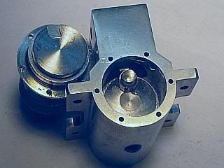
Put a drop of oil on each o-ring. Using the insertion tool, insert the center crankshaft assembly into the crankcase and align the 4-40 clearance and tapped hole. Insert the 4-40 x 3/16 screw in the bottom of the crankcase to secure the crankshaft assembly.
After applying machine oil to the crankpin, install the front connecting rod through the cylinder hole in the crankcase on the front crankpin. Then insert the front bearing assembly while looking through the cylinder hole to align the slot in the front crankshaft. Secure with 0-80 x 3/16 screws. Install the rear connecting rod with oil and then install the rear cover and secure with 0-80 screws. This completes assembly of everything below the top of the crankcase except the fuel system.
Gail in NM
- Joined
- Feb 17, 2008
- Messages
- 2,326
- Reaction score
- 440
Thanks Dean,
Assembly is logical. I just detailed it out so it looks more complicated.
I have the cylinder stock by the lathe so I can start on them in the morning. They should go fairly quickly as they are the same as the Mk1 version except for some relief for the con rods has to be added in the skirts.
Gail in NM
Similar threads
- Replies
- 7
- Views
- 2K
- Replies
- 1
- Views
- 561