
You are using an out of date browser. It may not display this or other websites correctly.
You should upgrade or use an alternative browser.
You should upgrade or use an alternative browser.
Lobo Pup Twin 1.6 cc diesel
- Thread starter GailInNM
- Start date


Help Support Home Model Engine Machinist Forum:
This site may earn a commission from merchant affiliate
links, including eBay, Amazon, and others.
Krown Kustoms
Well-Known Member
- Joined
- Aug 6, 2009
- Messages
- 313
- Reaction score
- 2
That looks great, did you blacken the cylinders or is it the camera angle?
-B-
-B-
- Joined
- Feb 17, 2008
- Messages
- 2,326
- Reaction score
- 440
Thanks Tony & -B-.
-B-
It's just the camera angle and my poor lighting. I plan to black oxide them in the oven at 550 degrees just before the final lapping. That way any heat distortion will be lapped out as the final step.
Gail in NM
-B-
It's just the camera angle and my poor lighting. I plan to black oxide them in the oven at 550 degrees just before the final lapping. That way any heat distortion will be lapped out as the final step.
Gail in NM
Krown Kustoms
Well-Known Member
- Joined
- Aug 6, 2009
- Messages
- 313
- Reaction score
- 2
They definately look good darker than the rest.
-B-
-B-
- Joined
- Feb 17, 2008
- Messages
- 2,326
- Reaction score
- 440
Tony,
This is done with out chemicals. Just formation of the oxide by heating the part. Some of us played with this a couple of months ago. Details are at:
http://www.homemodelenginemachinist.com/index.php?topic=5514.msg58087#msg58087
Gail in NM
This is done with out chemicals. Just formation of the oxide by heating the part. Some of us played with this a couple of months ago. Details are at:
http://www.homemodelenginemachinist.com/index.php?topic=5514.msg58087#msg58087
Gail in NM
Krown Kustoms
Well-Known Member
- Joined
- Aug 6, 2009
- Messages
- 313
- Reaction score
- 2
I Found a mix a few years ago using chemicals, I had to modify it a bit but it "blues" really well.
You dont want this stuff in the kitchen it has a strong oxidiser and a lot of caustic lye in it.
After I use it I evaperate the water and put the powder in a air tight can for future use.
It definatly is not the most logical way if all you have to do is heat the metal, There is a duribility issue but most parts I do are cosmetic so just the heat will do for now on and its safer. (well maybe not, if my wife catches me with a bunch of steel in the oven)
thanks for the tip
-B-
- Joined
- Feb 17, 2008
- Messages
- 2,326
- Reaction score
- 440
Tony and -B-,
I have had mixed results using chemical blackening. Probably not getting parts clean enough. I have chemicals for parkerizing but have not done anything with them yet. I do like the finished produced from photos I have seen.
This will be the first time I have used the heat only treatment on real parts. Only done test parts so far. I like the blue/black look and durability seems to be OK, comparable to the chemical treating I have done in the past.
In the meantime, I have to get the cylinders up to the point of finishing first.
The only thing done since the last construction post is to drill the mounting holes in the cylinders and clean up the burrs.
The cylinders were clamped in the mill vice using a "V" block. Worked out just right as the cylinder length is only a little bit shorter than my vice jaws are tall. I have a "V" block that I made up to the same height as the vice jaws for just this sort of thing. I modified a General Hardware "V" block as they are cast iron and not hardened. Easy enough to saw off the extra length and then finish up the sawed edge in the mill.
After clamping in the vice, I indicated the center of the bore and then center drilled and drilled the mounting holes using the coordinates from the drawing. The drill of course made burrs, so back to the lathe and the burrs were cleaned off on both end fins and between the fins using 400 grit abrasive paper folded around a 6 inch rule. I run the lathe in reverse so the paper is under tension. If you run the lathe in forward and work on the top side of the part the paper can bunch up and grab and try to drive the rule into your hand. Not a good thing. If your lathe cannot be reversed, work from the bottom of the part so the paper is under tension. In either case, do not try to steady the other end of the rule with your other hand. The results can be painful.
Gail in NM
- Joined
- Feb 17, 2008
- Messages
- 2,326
- Reaction score
- 440
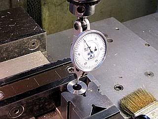
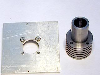
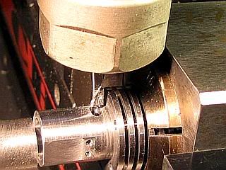
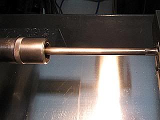
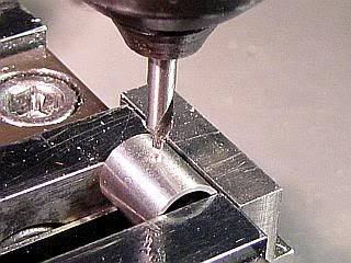
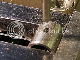
With the mounting holes in place it is time to put the ports in the cylinder. I used a 5c square collet block to hold the cylinder. The mounting holes were put in first because the ports can be easily aligned to them using a fixture. Actually you can align everything with out a fixture using a couple of rods in the holes and a parallel across the bolts and a level on top of than and then tightening the collet with your fourth hand. I find that it is quicker to make up the fixture, even when only a few parts are involved.
The fixture is just a piece of scrap plate that is squared up to the same dimensions as my square collet block. I used 0.09 aluminum. An oversize 1/2 inch diameter hole is put in the center of the plate. I used a 1/2 inch end mill to punch the hole through and then bumped the table plus and minus about 0.003 inch in both the X and Y axis. It's just clearance for the 1/2 spigot on the cylinder, so I don't care if it is perfectly round. Then 4 holes were coordinate drilled for tapping 2-56 to match the mounting holes in the cylinder. After tapping, two 2-56 were inserted. I found the screw heads were slightly protruding into the 1/2 hole space, so I touched them with a round file for clearance. This just keeps them from catching on the cylinder when the fixture is slid on the cylinder.
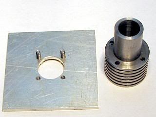
The fixture is engages with two of the holes in the cylinder and the cylinder is inserted into the collet and the collet is tightened while both the block and fixture are on a flat surface.
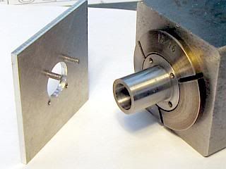
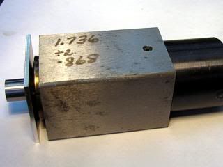
A stop is set up on the mill to register on the end of the cylinder. Any kind of stop can be used, but it needs to be below the top of the 1/2 diameter of the cylinder so a flat can be milled on the cylinder with out hitting the stop. I have two vices on my mill, so I used the second vice to support the stop, using a "V" block and a spacer to hold the stop level and position it. I used an edge finder to locate the end of the stop and zeroed the X axis. I put the collet block in the vice and then located the center line of the cylinder using the edge finder and zeroed the Y axis on the center line. I then milled the flat on the cylinder using a 1/2 end mill.
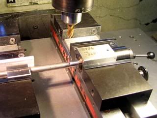
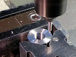
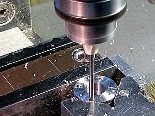
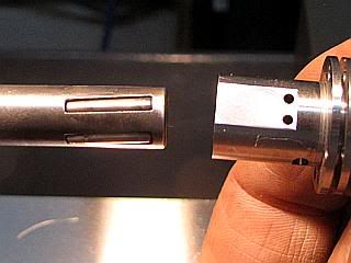
I had intended to just rotate the collet block to do the work on the second, third, and fourth sides of the cylinder, but quickly realized that I did not have room for the collet chuck holding the small end mills to clear the 5C collet. So I reset the cylinder in the collet block so an additional 1/4 inch or so protruded. The position of the cylinder in the collet block is of no importance, other that support, as all the measurments are referenced to the end of the cylinder as set by the stop on the table. Even if I had set the cylinder in the protruding position first, after milling the flat, the end of the cylinder needs to have the burr removed from the end so it does not affect the position of the cylinder.
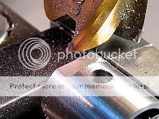
The Intake and Transfer ports were "drilled" using a 1/16 end mill and the Exhaust port was milled with a 3/32 end mill. The holes were drilled with an end mill as they are starting on a sloped surface for the intake port as they are off center line. Both end mills have to be center cutting. Also, a end mill leaves less burr on the inside of the cylinder so it is easier to remove prior to lapping the cylinder.
Gail in NM
The fixture is just a piece of scrap plate that is squared up to the same dimensions as my square collet block. I used 0.09 aluminum. An oversize 1/2 inch diameter hole is put in the center of the plate. I used a 1/2 inch end mill to punch the hole through and then bumped the table plus and minus about 0.003 inch in both the X and Y axis. It's just clearance for the 1/2 spigot on the cylinder, so I don't care if it is perfectly round. Then 4 holes were coordinate drilled for tapping 2-56 to match the mounting holes in the cylinder. After tapping, two 2-56 were inserted. I found the screw heads were slightly protruding into the 1/2 hole space, so I touched them with a round file for clearance. This just keeps them from catching on the cylinder when the fixture is slid on the cylinder.
The fixture is engages with two of the holes in the cylinder and the cylinder is inserted into the collet and the collet is tightened while both the block and fixture are on a flat surface.
A stop is set up on the mill to register on the end of the cylinder. Any kind of stop can be used, but it needs to be below the top of the 1/2 diameter of the cylinder so a flat can be milled on the cylinder with out hitting the stop. I have two vices on my mill, so I used the second vice to support the stop, using a "V" block and a spacer to hold the stop level and position it. I used an edge finder to locate the end of the stop and zeroed the X axis. I put the collet block in the vice and then located the center line of the cylinder using the edge finder and zeroed the Y axis on the center line. I then milled the flat on the cylinder using a 1/2 end mill.
I had intended to just rotate the collet block to do the work on the second, third, and fourth sides of the cylinder, but quickly realized that I did not have room for the collet chuck holding the small end mills to clear the 5C collet. So I reset the cylinder in the collet block so an additional 1/4 inch or so protruded. The position of the cylinder in the collet block is of no importance, other that support, as all the measurments are referenced to the end of the cylinder as set by the stop on the table. Even if I had set the cylinder in the protruding position first, after milling the flat, the end of the cylinder needs to have the burr removed from the end so it does not affect the position of the cylinder.
The Intake and Transfer ports were "drilled" using a 1/16 end mill and the Exhaust port was milled with a 3/32 end mill. The holes were drilled with an end mill as they are starting on a sloped surface for the intake port as they are off center line. Both end mills have to be center cutting. Also, a end mill leaves less burr on the inside of the cylinder so it is easier to remove prior to lapping the cylinder.
Gail in NM
")
- Joined
- Feb 17, 2008
- Messages
- 2,326
- Reaction score
- 440
Thanks Arnold. Third hand reserved for scratching head while saying "why did it do THAT."
Finishing up the cylinders.
With all the machining done, all that is left on the cylinders is to finish the bore and blacken them.
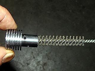
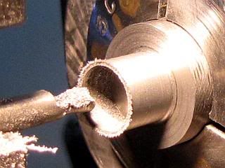
Since I had a Flex-Hone the right size, I ran it in and out of the cylinder one time using a low speed drill. This is to remove the bulk of the burrs caused by machining through the cylinder walls. I used some light oil on the Flex-Hone. When I don't have a Flex-Hone, I just use a bit of 400 grit abrasive paper wrapped around a convenient size rod or wood dowel.
Then I cleaned the bore to remove any oil, swarf and abrasive that might have come from the Flex-Hone. I use a nylon tube brush and mineral spirits.
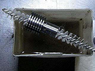
I rough finished the bore to size using a Cogsdill roller burnishing tool that I bought at the right price at an auction. They work by exerting high pressure on the peaks in a bore and deforming them into the valleys. Very quick and easy, but it will not improve the geometry very much, so the bore has to be round and consistent. Most of the time I lap the bore to get it to this point. For information on how I do the lapping, both rough and finishing, see my PMC IMP thread starting at post #40. It details this stage and the next one also.
http://www.homemodelenginemachinist.com/index.php?topic=4422.msg50150#msg50150
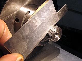
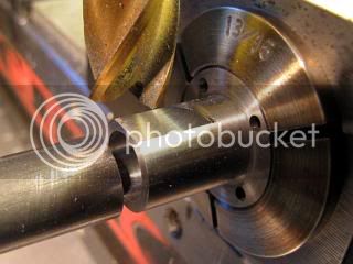
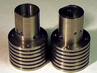
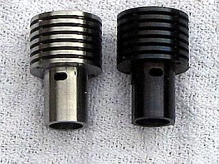
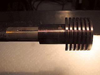
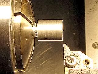
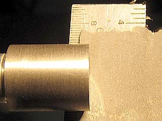
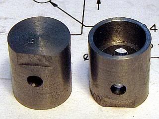
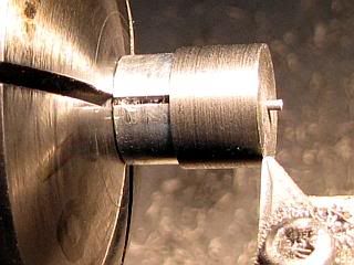
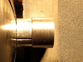
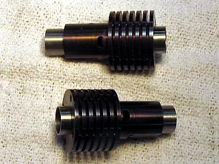
With the bore roughed out, I blackened the cylinders. First they were cleaned with solvent. I used acetone as it drys quickly and leaves no residue. Then they were placed in the domestic oven with the oven set a 550 degrees F. I left them there about 30 minutes after the oven reached temperature. The results are shown below, with a untreated cylinder beside a blackened one. I had made an extra cylinder "just in case" so I had it for the photo.
After they were cool, it was back to the lathe for the final bore finishing. I measured and tested the bore with plug gauges before finishing to see if there was any distortion caused by heating, but could not find any. Finishing was done with a brass lap using 5 micron diamond polishing compound. I ran it through the bore just enough to remove the black oxide coating, and then continued on to taper the bore an additional 0.0002 at the bottom end up to just above the exhaust ports. The reasons and procedure is detailed in the PMC IMP thread referenced above.
The last step is to clean the cylinders very well. I used a brush and mineral spirits, then detergent and hot water. After drying, they were coated with light oil to prevent any rust.
Gail in NM
Finishing up the cylinders.
With all the machining done, all that is left on the cylinders is to finish the bore and blacken them.
Since I had a Flex-Hone the right size, I ran it in and out of the cylinder one time using a low speed drill. This is to remove the bulk of the burrs caused by machining through the cylinder walls. I used some light oil on the Flex-Hone. When I don't have a Flex-Hone, I just use a bit of 400 grit abrasive paper wrapped around a convenient size rod or wood dowel.
Then I cleaned the bore to remove any oil, swarf and abrasive that might have come from the Flex-Hone. I use a nylon tube brush and mineral spirits.
I rough finished the bore to size using a Cogsdill roller burnishing tool that I bought at the right price at an auction. They work by exerting high pressure on the peaks in a bore and deforming them into the valleys. Very quick and easy, but it will not improve the geometry very much, so the bore has to be round and consistent. Most of the time I lap the bore to get it to this point. For information on how I do the lapping, both rough and finishing, see my PMC IMP thread starting at post #40. It details this stage and the next one also.
http://www.homemodelenginemachinist.com/index.php?topic=4422.msg50150#msg50150
With the bore roughed out, I blackened the cylinders. First they were cleaned with solvent. I used acetone as it drys quickly and leaves no residue. Then they were placed in the domestic oven with the oven set a 550 degrees F. I left them there about 30 minutes after the oven reached temperature. The results are shown below, with a untreated cylinder beside a blackened one. I had made an extra cylinder "just in case" so I had it for the photo.
After they were cool, it was back to the lathe for the final bore finishing. I measured and tested the bore with plug gauges before finishing to see if there was any distortion caused by heating, but could not find any. Finishing was done with a brass lap using 5 micron diamond polishing compound. I ran it through the bore just enough to remove the black oxide coating, and then continued on to taper the bore an additional 0.0002 at the bottom end up to just above the exhaust ports. The reasons and procedure is detailed in the PMC IMP thread referenced above.
The last step is to clean the cylinders very well. I used a brush and mineral spirits, then detergent and hot water. After drying, they were coated with light oil to prevent any rust.
Gail in NM
- Joined
- Feb 17, 2008
- Messages
- 2,326
- Reaction score
- 440
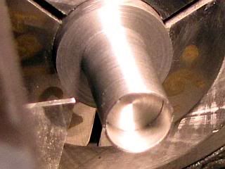
With the cylinders finished, it is time to fill them up. Piston, contra piston, and wrist pin.
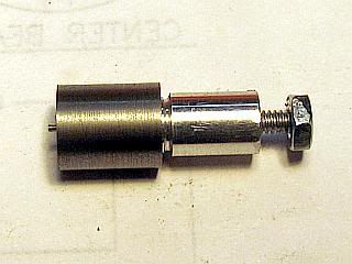
Before starting the piston and contra piston, I made a pair fo internal expanding mandrels to grip them for the finish polishing and fitting operations.
They are just a aluminum rod turned to fit the inside dimensions of the piston and contra piston with a chucking section. They are drilled, and the chucking section threaded 4-40 and the mandrel end has a clearance hole for a 4-40 and a counter sink on the end for the flat head of the 4-40 bolt. The bolt is inserted and threaded through and a nut is Locktited on the end of the bolt to make turning it easy.
Gail in NM
- Joined
- Feb 17, 2008
- Messages
- 2,326
- Reaction score
- 440
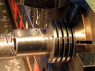
The pistons are made of cast iron. The smallest easily available cast iron stock is a nominal 5/8 inch diameter. It always comes oversize so it can be cleaned up to the nominal dimension. When I get a new piece in I turn it between centers until it just cleans up to get rid of the scale and bring it round. Then I turn the diameter down to the nearest standard collet that I have. In this case it is 0.672. This gives me nice stock to work with.
I started by measuring the two cylinders ID. Then I turned a little over an inch down to a diameter about 0.0005 larger than the larger of the two cylinders. I bored the stepped inside diameters and then cut off leaving about 0.005 inch long for cleaning up to the length dimension. Repeated the boring and cutoff operations for the second cylinder. This was OK because by two cylinders were only about 0.0003 inch different on the ID. If they had been more than 0.001 I would have dusted off a little bit more with the turning tool for the smaller cylinder. You don't have to do accurate measurements in doing all this. Just turn the stock down until it almost goes into the cylinder. Remember the cylinder is slightly tapered, so check at the bottom end.
The piston for the larger ID cylinder was mounted on the mandrel. I always start with the largest ID cylinder because if I polish the piston down too far, I can fit it to a smaller cylinder.
After measuring the length of the piston, I faced it off to bring it to drawing length. Then I polished the piston with 1200 grit abrasive paper backed with a 6 inch machinist rule. I would polish a little and then try to fit it in the cylinder. The goal is for the piston to jam with about 2 pounds force when the bottom of the piston just clears the intake ports in the cylinder.
Over to the milling machine, where the wrist pin hole is center drilled, drilled and reamed. I center drill a little deeper than I would on a flat surface as the drill will try to deflect due to the curved outer surface of the piston.
While still clamped in the mill vice, I milled away the bit of the piston that forms the transfer notch on the piston.
Gail in NM
zeeprogrammer
Well-Known Member
- Joined
- Mar 14, 2009
- Messages
- 3,362
- Reaction score
- 13
Continues to be an interesting thread (no surprise there).
Thanks for showing the expanding mandrels. I have seen references to such things but could never figure out what they really were or how they worked. This helped a lot.
In an earlier post you described putting the cylinder in a 550F oven for 30 minutes and that this blackened them. You did nothing else but back them? Was there any oil covering on them? Once blackened is there still concern for rust?
Your pics are top quality. Do you use any special lighting?
Very interesting stuff. I don't say much here but I'm always looking.
- Joined
- Feb 17, 2008
- Messages
- 2,326
- Reaction score
- 440
Thanks for the comments Carl,
I have not had much shop time for the last couple of days, but I think I am back on track now. If you look at the last photo in my last post, the piston on the right has a few marks just to the left of the flat on the crown of the piston. I had not clamped the piston tight enough when milling the flat and it rotated. The scars polished out enough that the piston would work OK, and once assembled nobody but me would know they were there. But, I would know they were there, so I mane a new piston to replace it. I also spent a few hours on machine preventative maintainance. I am now set up to start the contra pistons.
Since there is nothing done worthy of a photo, I wanted to answer Zee's questions.
The cylinders had no coating on them when they were put in the oven. They had been cleaned very well and all oils removed. The color is just the natural color of oxidation of the steel. If you Google "steel color temperature" you will find many color charts showing the colors at various temperatures. It gets the darkest at about 550 degrees F. The temperature is fairly critical as the color changes rapidly as you go through the 450 to 600 degree range. If you try it, try some scrap first as domestic ovens are not always calibrated very well. The oxide coating will provide very little, if any, corrosion protection, so the parts need to be oiled afterwards. The same is true of cold chemical blackening treatments. Parkerizing will provide good corrosion resistance, but will not be as black and uses heated solutions which I am not fond of.
For photos, I do not use any special lighting. Photos on the lathe are lighted by a 50 watt halogen work lamp. On the mill I have a 50 watt halogen lamp and a 23 watt fluorescent screw in bulb in articulated lamps. I position the lamps to minimize unwanted reflections. I use a macro setting on the camera, but to get a greater depth of field, I back up until the image only fills about 1/3 of the frame. I use a 10MP camera so there is lots of resolution to throw away. I generally put a white index card in an area outside the area that I will be cropping the image to. I do not set the light color temperature on the camera. It's a pain to do with the camera that I am using. Then I process the photo on the computer.
I use a simple photo editor called "click 2 crop" It's greatest virtue is that it is quick. I have more capable editors, but they take far more time to use. It is available at: http://www.mazaika.com/click2crop.html
Costs about US$20, but you can download it and try it free for a week or two.
I mentioned a white card earlier. Before cropping, put the cursor on the white card and right click the mouse and it will adjust for the color temperature of your lighting. There is an auto adjust box that cleans up a lot of contrast problems also. Then I set the output format that I want. For this thread I am using 320 x 240 pixel output. Drag the crop lines around to get what you want on the original, and the follow on the output image shown on the split screen. For most of the images I use a sharpen tool and there are 4 levels of sharpening. If there are dark shadows in an area of interest I tweak the gamma a little bit. It really works on this program, at least I like the look for illustration purposes. I really like the program as you can tell. It has more features that I don't use, but the main thing is that it is fast. On average, I don't spend more than 15 seconds on a photo.
Tomorrow will be contra piston day, and maybe wrist pins.
Gail in NM
zeeprogrammer
Well-Known Member
- Joined
- Mar 14, 2009
- Messages
- 3,362
- Reaction score
- 13
Thank you very much Gail. Excellent information, very helpful, and very much appreciated.
- Joined
- Feb 17, 2008
- Messages
- 2,326
- Reaction score
- 440
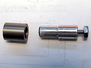
On to the contra pistons. A couple of days late, but still onward.
Most of the operations are similar to the pistons, but with a couple of exceptions. The contra piston has a very thin wall on the skirt. This is to allow the skirt to be compressed slightly to form a tight seal in the cylinder. To make this work, the contra piston is tapered very slightly so the skirt is slightly larger than the crown. I have not measured the amount because the pressure of the micrometer anvil distorts the skirt. The other special requirement is that the bottom of the recess forming the skirt needs to be fairly flat and smooth so the compression adjustment screw will have a good surface to press on.
Same set up as for the piston except I turned down enough of the cast iron bar to make three contra pistons instead of two pistons. I wanted an extra because it is a little more difficult to polish the contra piston to have the taper than to do the straight sided piston. I turned the stock to about 0.001 oversize from the cylinder bore.
Next bore it to leave a 0.015 wall. I used a boring bar that was small enough that I could face the bottom of the recess with it.
The part was cut off about 0.010 long to allow some stock to clean up to length. Then the other two contra pistons were made to same point. After mounting the contra piston to the expanded mandrel, the contra piston was brought to length.
Polishing the contra to size is the most difficult part. It is not really difficult, but it does require a little bit of a feel. That's the reason I made three blanks. I did not need the extra blank, but it is comforting to have it in case because it is easy to make the contra too small.
Before starting, remove the piston from the cylinder and mark both the cylinder and piston so they can be kept as a set. During the following operations the cylinder needs to be open so the contra piston can be pressed out while sizing it to the cylinder. It is "awkward" to have the piston in one end and the contra stuck in the other end of the cylinder and no easy way to remove either one of them.
I started with 400 grit abrasive paper backed with a machinist rule. I put a bit more pressure on the crown end until the the crown would almost enter the cylinder. Then I switched to 1200 grit paper and continued polishing until about 1/3 of the contra piston would enter the cylinder with about a pound of force. Remove the contra piston from the mandrel and test fit it in the cylinder. It should take about 2 to 4 pounds of force to get it to enter the cylinder completely. If it is to tight put in back in the lathe and continue polishing the skirt until it does fit. If (when) the contra piston gets stuck in the cylinder, it can be driven out using a soft rod while supporting the cylinder over an opening. I use the mill vice with the jaws opened up to about 1/2 inch. When finished, mark the contra piston so keep it with the corresponding cylinder and piston.
Gail in NM
- Joined
- Feb 17, 2008
- Messages
- 2,326
- Reaction score
- 440
Thanks Arnold.
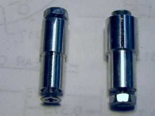
Wrist pins. Whats there to say about wrist pins.They have to be the right size, round, smooth, and tough.
On most of my engines in this size range, I have used music wire from the local hobby shop. The stuff that is straightened and comes in 3 foot lengths. That is what I intended to use on this engine. But, it is typically slightly under size by a small amount and sometimes not perfectly round. So I run an external lap over it to bring round and reduce the size to 0.0930 from the nominal 0.0938. I have a under size reamer that works well at this size when used on the mating parts. Well, being an old man with CRS syndrome I forgot to use the under size reamer and used my standard 3/32 reamer for the connecting rods and the pistons. Therefore the music wire at hand was under size and unusable.
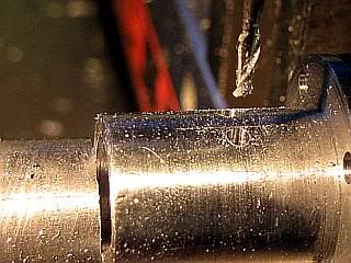
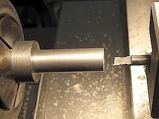
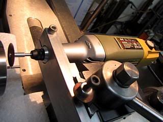
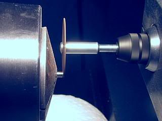
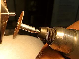
Two alternatives were available. I could use drill rod (silver steel) and harden, polish and temper it, or I had some 3/32 HSS drill blanks. I went with the drill blanks. Since they are already hard, all work on them was done with a grinder. I use a Proxxon IB/E rotary tool on the lathe. It is their industrial rotary tool with preloaded ball bearings on the spindle. About the same size as a corded Dremel, but rated for continuous duty. The nice thing about it is the nose is all metal, and machined for mounting in a 20mm hole. I have mounts made up for my mill spindle housing and for the QCTP on the lathe. I used a standard Dremel cutoff wheel for all the grinding.
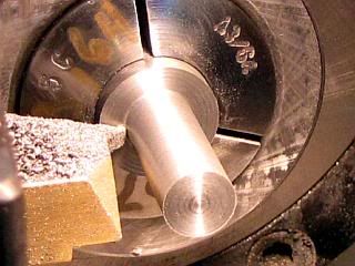
Drill blank was put in the lathe collet and the Proxxon mounted on the QCTP. Note the paper towels covering all the slides and lathe bed to protect them from grinding debris. First operation was to square up the end of the blank (no photo) and then advance the lathe carriage the finished length of the wrist pin plus the thickness of the wheel plus about 0.005 more just in case.
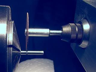
After cutting almost all the way through the pin, I snapped the pin off pliers after retracting the cutoff wheel. After cutting both pins, they were reversed in the lathe and ground to length. The length needs to be less than the cylinder ID by about 0.005 inch.
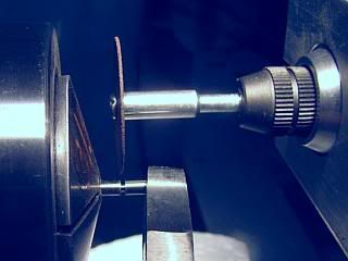
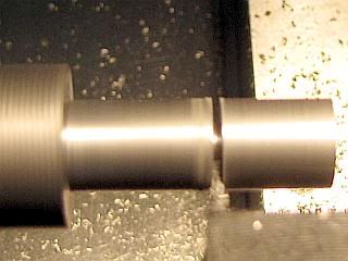
Finally each end of the pin is radiused and polished hand holding the rotary tool. If you look closely in the last photo, you can see the radius being developed.
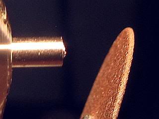
The wrist pins on the Lobo are floating, that is there is no method for retaining them in position. Therefore they can contact the cylinder wall. That is the reason that the ends must be polished so they do not damage the cylinder. Note that when the pin passed the intake and transfer ports on the cylinder, it can ride on the bridge left between the two holes forming each of the ports.
Gail in NM
Wrist pins. Whats there to say about wrist pins.They have to be the right size, round, smooth, and tough.
On most of my engines in this size range, I have used music wire from the local hobby shop. The stuff that is straightened and comes in 3 foot lengths. That is what I intended to use on this engine. But, it is typically slightly under size by a small amount and sometimes not perfectly round. So I run an external lap over it to bring round and reduce the size to 0.0930 from the nominal 0.0938. I have a under size reamer that works well at this size when used on the mating parts. Well, being an old man with CRS syndrome I forgot to use the under size reamer and used my standard 3/32 reamer for the connecting rods and the pistons. Therefore the music wire at hand was under size and unusable.
Two alternatives were available. I could use drill rod (silver steel) and harden, polish and temper it, or I had some 3/32 HSS drill blanks. I went with the drill blanks. Since they are already hard, all work on them was done with a grinder. I use a Proxxon IB/E rotary tool on the lathe. It is their industrial rotary tool with preloaded ball bearings on the spindle. About the same size as a corded Dremel, but rated for continuous duty. The nice thing about it is the nose is all metal, and machined for mounting in a 20mm hole. I have mounts made up for my mill spindle housing and for the QCTP on the lathe. I used a standard Dremel cutoff wheel for all the grinding.
Drill blank was put in the lathe collet and the Proxxon mounted on the QCTP. Note the paper towels covering all the slides and lathe bed to protect them from grinding debris. First operation was to square up the end of the blank (no photo) and then advance the lathe carriage the finished length of the wrist pin plus the thickness of the wheel plus about 0.005 more just in case.
After cutting almost all the way through the pin, I snapped the pin off pliers after retracting the cutoff wheel. After cutting both pins, they were reversed in the lathe and ground to length. The length needs to be less than the cylinder ID by about 0.005 inch.
Finally each end of the pin is radiused and polished hand holding the rotary tool. If you look closely in the last photo, you can see the radius being developed.
The wrist pins on the Lobo are floating, that is there is no method for retaining them in position. Therefore they can contact the cylinder wall. That is the reason that the ends must be polished so they do not damage the cylinder. Note that when the pin passed the intake and transfer ports on the cylinder, it can ride on the bridge left between the two holes forming each of the ports.
Gail in NM
Similar threads
- Replies
- 7
- Views
- 2K
- Replies
- 1
- Views
- 681