Lobo Pup Twin 1.6 cc diesel

Home Model Engine Machinist Forum

Help Support Home Model Engine Machinist Forum:

This site may earn a commission from merchant affiliate links, including eBay, Amazon, and others.
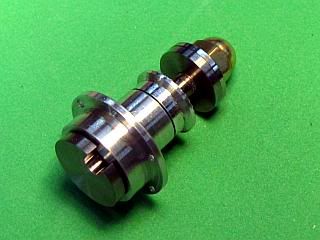
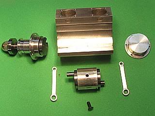
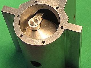
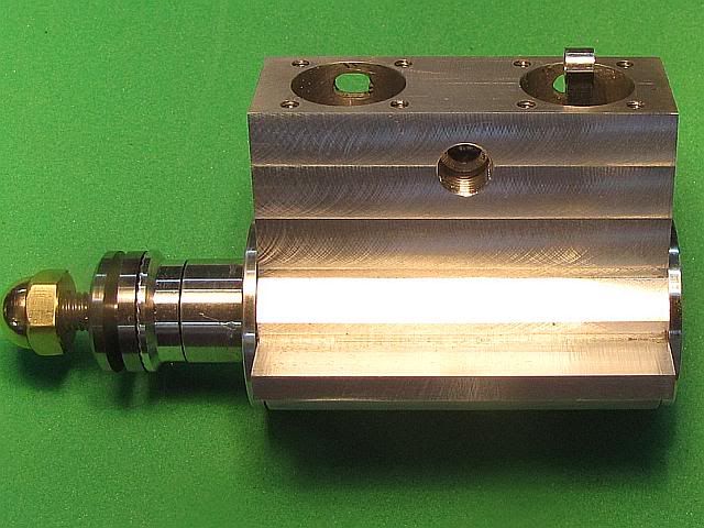
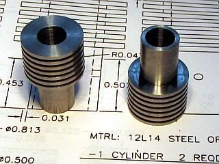
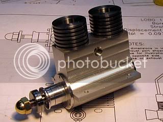
While the 1 inch aluminum stock was in the lathe for the front bearing, I also turned the blank for the rear cover. So, they were sort of made at the same time, jumping back and forth between them since many of the operations were similar.

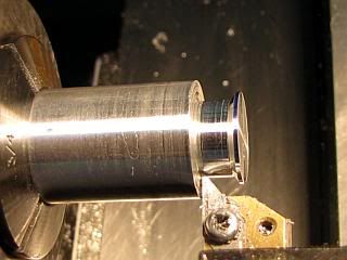
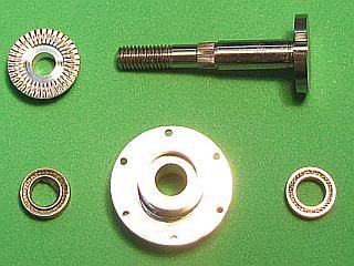
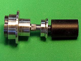
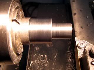
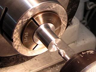
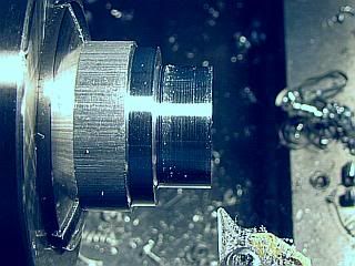
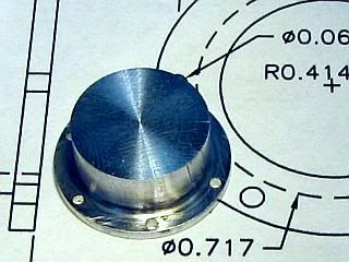
Started the rear cover by turning the two outside diameters and cleaning up the radius left by the tool using a parting tool so the cover would fit all the way into the crankcase.

RearCover1.jpg
RearCover2.jpg


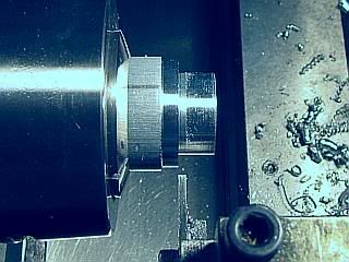
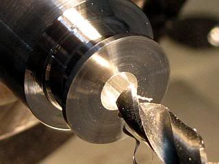
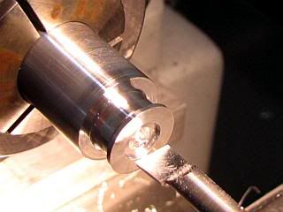
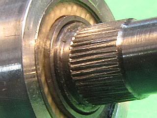
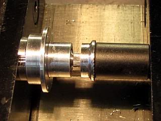
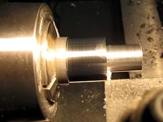
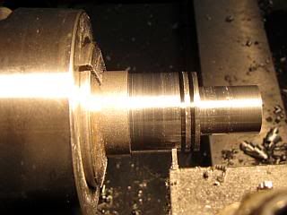
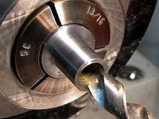
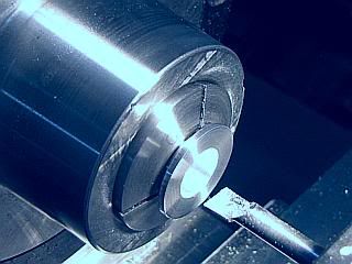
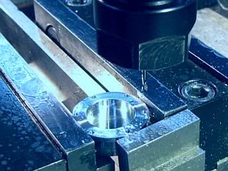
After cutoff, leaving a bit to cleanup, the part was reversed in the lathe and the flange faced to thickness and the recess in the rear was bored. Then over to the mill where the six mounting holes were put in with the same setup used for the front bearing housing, and using the same method of using a 1/16 end mill and coordinate drilling for location.

RearCover3.jpg
RearCover4.jpg
d

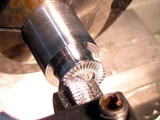
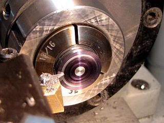
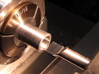
A little clean up and the rear cover is finished.

RearCover5.jpg


Gail in NM


Thank you for the update Gail - lovely work Thm:

Regards, Arnold
 
Diymania said:
Will be interesting to see how you´ll make the injectors and the injection pump.

Rof} Rof} Rof} Rof} Rof} Rof} Rof} Rof} Rof} Rof}

Maybe I shouldn't laugh knowing Gail
Tony
 
Thank your for the kind comments Tony and Arnold.

Diymania,
This is not a Diesel engine. It is a compression ignition engine. In the USA, Japan and several other countries model aircraft engines of this configuration are almost universally referred to as being a Diesel. Since this is a model aircraft engine, I referred to it as a Diesel. If I go into a hobby shop that deals with model aircraft and ask for a can of fuel for a compression ignition engine I will get a blank stare. If I ask for a can of Diesel fuel, I will get what I want, because that is the way it is labeled. It's not right, but that's the way it is.

Most of the time I refer to them as compression ignition engines. I intended to put this information in my initial post, but forgot.

And the real reason I called it a Diesel is because compression ignition would not fit on the subject line in the recent post column on this forum. As it turned out, neither did Diesel.

Gail in NM
 
GailInNM said:
And the real reason I called it a Diesel is because compression ignition would not fit on the subject line in the recent post column on this forum. As it turned out, neither did Diesel.
Ha, you're right... it does look like sad news, now that you mention it. ;D
 
Diymania
Sorry to laugh so hard. I work with a guy that has a sail boat with a diesel engine. I show him this site because he's an engineer and interested in all mechanical things. His comment to me was "they have carb's that's not a diesel you have to have injectors and they could never be made in that scale" My comment to him was "diesels where around long before injectors"
So Sorry again it just struck my funny bone
Tony
PS the engine was invented and named after Rudolph Diesel 1897 so to me it's a diesel if it runs on using compression for ign.
 
Diymania,
My tougths exactly. I googled compression ign eng and it took me to diesels and a HCCI eng. HCCI does it with Propane. What exactly do they mean by "injecting" Carb is an injector or sorts I've mess't with Radials and Opposed Aircraft eng (full size and models) 2 and 4 ciy's in model a/c, turbines and many car eng the same way. I never played with a Diesel in a truck, ship or train to know.

Did Mr diesel have injectors in the 1870's????

Gail
Please.....Please.... A history leason! stickpoke

Tony

 
Tony,
I do have a couple of good books in my library on the early Diesel engines, but would have to look for them. But from memory, and remember that I am an old man with CRS, here are some of the facts.

The first patent was issued to Rudolph Diesel in 1893 and his first operational demonstration engine was shown in 1897.

The patent was for direct fuel injection into the already compressed air in the cylinder, with the heat of compression providing the ignition. No air was injected with the fuel. The patent also covered the gradual injection of the fuel to give a more constant pressure in the cylinder providing a more uniform power stroke.

Rudolph Diesel's engines did not use diesel fuel as we know it. All his engines ran on peanut oil, and it was not until after his death that petroleum oil was used as a fuel. I probably did try petroleum oil in his experiments as he tried many different fuels. I think that it was a powdered coal that he tried that resulted in an explosion that almost killed him. His patent referred to the fuel only as "oil" without defining what kind. One of the reasons for peanut oil was to stimulate the economy in the rural area that he had close ties to. Also petroleum oil was less abundant in his area.

Rather than injection pumps, he used high pressure air to force the fuel into the injectors, but no air was injected into the cylinder.

So, the Lobo Pup is not a Diesel as it does not use injection of the fuel into the compressed air in the cylinder. I use the term Diesel only to conform to the common usage in the model airplane community as practiced by both the manufacturers and end users of the engines. The smallest engine that I know of that has used injection has been about 1 cubic inch displacement (16cc). I don't remember the details on it, but I have the here somewhere.

Tony, I hope that this tell you a little bit about what you wanted to know.

Back to machining. I am a better machinist than I am wordsmith. Of course that may not be saying much.

Gail in NM
 
Gail,
That said it all. Thank you my friend for the enlightenment. He did use injector from the beginning. I always thought that there was a carb involved somewhere in the history. Well what the heck do I know. Those engines run on marbles anyway :big:
Tony
 
Thanks for your clarification Diymania. I pulled one of my favorite books on the subject and refreshed my memory before bed last night. It has a chapter on Diesel's early experiments. He went through a lot before he got any useful power out of an engine. My memory is kind of like dynamic RAM in a computer. If it is not refreshed regularly it loses the stored information.

On to making parts. This time it is the bits and pieces that go on the front crankshaft so it can be assembled with the front bearing assembly for a test fit in crankcase.

The only thing really necessary for this is the prop driver (7-1) but I made the prop washer (7-2) and the prop nut (7-3) also to get them out of the way.

The prop driver is turned from 6061 aluminum. The only critical dimension is the 0.203 bore as it is pressed onto the knurled portion of the crankshaft. My angle on the 0.500 to 0.594 transition does not agree with the drawing, but it can really be any angle. Mine is at 37 degrees because I have a VBMT insert in my tool holder. The insert has a 35 degree included angle and is set in the tool holder at 2 degrees so I can use it for facing as well as turning. By using that angle I could machine all the external surface and the angle with one setting and with out having to use the compound slide on the lathe.

Then the bore was drilled by first center drilling, drilling undersize, and finishing with a 0.203 diameter drill.

PropDriver1.jpg
PropDriver2.jpg


The bore was stepped out to 1/32 deep, and as the diameter if this only provides a runout area for the knurling tool in the next step I just set the diameter of this counter bore by eye and did not measure it. I used a straight knurl to face knurl the driver so it would bite into a prop and not slip. You can make different patterns on the driver if desired by running the knurl above or below center, or by using a diagonal knurl. See the article at http://modelenginenews.org/techniques/prop_drivers.html
for more information on this if you are interested.

PropDriver3.jpg
PropDriver4.jpg


To cutoff, I first plunged in at the 0.188 long dimension until I reached 0.34 diameter. Retracted the tool and moved over an additional 0.010 inch and to widen the cut. After plunging to the 0.34 diameter I moved back 0.005 inch and cut off, thus leaving a 0.34 diameter shoulder on the prop driver. This step is so the driver will bear against the inner race of the front ball bearing if the crankshaft is pushed back while starting with an electric starter.Otherwise it could rub against the outer race or the bearing housing.

PropDriver5.jpg
PropDriver6.jpg


And a finished driver and a shot of the driver along with the prop washers and prop nut. I made two washers. One of them was chamfered for looks and a second one was made plain to use as a spacer if necessary for thin props. I cheated on the nut and used a commercial brass acorn nut because I had part of a box of them. Just a little bit of polish to knock off the oxidation as I have had them for at least 20 years.

PropDriver7.jpg
PropDriver8.jpg


Gail in NM

 
GailInNM said:
Then the bore was drilled by first center drilling, drilling undersize, and finishing with a 0.203 diameter drill.

Hello Gail. I usually see "center drill, drill, and ream" - because drilling is not necessarily true or round. This is the first time I've seen finishing with a drill. Is the 2nd drill then acting as a reamer? Can one depend on that? Thanks.

Thanks for showing the knurling too. For me, that was a tip.
 
Zee,
For this part reaming would have been a bit of overkill. Since this part presses on the knurled portion of the front crankshaft it is not necessary to have an excellent finish or even that the hole be round. I did want it to be reasonably to size. Drilling under size, in this case about 0.010 undersize, and then opening it up will size the hole to within about half a thousandth of an inch. Finish will be reasonably good. Not the quality of a reamed hole, but good enough in this case.

I believe in only working to the tolerance necessary on a part. You probably noticed that I did not measure the counter bore I put in the prop driver. Eyeball accuracy was close enough. Not that I could not have measured it and put in the size I put on the print, but it would have taken extra time without improving the part. I would rather build more toys than expend unnecessary time. The old adage around a manufacturing plant was if you want to know the easiest way to do a job, give it to a lazy person to do. Well, I am one of those lazy persons.

Gail in NM
 
With all the parts for the Front Crankshaft Assembly made it's time to put some more part together.

Before committing to anything that is hard to take apart, one check is necessary. That is that the crankshaft fits through the installed bearings with a little bit showing between the bearing and the knurled portion of the crankshaft. The bearings are slipped or pressed into the front bearing housing and the crankshaft inserted. If the dimensions are spot on, there will be 0.004 inch between the inner bearing race and the shoulder of the knurled section. The actual amount showing should be between zero and 0.010 inch. Mine was about 0.006.

If the shoulder is inside the bearing inner race the bearings will be in compression after pressing on the prop driver. This is not a good thing for the bearings.

If the shoulder is too far out of the bearing, then the crankshaft could slide back when starting and bind on the connecting rod. It would have to move back about 0.015 inch. This would only be during starting, so it would probably not be serious.

First photo shows the parts ready to test fit and the second photo shows the crankshaft shoulder protruding slightly through the bearing.

FrontAssy1.jpg
FrontAssy2.jpg


To begin the final assembly, if a bearing is slightly loose in the housing, it should be secured with Loctite in the same manner as was done for the center crankshaft assembly. A sleeve is used to press the prop driver in place. Just needs to have a hole larger than the 3/16 diameter of the crankshaft and be long enough that the crankshaft will not protrude when the prop drrver is seated. Mine came out of the scrap bin and was 1/2 inch diameter. I used my milling machine vice to press the prop driver on to the crankshaft.

FrontAssy3.jpg
FrontAssy5.jpg


And the assembled front end.
FrontAssy6.jpg


Gail in NM
 
With the exception of the fuel system, all the parts below the top of the crankcase are now complete. So I made a test assembly of the parts to check for clearances. It all has to be taken apart so I can clean up the tooling marks and do any polishing that I might want to do, so it is mostly just slipped together.

First photo shows all the parts. The center crankshaft assembly is slid into place and the front connecting rod slid on. Then the center bearing assembly is secured with a 4-40 X 1/4 button head cap screw. The rear connection rod is installed. One area that I have screwed up before is the connecting rod to crankcase clearance. I had checked and double checked on this engine, but I still wanted to check. I could always relieve the crankcase a little bit if need be. Well I lucked out this time. Keeping the connecting rod centered in the cylinder bore, I rotated the crankshaft to the minimum clearance position and all was well as shown in the second photo

TestAssy1.jpg
TestAssy2.jpg


The other clearances that I wanted to check were the rear crankpin to the rear cover and the front crankpin to the front bearing housing. Sliding them in place I could look down the cylinder bores to inspect them. Any amount of clearance would be OK as the clearance on both areas will increase by 0.006 on final assembly with the gaskets in place. Then the engine was rotated to make sure there were no tight spots.

It's beginning to look like these lumps of metal might make an engine yet. ;D

TestAssy3.jpg


Gail in NM
 
It's beginning to look like these lumps of metal might make an engine yet.
Gail, that and if I may add, it is turning into a lovely work of art as well.
Thank you very much!
Kind regards, Arnold
 
I'm with arnold, great working and documentation on this engine :bow:

thanks gail
 
I'm really enjoying this build... have I said that already? ;D
 
Gail it just gets better awesome job keep it going plzzz :bow:
wiat till you start her up :big: the smell ................i just love that smell of a model diesel engine .......to me thats a real model engine ,
thankz again keep it going :bow:
 
Arnold, Ariz, Vernon & Animate: Thanks for the encouragement and support.
I had some personal things to take care of the last couple of days, so not much got done until late this afternoon.

Going up from the crankcase, the cylinders are next. I made the cylinders from 7/8 inch diameter 12L14 steel. Things got started by facing the end and turning the two diameters forming the OD of the fins and the 1/2 diameter that goes into the crankcase. Then the radius of the cutter at the junction was squared up with a cut off tool.

Cyl1.jpg
Cyl2.jpg


Using the same cutoff tool, the fins were cut. The size of the fins and the spaces between them is not critical. The print dimensions were selected to match up with the 1mm wide cutoff blade I have. I would not reduce the top and bottom fin thickness too much however. Because model compression ignition engines tend to run cool, there is far more cooling fin area than is necessary, so about any fin configuration could be used.

The cylinder blank was cutoff using the same tool, leaving about 0.020 extra to clean up to bring the cylinder to length.
Reversing the blank in the lathe, I cleaned up the end removing just enough material to get the end flat. The cylinder length was measured to determine how much more material needed to be removed to bring the cylinder to length. Then the cyliner was chucked again and the end blackened with a permanent marking pen. With the lathe running, the tool was brought up to the part until the black just started to be removed. Then the additional material on the length was removed to bring the cylinder to length.

Cyl3.jpg
Cyl4.jpg


Still clamping on the fins, I reversed the part in the lathe to drill the cylinder. I clamp on the fins as they are less likely to distort they cylinder than clamping on the 0.500 diameter would during the final boring stage. After center drilling, I drilled with a letter "U" size drill, which is 0.007 under size from the finished bore size. I peck drilled 0.2 inch at a time and applied cutting oil every time the drill was withdrawn.

Cyl5.jpg
Cyl6.jpg


I used a short stiff carbide boring bar to bore the cylinder. The bar was the largest diameter that I had that would fit in the hole and the shortest that would pass all the way through. After loading the hole with cutting oil, the cylinder was bored to about 0.0005 under the desired finished bore size. If the boring bar had not been as stiff, I would have allowed more material for lapping.

Cyl7.jpg
Cyl8.jpg


I will not lap the cylinder to size until after I cut all the ports into the cylinder.

And what fun would it be if id didn't stuff things together to see how it looks so far.
Gail in NM

TestAssy5.jpg


Latest posts

Back
Top