Lobo Pup Twin 1.6 cc diesel

Home Model Engine Machinist Forum

Help Support Home Model Engine Machinist Forum:

This site may earn a commission from merchant affiliate links, including eBay, Amazon, and others.
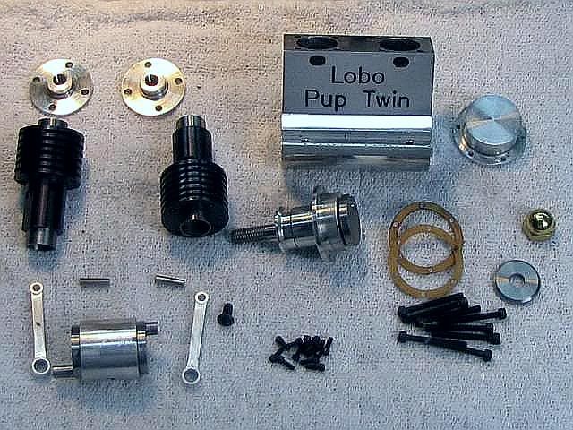
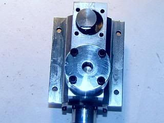
All the precision fit parts are done, although there will be some fiddly little parts in the fuel system.

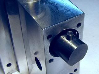
Continuing upward, the cylinder heads are next. They are mostly a straight turning job, and since all the top end sealing is done by the contra piston they don't even need to be gas tight.

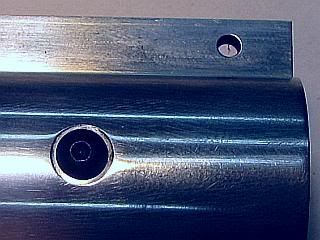
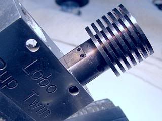
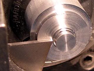
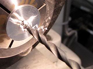
Started off with one inch diameter 6061 aluminum bar stock in the lathe. Turned the three diameters down and then cleaned out the tool tip radius where the meets the cylinder so the head would seat on the top of the cylinder. A 0.005 or 0.010 chamfer on the top of the cylinder would have eased this requirement some.

Head1.jpg
Head2.jpg


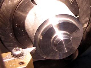
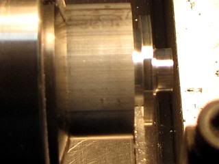
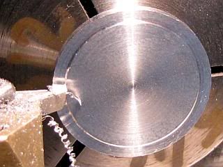
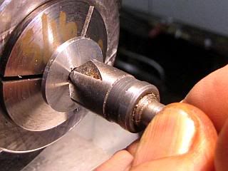
Head is cut off, leaving a few thou for cleanup to thickness, and everything repeated for the second head. Then the head is reversed in the lathe and the top is faced off bringing the head to the finished thickness.

Head3.jpg
Head4.jpg


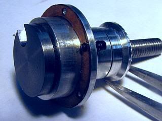
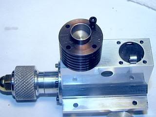
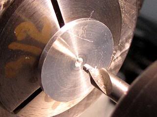
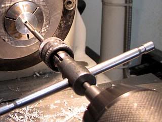
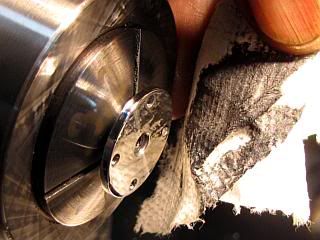
Center drill, drill, tap 10-32 and knock off the burr with a hand held countersink.

Head5.jpg
Head6.jpg


Head7.jpg
Head8.jpg


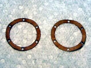
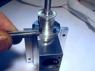
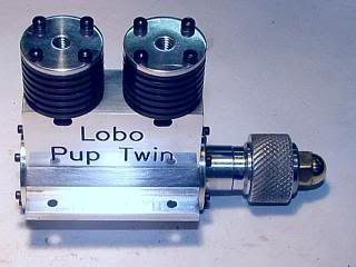
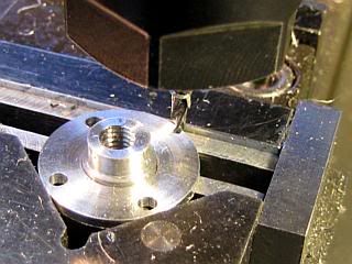
After indicating the head to locate the center, the mounting holes were coordinate drilled on the milling machine. I did not center drill, but mounted the drill in a ER collet with only about 1/2 inch protruding. This is stiff enough when drilling aluminum that no center drilling is needed. Both sides of the holes were deburred with a small hand held countersink, then back to the lathe where a slight chamfer was put on the outside edge with a file and the part sanded with 800 and 1200 grit abrasive paper and hit with just a little bit of metal polish. The chamfer has to be small to keep it from going under the mounting screw heads.

Head9.jpg
Head10.jpg


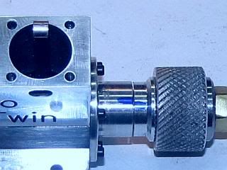
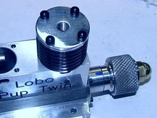
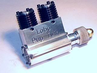
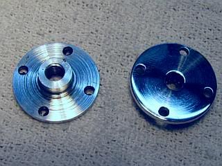
And a finished pair of heads.
Gail in NM

Head11.jpg

 
Gail, I noticed you are using indexable tooling. I finally bit the bullet and ordered a decent set of indexable turning tools. Mind you, I have a basic import 1/2" set for TCMT 3252 inserts. What kind of tools are you using? I ordered a set of 1/2" tools for CCMT 21 and DCMT 21. I was thinking about getting some for VBMT inserts, but don't know if I'll need them. They do offer some visibility in the small parts.

Oh, one more thing are you using separate inserts for aluminum or just one type for everything?

The engine looks great!
 
Greg (dieselpilot),
Since I mostly build small toys, I use small VBMT inserts for most of my turning. For my general purpose use, I use VBMT 2 1.5 1 C2. This is 1/4 inch inscribed circle insert with a 1/64 tip radius for cast iron and non ferrous materials. I use it for 12L14 and 1144 steel, but will switch to C6 grade if I am cutting tougher steel. That is rare for me. In 12L14 I can reduce the diameter by 1/4 inch per pass without problems. See photo in the PMC IMP thread of reducing a crankshaft.
http://www.homemodelenginemachinist.com/index.php?topic=4422.msg47759#msg47759

My insert holders are brass that I made up. They have a 2 degree negative lead, that is the tip points toward the headstock by 2 degrees. This makes for a nice facing cut from the center of the stock outwards. It is very important that the inserts are are on center line if you are doing small diameter work. I have a dial indicator stand made up just for that purpose.

I buy generic inserts from carbidedepot.com. They are about $2 each, but come in boxes of 10. Carbide depot has given me very good service on both inserts and carbide end mills.


Not a lot has gotten done on the Lobo. I cut the gaskets. No photos, you know what gaskets look like. After sanding out most of the machining marks, I decided to engrave the crankcase. After polishing, I will fill the engraving with black Lacquer-stik. Don't expect too much in the way of polishing. Once I have the machining marks out, I generally just give things a quick rub with some polishing compound. Polishing is not something I enjoy. Besides, when I finish an engine and get it running I am ready for the next project.

Crankcase29.jpg
Crankcase30.jpg


Gail in NM


Gail,

I haven't built up a like for polishing either...though I do like the end result and know it's a necessary chore.

As for your statement about 'you all know what gaskets look like'...I wouldn't be too sure. I think I do...finally...maybe. But only because I've lived long enough to come across them. I'd be surprised if my kids know what they are.

I liked the 'title plate'...I've been thinking about trying to come up with a logo or something that I can apply to my models (once I'm proud enough of them to show outside the family or to this forgiving and understanding forum ;D.)
 
Zee,
I had a logo plate made at a trophy shop $5

IMG_0441.jpg


The only way you do what Gail did is CNC

Tony
 
Tony,
You are half right. I did use the CNC to do the engraving, but it is not the only way to do it. Many years ago I made a pantograph engraver. Made the fonts for it a bit at a time as I needed characters using it and tracing large letters. Later I got a good buy on a commercial engraving machine with a couple of sets of fonts and had it for a long time. I sold it after I got set up for CNC.

I like the laser engraved plate on your engine, but I don't think the finish would take kindly to the ether in the model engine fuel. I have used them on some steam stuff. How did you mark the serial number and build date on your plate. It does not appear to be laser engraved in the photo.

Zee,
Just for you ;D I will throw a photo of the gaskets in my next post. I have been beginning to think that I have been putting more photos in that people will want to see. I just checked my folder on them and it appears that I have 181 photos in this thread. There will be at least 40 or 50 more before it is finished. I have kept them small so they don't take too long to load. Not everyone has a high speed connection.
Gail in NM
 
Hi Gail,
That's a question for the trophy shop but they look stamped. I coated the plate with clear polyU before I mounted it. So hopefully that will protect it.
Tony
 
I'm back.
Sorry about not being around this thread for a few weeks. The doctors decided that I needed a tuneup and so I have not been able to do much model engineering.

The Lobo Pup is about ready for the final assembly of the bottom end. A bit of cleaning of parts and I will start from the bottom up and stop at the compression screws and compression limiters. I need that much assembled to be able to measure and make the limiters. After that the final parts will be the fuel system.

I should be able to start publishing the assembly photos late this week, but in the meantime, just for Zee, here is a photo of the gaskets.

Gail in NM

Gasket.jpg
 
Glad to see you back at it, Gail. Hope all is well! Looking forward to another runner.

Dean
 
Thanks Dean. Glad to be back at it.

Here are the parts needed for from the bottom of the crankcase to the top of the cylinder head except for the fuel parts. Had to lay them out to refresh my memory. Crankcase has been polished and the lettering filled in with black Lacquer-Stik since the last photo of it.

The screws are:
12 ea 0-80 x 3/16 Socket head cap screws (1/4 inch long would also work)
8 ea 2-56 x 3/4 Socket head cap screws (7/8 would be ideal, but 3/4 should be OK. Don't have any 7/8)
1 ea 4-40 x 1/4 Button head screw. Pan head would work but I like the looks of the button head

Gail in NM

PartsLower.jpg
 
Good to see the engine coming together! Hope its up and running soon! ;D

Anthony


Glad your back. Hope its nothing to serious. Great job on the engine.

Ron
 
Glad to hear you are back in the shop!

Those is some seriously shiiiinyyyy metal parts!! ;D Very nice!
 
Hi Gail,
I was wondering what happened to you. I'm in the same situation, was sick and now starting to fell better. Can't wait to see the shop again. Feel better and I'm hoping to see that little baby purr some!
Tony
 
Glad to see you back to it Gail.

And the collection of parts looks very nice indeed. While following a build, one does not often get an "overall" feel, so thank you for putting those together!

Kind regards, Arnold
 
Thanks for the comments and the welcome backs from everyone.

It's time to start sticking parts together and make it start to look like an engine.

Starting at the bottom, the first job was to install the center bearing with the rear crankshaft and put the connecting rods on at the same time. It is assembled from the rear of the engine. Since everything is symetrical it can be assembled with the exhaust on either the left or right side as desired. The fuel system will of course be on the the other side. This also means that the engine will run equally well (I hope) in either direction. I chose to put the exhaust on the right side as this is the most common position for model aircraft engines.

Parts for this phase in first photo. Second photo shows the center bearing starting to be slid into place. The front connecting rod needs to be installed before it gets slid all the way in because of the extended crankpin. The rear connecting rod can be installed later.

Assy1.jpg
Assy2.jpg


Using the installation tool, the center bearing assembly is rotated and positioned so the 4-40 screw can be inserted to retain it.

Assy3.jpg
Assy4.jpg


A gasket is placed on the front crankshaft assembly. I put a single 0-80 screw through it to keep it in position while installing it in the crankcase. The front crankshaft has to be rotated so the slot engages the crankpin on the rear crankshaft. Then the rest of the screws are added. The gaskets are not really necessary if the machined surfaces mate well, but I like them. The drawings are dimensioned so the engine can be built either with or without 0.006 inch thick gaskets with no changes necessary.

Assy5.jpg
Assy6.jpg


Gail in NM


Before starting the assembly, I should have mentioned the lubrication of the parts as the engine is assembled. I use a light machine oil for everything. As soon as the engine is run for a short period the oil in the fuel will replace all of it. Both ends of the connecting rods get a drop of oil during assembly. The cylinder, piston and contra-piston only get a thin film of oil wiped on. Any excess oil on these parts will make setting the initial compression difficult during assembly. For the cylinder I use a cotton swab with a small amount of oil on it to both clean and lube the cylinder.

Continuing on with assembly. In the next photo notice that I have installed a 3/4 inch diameter knurled knob on the prop shaft. While not necessary for the immediate assembly operations, it is convenient and something to increase leverage on the shaft will be necessary when setting the contra-piston later. The engine will get turned over a lot during assembly as it is important to check for free operation after installing each part.

Each set of cylinder parts are installed at one time to avoid the possibility of mixing up the pistons and contra-pistons for the cylinder.

First the crankshaft is rotated so the front connecting rod is at top dead center. One of the considerations during design was that the small end of the connecting rod would be slightly above the top of the crankcase so the piston and wristpin could be installed. Then the piston is slid over the connecting rod and the wristpin is installed. Note that the transfer notch on both pistons face the center of the crankcase. You have to look close in this photo to see the notch, but it shows up well in a later photo of the rear piston.

Assy7.jpg
Assy8.jpg


Then the cylinder is slid over the piston and rotated so the transfer passage is facing the center of the crankcase. Then it is seated on the crankcase using at least one bolt to align it. The contra piston is then pressed into the cylinder. I left it only part way in the cylinder for the photo, but I pressed down almost flush with the top of the cylinder. You can also see that I had the rear connecting rod installed in this photo, but it could be installed later.

Assy9.jpg
Assy10.jpg


The cylinder head is installed using the 2-56 x 3/4 screws and the screws tightened. Good time to check that everything is free by turning the engine over. It will take a firm grip on the knurled knob to get past top dead center. Everything is repeated for the second cylinder, making sure the transfer notch on the piston and the transfer passage on the cylinder face the center of the crankcase.

Assy11.jpg
Assy12.jpg


The rear cover is installed with a gasket the same as the front bearing.
And it is starting to look a little bit like an engine.

Assy13.jpg
Assy14.jpg


Gail in NM
 
Gail this is the first time I saw this engine. I am amazed at the skill of the people on this site like yourself. You do beautiful work. Jack
 

Latest posts

Back
Top