Kog 5 (Radial Engine Project)

Home Model Engine Machinist Forum

Help Support Home Model Engine Machinist Forum:

This site may earn a commission from merchant affiliate links, including eBay, Amazon, and others.

SKmetal7

Member
Joined
Sep 30, 2011
Messages
19
Reaction score
8
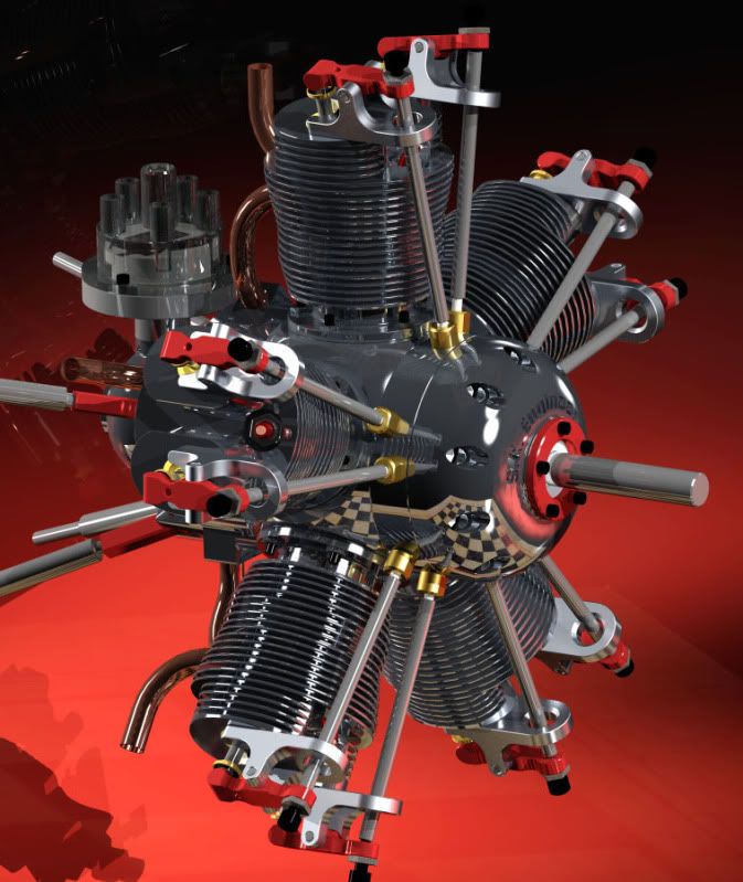
Ok guys. So after the help I got over at the CNCzone and here (mostly here) (thanks Steve and Peter!) about master connecting rod design, I decided to continue designing my 5 cylinder radial. It's a long term project, might be moving soon, and I want to go back to school (mechanical engineering). So I don't know how long until I start making chips; but I DO want to actually build this!

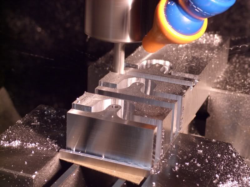
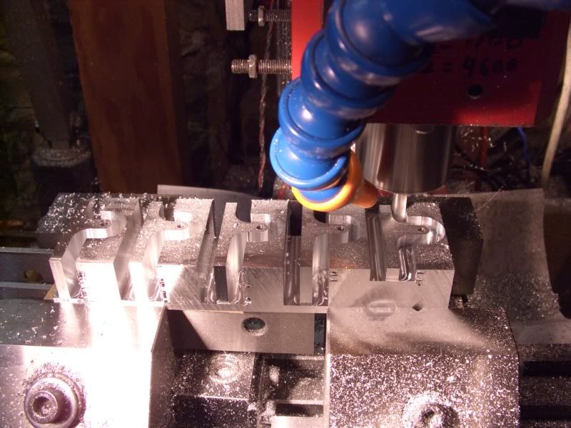
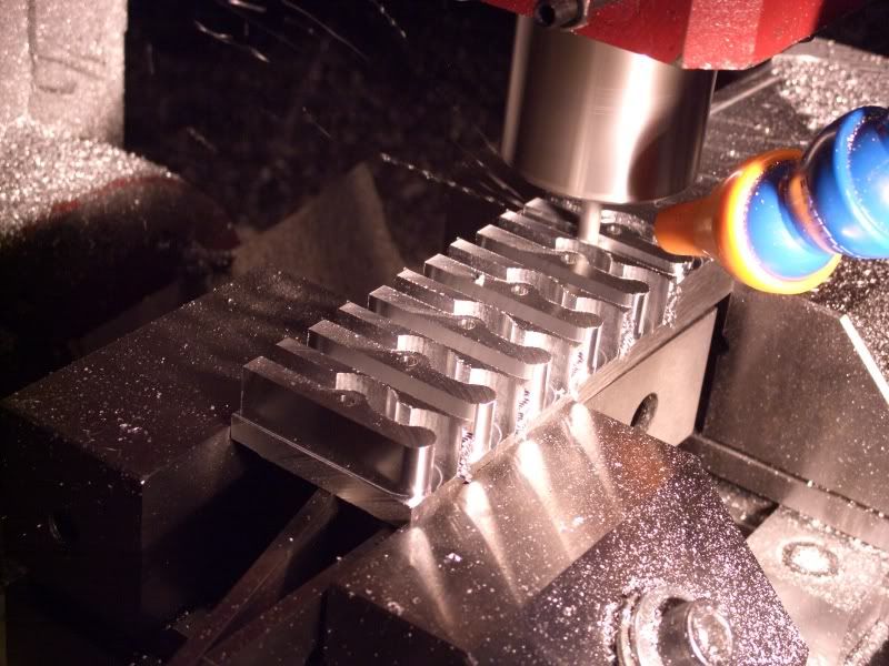
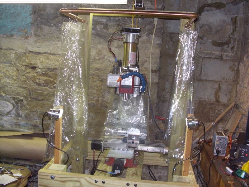
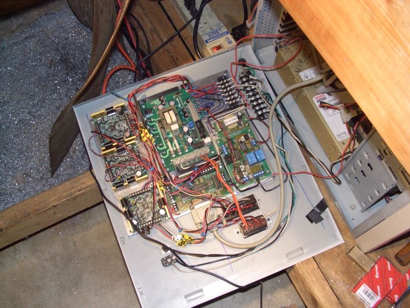
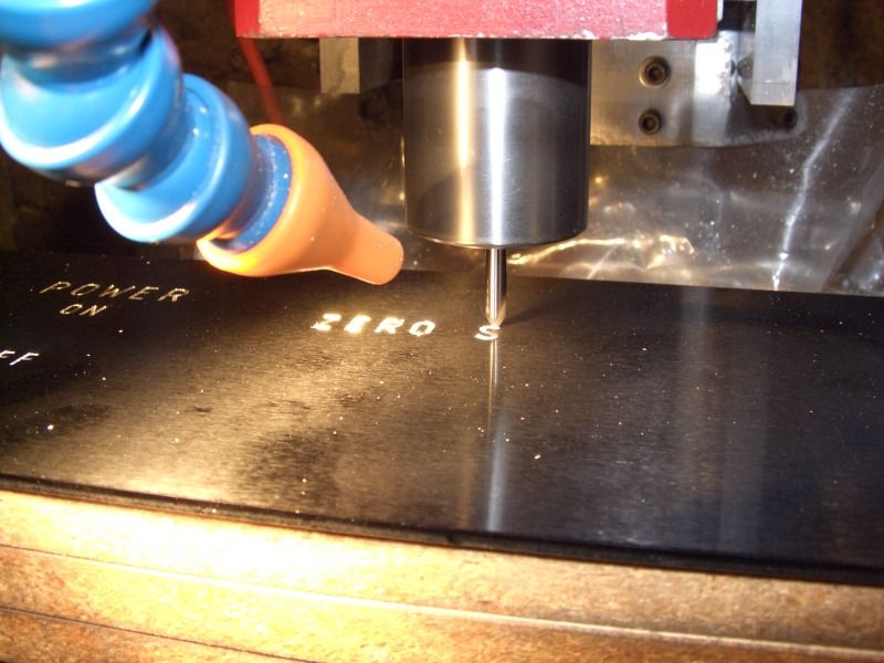
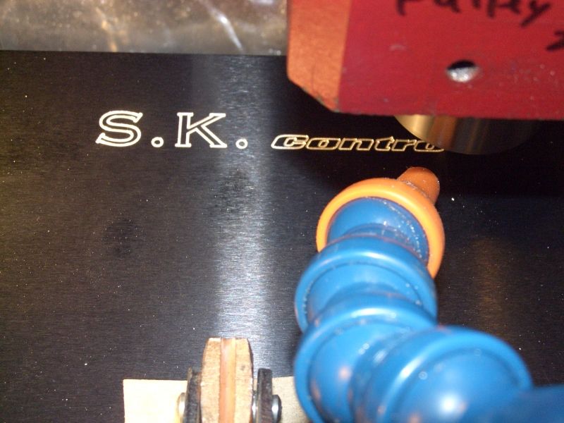
A little background: I'm a 24 year old engineering student, been out of school for 4 years after having attended college for 2.5 years after high school. Trying to return and finish my degree. In the mean time I practice cnc machining and CAD design, as a hobby and to further my skills. Been machining since I acquired a lathe and mill from Harbor Freight back in 2006, CNC'd the mill and can't stop designing/ cutting since!! Truly addicting feeling when something comes out of a block of aluminum that you designed in CAD (and it actually fits/works). Have designed and built a couple compressed air motors, and a gas engine(which I still need to get running) over the past year (I'll post pics of those later); so I have some experience.

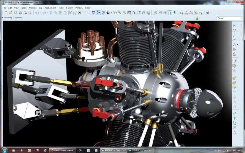
This project is the most complex and intricate I have done so far. I have learned much about Pro/Engineer CAD software since I started this project on September 19, 2011 (official start date); but have used the program since 2006. I have designed about 90% of the engine in CAD. My CAD program is about 6 years old, and not meant for Windows 7 so it's temperamental and likes to crash, but I some how got this far. I still need to figure out a distributor, mounting scheme, and if I should have an internal oil pump, along with about a million small details.

A few questions:
1. What is a good compression ratio? 8:1, 9:1?
2. Should I worry about having the ignition timing advance at higher RPMs? Probably not a big deal.
3. What's the best method for having equal compression ratios in each cylinder? I was thinking of using longer cylinders for cylinders 2, 5, and 3,4. I'd hate to have different piston lengths; but it could work, I wouldn't have to have different pushrod, intake tube lengths.

Material selection:
Crank/ main shaft: 1144 stress proof. Easy to machine, doesn't warp, strong.
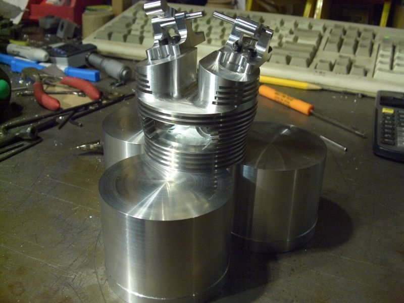
Heads/ cylinders/ crank case: 6061 Al. Light, cheap, easy to machine.
Rockers/ rocker arms/ pistons: 7075 or Fortal AL. Strong, easy to machine, have lots of Fortal laying around.
Cylinder Liners: 4130 Steel tube. Don't want to bore out a lot of steel so I want to use some kind of tube, strong.
Pushrods: Titanium. Just because! ;D
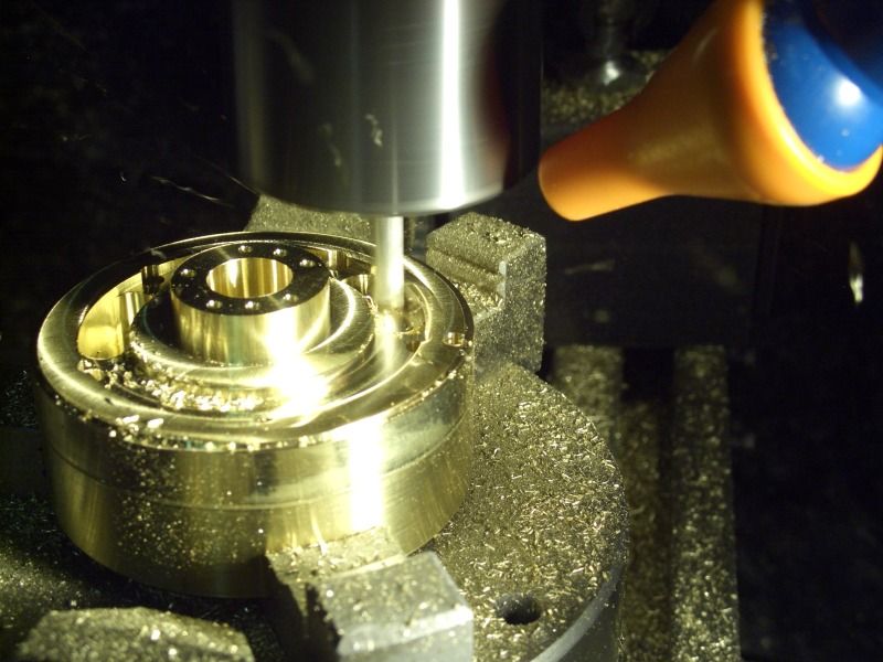
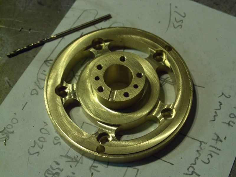
Main Bearing: Brass or Bearing Bronze. Expensive either way, but I don't want to use aluminum.
Valves: ??? maybe 1144.
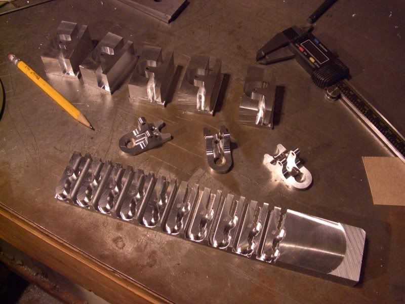
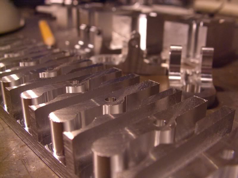
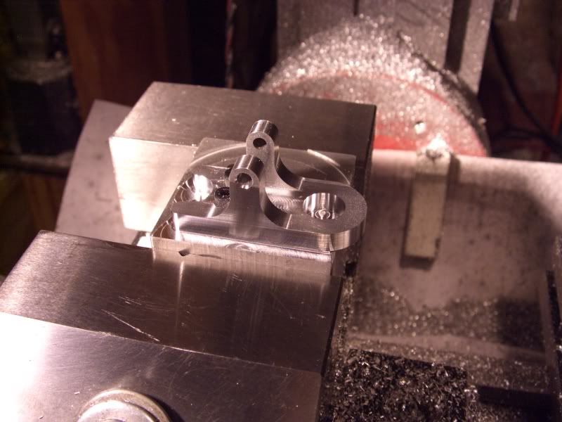
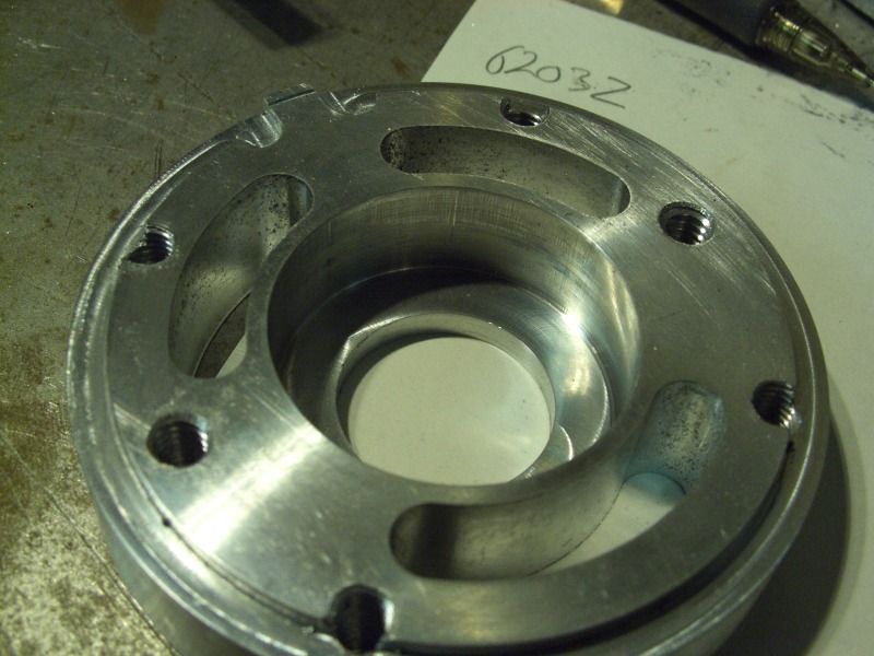
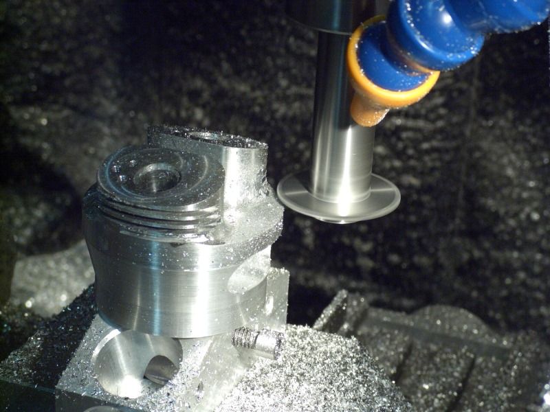
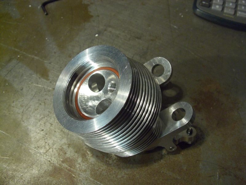
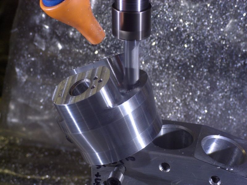
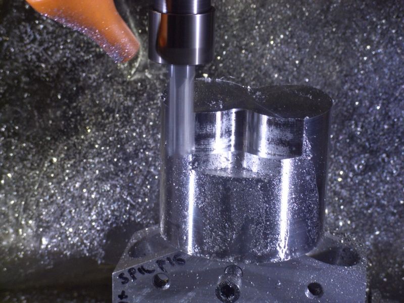
Ok now I'll post some vids/pics:

[ame]http://www.youtube.com/watch?v=-G0XYRx2O98[/ame]
[ame]http://www.youtube.com/watch?v=jY5ZzxdQXsY[/ame]
[ame]http://www.youtube.com/watch?v=BE6FhgO3u2Q[/ame]

closeup2.jpg


engine cut 3 oct 9.jpg


engine cut 2 oct 9.jpg


engine cut 1 oct 9.jpg
 
Hey SK,

I would think that if you get your pistons balanced....ie all the same weight....your compression ratio should fall right into place.

Dave
 
SKmetal7 said:
A few questions:
1. What is a good compression ratio? 8:1, 9:1?
2. Should I worry about having the ignition timing advance at higher RPMs? Probably not a big deal.
3. What's the best method for having equal compression ratios in each cylinder? I was thinking of using longer cylinders for cylinders 2, 5, and 3,4. I'd hate to have different piston lengths; but it could work, I wouldn't have to have different pushrod, intake tube lengths.

Wow, another promising looking 5-cyl radial design & hopefully subsequent 'build'. I similarly decided to take a (longish) side road departure to learn 3D cad. I dont have an engine or plans to show quite yet, but slow-but-sure at least a picture is coming together. I'll have lots of dumb, newbie questions for the pro's here shortly when it comes to actually 'making' the thing. Cad pipe dreams are one thing, finished metal parts & succesful Vroom is another! ;D

Anyway...smarter people than me can better answer, but here goes
1) I assume because you mention ignition advance you are contemplating gasoline/spark ignition (vs methanol/glow)? In Malcom Stride's book (Miniature Internal Combustion Engines) he mentions CR glow = 10:1 or higher. Spark = 5:1 - 6:1 but he personally recommends 8:1-9:1. I think the Hodgeson 9-cyl radial quotes 6.7:1. Then on the higher range is the 1/4 scale Offy at 9.5:1. Once upon a time I put a bunch of popular SIC engine CR's into a table, but its MIA.
2) completely out of my league

3) This post which discusses the the master rod layout speaks to this issue.

http://www.homemodelenginemachinist.com/index.php?topic=15976.0

From what I can tell, if you lay out the link rod pins on the MR with compensation angles as described, you can then manufacture identical link rods, pistons, cylinder jugs & heads and they will have identical TDC geometry, therefore CR. If this assumption is wrong for whatever reason, please, someone tell me... SOON! If OTOH you elect to lay out the LR's on the MR by equal angle phasing (360 deg / 5 cyl = 72 deg) then you will not have equal CR & require some form other fix that alters the TDC volume (modified cylinder, piston, head shim, LR geometry...). Some people have commented that this isn't necessarily a big deal & dont worry abbout it. And Ive seen plans for what appear as succesful engines with equal phasing. But I guess I would take that comment one step further and ask:

- what stroke are we talking about? In my case (a large-ish stroke) I noticed uncompensated CR gets out of whack among cylinders moreso than than I felt comfortable with. I seem to recall a target CR of say 10:1 could be as low as 8 on another cyclinder. On methanol/glow that presents a completely different running condition & I was concerned that the bottom cylinders might be hampered. On a lower, more moderate stroke design, I think the CR's work out closer to one another. By how much you would have to calculate or determine.

- what fuel/ignition system? Again, outside my league, but maybe gasoline & ignition are more forgiving of varying CR or can access other tricks? In the methanol/glow world, all you can do is mess with shims or glow plug heat rating. It just seemed easier to strive for equal CR as much as possible from the outset.


I'll try to explain how I heard it described -

Oh - And it is much easier to do using CAD
(this is for 5 cylinders...)

Start out with Piston 1 and get the master rod length correct for the compression ratio you want. Now rotate the crankshaft 72 degrees and reposition the master rod and piston to be in the proper position. now place a piston and slave rod for TDC and draw the pin hole for that rod. Repeat for cylinder #3. For cylinders 4 & 5 you can mirror the pin holes for cylinder 2 & 3, just make sure you mirror them on the master rod center line. I am fairly certain that this is similar to the way theylayed out the early ones, just did it with a few paper pieces on the drafting table.
 
I'm going to use gas/ spark for fuel/ ignition. The compression ratio will be between 8 and 9 to 1. ~1% shouldn't make much of a difference in a model engine. This way I won't have to make different cylinder lengths. Its between the recommended CRs for these engines anyway.

To get the master rod and link rods the correct length, along with TDC, I'm using this method in this post: http://www.homemodelenginemachinist.com/index.php?topic=15976.0 Seems to work pretty well. The BDC is a little off, but not too much to be a concern. The engine might "pop" a little when the exhaust valves open on the lower cylinders.

I'm trying to decide whether I want to build an oil pump off the crank... I don't know how I'd fit it. It would have to be behind the impeller, and I don't know how I'd route the oil passages. Would the link rods need to have a passage in them? I'd have a groove in the crank pin, and then a hole drilled in the master con rod to the wrist pin, but the link rods would be tricky to have that. And how is oil scavenged? I'd think that oil would just build up in the lower cylinders....

Lost of questions!!


render2.jpg
 
SKmetal7 said:
... The BDC is a little off, but not too much to be a concern.

... I'm trying to decide whether I want to build an oil pump off the crank...

#1) I think that is the uncontrollable 'by-product' of equal TDC; the BDC's are at slightly different positions relative to a common sleeve geometry. I dont know that it would be a problem though, or at least be a preferred tradedeoff to having equal & balanced TDC's (C.R.'s) etc

#2) Can't help you much there aside from suggesting 2 designs:
- the Edwards 5-cyl radial, public domain design: (methanol fuel, glow plugs, oil pump)
- the Kinner 1/4 scale 5-cyl, SIC design: (gasoline fuel, spark ignition, oil pump)

.. plus some other forthcoming designs recently announced on this forum!
 
Ok I've started to make some parts! I started with the rocker brackets, and rocker arms. I started with these since they are set in stone and will not change; and it was a good motivator part, something easy I could crank out many of.

I made them out of Fortal Al. Very strong and hard stuff, yet light weight. Machines very easily with sharp carbide endmills. In the photos I'm using an SGS carbide 1/4". Nested the parts for quick machining. Took ~55 mins for one set of 5 rocker brackets, and 1hr 12mins for the 10 rocker arms. The first set went fine until the last bracket. I didn't realize that the vise on the right was a little higher than the left vise. Sooooo on the last pass my end mill ate vise, the steppers lost steps and then .75" of endmill crashed into the material. Amazinly the end mill didn't break or even chip! But it did throw my mill out of tram and the last part turned out tapered. It's a lot duller now, luckily I had another on hand. Still need to do the final operations on most of the parts; but it's looking good so far.


I also want to anodize some of the parts, like the arms and other high wear components. I have been reading some articles on the process, but I'm not sure of some of the chemicals involved. Can I use battery acid from the local auto parts store, since that's ~30% sulfuric acid? And I'm not sure on how to seal the parts after anodizing.

render12_1.jpg


CIMG4268.jpg


CIMG4272.jpg


CIMG4280.jpg


CIMG4282.jpg


CIMG4289.jpg


CIMG4291.jpg


Wooo. Been a while, but I have been steadily working on this engine. Many CAD hours, and still have CAM programming to do.

I started the cam/ main bearing and cylinder heads, then decided to upgrade my mill. I redid the z-axis on my HF mini mill to make it more solid, bought a treadmill motor (1.5 hp) and made a new face mount, rebuilt my CNC control box, and recently rebuilt my mill bench with integrated shower curtain! Along with computer crashing problems I had to sort out. Not fun when your working in CAD and computer decides its too tired. Lots of work; but I can now continue work on the engine. LOTS OF PICS!

CIMG4640.jpg

CIMG4643.jpg

CIMG4673.jpg

CIMG4682.jpg

CIMG4706.jpg

CIMG4717.jpg

CIMG4725.jpg

old mill:
CIMG4623.jpg

new bench:
CIMG5158.jpg

CIMG5153.jpg

new controller:
CIMG4791.jpg

CIMG4815.jpg

CIMG4823.jpg

CIMG4883.jpg

CIMG4936.jpg

CIMG4961.jpg

CIMG4963-1.jpg

CIMG4970.jpg

engine parts:
CIMG4551.jpg

CIMG4555.jpg

CIMG4561.jpg

CIMG4564.jpg

CIMG4478.jpg

CIMG4498.jpg

CIMG4442.jpg

CIMG4454.jpg

CIMG4427.jpg

CIMG4429.jpg

CIMG4404.jpg

CIMG4412.jpg

CIMG4419.jpg

render15-1.jpg

CIMG4607.jpg

CIMG4572.jpg

CIMG4593.jpg

CIMG5170.jpg

CIMG5179.jpg


I'll be done with the heads, probably tonight. Then I'll start on the cylinders... I'm not sure. Still need to buy more material.
 
SK Great setup you got there. Thanks for the nice clear pictures. Welcome to the forum and we look forward to following your progress
 

Beautiful job on your models and machining. Your parts look great.

Is there anything still stock on your mini-mill. It looks pretty beefy!

 
Thanks, guys! The mill is beefy, but the x-y table is stock and has some play in the dovetails, so it does chatter a bit when I push it.

I have a question on the springs to use for the valves. What is a good spring rate for valves this size? (3/16 shaft diameter .45" valve diameter, .1" travel.) I found some that are 37lbs/in and compressed would give me ~10lbs of sealing force.
 
SKmetal7,

these Parts are stunning to look at, great work so far!
Many details of your work look well designed, but about a few of them I'm concerned about their dimensions.
Especially the crankshaft looks very thin - what about the stiffness of this part?
I'm in construction of a 9cyl. radial for my Gee Bee Z Airplane, there I realized it's not easy to find a crankshaft that you 'like' (machining, weight, bearings, pinion for the cam-disc-gear), but the strains on it just require a relatively strong part.

Your solution with the screwed-to-the-cylinder cylinderhead is a very nice idea, I wish I could do the same on my engine.

Christian
 
The crank shaft should be strong enough, it's 7/16" stressproof 1144 steel. I can't really design a larger diameter shaft because of the cam gearing. I'm already at the maximum internal bore of the gear already.

I'd like to see that 9 cylinder your designing. ;)
 
Back a few you asked about anodizing and battery acid. I tried to anodize a couple parts and had reasonable luck using swimming pool acid instead of battery acid. Its much safer to work with- it wont rust every tool in the shop like battery acid. It was less than $10 for enough to make 2 batches of about 1 gal .

I believe I read about it on this forum, but right now I dont have a link.

Nice work on the parts and the mill.
 
I can't really design a larger diameter shaft because of the cam gearing

Thats the challange I was also confronted with.
I found a good solution by changing from the common internal ring gear (2 stages) to a cam gear of 3 stages. The advantages of this gear were a larger-diameter pinion on the crankshaft, and a much cheaper gear itself. The price of these advantages is, that the camgear requires a little more space.

By using this layout, i was able to give the crankshaft a diameter of almost 11/16" at the cam-gear pinions seat.
The strength of the crankshaft was never a problem, but a sufficient stiffness made this large diameter necessary.

I added 2 photos oh the gear-parts. Nothing spectacular, but narrow tolerances.

The engine will have a displacement of 125cm³ - 7,6 cu. inches.
I can add a post of the other parts as soon theres something interesting to show - at the moment I'm buisy with restoring some new (old) machines, this will still take some month of work.


100_7927.JPG


100_7931.JPG
 
CF, those gears look great! Did you cut them yourself?

Well It's been a while since I've updated and the new site looks spiffy!

Made a lot of progress.

CIMG5149.jpg


CIMG5188.jpg


CIMG5193.jpg


CIMG5208.jpg


CIMG5279.jpg


CIMG5288.jpg


CIMG5295.jpg


CIMG5303.jpg


CIMG5309.jpg


CIMG5317.jpg


CIMG5358.jpg


CIMG5365.jpg
 
Last edited:
The surface finish on the impeller is a bit rough. I'll probably try sandblasting it smooth.

The pictures include making the rear sections of the engine, and the valve and lifter bushings.

CIMG5472.jpg


rear section model.jpg


rear section model 2.jpg


CIMG5500.jpg


CIMG5504.jpg


CIMG5506.jpg


CIMG5512.jpg


CIMG5513.jpg


CIMG5518.jpg


CIMG5524.jpg


CIMG5561.jpg


CIMG5564.jpg


CIMG5575.jpg


CIMG5576.jpg


CIMG5579.jpg
 

Latest posts

Back
Top