Kerzel's V2 CO2 engine

Home Model Engine Machinist Forum

Help Support Home Model Engine Machinist Forum:

This site may earn a commission from merchant affiliate links, including eBay, Amazon, and others.
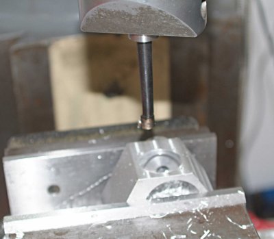
My new boring bar came from Enco today, so I was able to make some progress, boring the holes in the crankcase for the cylinders:

medium.jpg


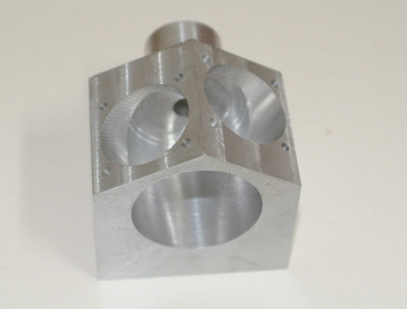
In setting it up in the vise I found that one of the faces was off by a degree or so. I wonder if it slipped when milling the angle?? It's not too critical and probably not visible without close inspection, but irritating to me.

Here's the crankcase with both holes bored:

large.jpg


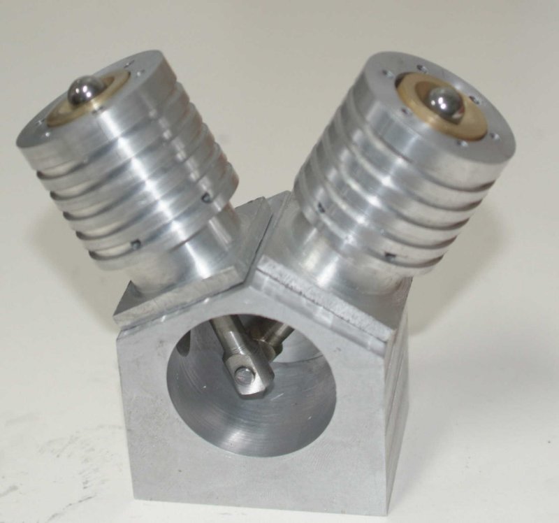
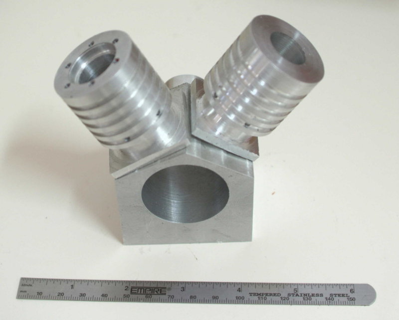
And with a preliminary test fit to get an idea of how it will look:

large.jpg

 
Very nice, It always amazes me the small scale some of you work in.
 
After overboring the second cylinder I decided to make a new piston to fit. I had a 2" piece of 1" dia brass round that I turned down to the bore diameter, parted off, and machined much as I did the other steel piston.

After dinner I made a couple of wrist pins from 3/16" drill rod and pressed them through the piston and rods. A test fit onto the crank pin looks OK. I still need to clearance the piston rod from the bottom of the cylinder as it binds when the crank is at the top.

Yesterday I glued the crankshaft bushings into the block with locktite, so the assembly is starting to come together. I did discover that I will need a separate base as the weight of the steel flywheel is enough to tip the rest.

I still need to find a couple of steel balls for the valves. I will likely need 3/8" balls. There's a seller on eBay that has a wide variety of balls in fairly small quantities.
 
I found some steel balls at the local Ace harware store. Drilled and chamfered the valve seat and put the pieces together for a poser shot. I need to drill the air inlets on the cylinder heads and the pins on the pistons, and it will be ready for a test.

110621867large.jpg
 
kvom,

Looking very good :bow:

Best Regards
Bob
 
Yesterday I bored/drilled one of the cylinder heads. For the air inlet I will thread it 1/4-20 and fabricate a screw-in attachment so that the air feed can be removed from the head. I also threaded the hole for the pin in the top of the piston 5-40. To determine the length of the pin needed I used a 5-40 SHCS and shortened it until the ball ceased to hit the top of the head. So I will cut and thread a piece of 1/8" drill rod the same length as the screw.

I also got the second piston to have a good fit with the cylinder by lapping with toothpaste. At first it was too tight to turn the crankshaft by hand. So I clamped the crankcase in the vise and clamped the crankshaft with a 5C collet in a collet block. Then I was able to turn it by hand holding the collet block. "Booty fab!" After a few minutes of this with the toothpaste it was turning pretty freely. I took off the collet and ran it for about 30 seconds with the electric drill. It now turns easily by hand.

A few more small parts and I can try to run it on one cylinder.


i started to make this engine but it made me mad cause it was so small . put it in a box until i could get the patience to finish it. I'm watching this build with intrest so maybe your build will reinspire me. great job. thank you for showing your build
 
I cobbled together everything needed to mount one of the cylinders. The air inlet I made is too small to clamp securely with the plastic feed tube, so that will need to be redone.

I applied compressed air anyway and found that it became very hard to turn the flywheel, indicating that the cylinder bore was pressurized. Since the cross sectional area is .44 square inches, 60 PSI air means a resistance of 26.5 pounnds. Of course this is good news and bad news. The good news is that the piston/cylinder bore is relatively air tight. The bad news is that I should not get pressurized air into the cylinder bore until the ball valve lifts, so I have a leak between the cylinder head and the bore. Either the ball is not seated properly or the valve seat is not seated closely enough in the cylinder.

So the next step is to make a more secure inlet tube and also to lap the valve seat both to the cylinder and to the ball.
 
When I made my Co2 engine, I made a test fixture for the ball seats. It's a simple mock up of the block and head to apply air and listen. The ball can be poked off the seat with a piece of rod from the bottom.

You might give it a try.

Also remember that with a tight piston, when moving toward top dead center, the piston will compress air until the ball is lifted. This compression will need to be overcome with higher air pressure. My engine needed 65lbs to sustain a run.


DSCN1080.JPG


DSCN1081.JPG
 
Made some more "progress" this afternoon. First I needed to fab an inlet tube that would sustain higher pressure without blowing off the tube. From a piece of 1/2" brass rod I turned one end down and threaded it 1/4-20 to match the threaded hole in the head. The other end I turned to .325 and used the compound to cut three tapered barbs. This turns out to work well with the hose clamp. I still have some leakage around the threads as they are not tapered, but that's OK for now.

I lapped the valve seat a bit with toothpaste and hooked it all up, but there is still high pressure air bleeding into the cylinder. I'm not sure if it's around the ball or the perimeter of the seat or both. If I can't get it to seal I think I will bore out the top of the cylinder to make a wider rim for the seat, and make a new seat to fit.

I took the cylinder off the crankcase and will use it in a manner similar to Steve's test rig, hoipefully. I also tok the crankshaft off and will cut a flat for the flywheel setscrew.
 
kvom,

Did you give the balls a light tap with a soft dolly and hammer? This helps to bed them properly to the seat.

Hope this helps.

Best Regards
Bob.
 
Sounds like something to try, Bob. Thanks.

I made a number of tries with the cylinder+ head only. I put a bit of way oil in the bore, which had it easy to see where air was leaking around the ball. Tried lapping a few times, and then decided to try the other valve seat

I polished it with steel wool as well as some toothpaste lapping. Then I butoned it up, and seemed to have it air tight. So I put in the piston and screwed the cylinder onto the crankcase. I turn on the air and don't hear leaking from the cylinder. Tried to start it by turning the flywheel, but then I get loud air leak noise. Off with the air, then back on, and all is quiet. So now I'm guessing that the ball is deformed or scratched and seals in one position but not others. Took a break.

Next time out in the shop I'll try it with another ball, and will try the tap-to-seat method as well.

 
Still frustrated today. I tried Bob's idea of tapping the ball into the seat with a plastic hammer, but no go. The cylinder is air-tight when air is first applied, but once the ball lifts the first time it ceases to be, as if the ball doesn't reseat. I did notice when experimenting with just the cylinder and head, that when the cylinder is inverted and air is applied, the ball doesn't seat. Rather it spins around the inverted cone at a high rate. I think this is what might be happening.

One thought: in Kerzel's build he used a center drill to make the valve seat, meaning a 60-degree countersink. I used a 90-degree countersink since I needed a larger hole. I wonder if the angle is too shallow. If so, I should be able to make a seat with a steeper angle using a boring bar and the compound.

I decided to take a break and start the rebuild on my bandsaw until the frustration recedes. :'(
 
I did some calculations today preparatory to making a new valve seat. My conclusion is that the 3/8" ball is probably too big. If anyone cares to comment on these calculations please feel free.

The original version uses a 3/32" ball. Ignoring the difference due to the taper, the ball has an effective area of .007 square inches, and at 60 psi would be held by .414 pounds of force. My 3/8" ball would have an area 16 times greater and hence a force of 6.6 pounds. To maintain rotation, the flywheel would need sufficient angular momentum to deliver this kind of force.

I measured the motion of the piston as well. At the point where the piston closes the exhaust holes, the depth from the top of the cylinder is 1.144 inches. When the lift pin clears the bottom of the seat the depth is .556 inches. This gives a ratio of about 2, a bit less than Kerzel's figure of 2.5. This means that the cylinder bore would be pressurized at 28 psi, and hence the engine ought to run at 30 psi or so.

My conclusion is that I am going to cut the seat at 60 degrees to hopefully enable a better seal, and try smaller ball(s).
 
If you scaled up 2X then I would try a ball 2X and not 4X the size of the original. A #3 center drill is close to 2X the size of a #1. The lift on the ball is critical. .010 - .015 is the range.

If it were me, I would try the following first.

.1875 (3/16) ball
#3 center drill
.020 - .025 lift on the ball at TDC
Build the seat exactly as the plan at 2X including measuring the top of the ball to the bottom of the seat at .202 inches +- a few thou.

 
My glasses broke this weekend and I'm not going to operate any machinery until the new ones are in and I can see what I'm doing.

I asked my school instructor about the best way to cut a 60-degree countersink in brass, and he says to run the lathe at the slowest speed possible. The 10ee will go really slow, so I will try that. I also borrowed a 60-degree countersink plus a #4 and #5 center drill. The #5 looks too big. I'll see how it works out. I'll also get some smaller balls to try.
 
I got my new glasses yesterday, as well as an assortment of ball sizes. I machined two new valve seats using the 60-degree countersink at 50 rpm, and the first test with a 5/16" ball showed no leaks in the seat. However, the first try with one cylinder failed to run, so I will be trying various combinations of ball size, lift, and pressure.
 
I suspect I may be running into some physical limits here. At 40 psi and higher it takes considerable force to lift the ball against the gas pressure. and even when I can force it by turning the flywheel I do not get much in the way of downward force on the piston. In fact, it's not even enough to rotate the crankshaft a full turn.

I have tried several ball sizes and different lift amounts, but none are even close. ???

Perhaps I need more air volume entering the piston, in which case I might need a large hole in the valve seat and/or a larger chamber in the head.


Latest posts

Back
Top