Kerzel's V2 CO2 engine

Home Model Engine Machinist Forum

Help Support Home Model Engine Machinist Forum:

This site may earn a commission from merchant affiliate links, including eBay, Amazon, and others.

kvom

Well-Known Member
HMEM Supporting Member
Joined
Jun 4, 2008
Messages
3,285
Reaction score
630
After browsing a bit deciding which should be my second model, I found this one. I decided to build it double scale until I found a 2.5x2.5x3 block of aluminum in the school scrap bin. So not it will be triple scale. 8)

The block, which will become the crankcase, had been flycut on 5 sides. One side had some "oops cuts, so that side will be the one where the flywheel will live.

large.jpg


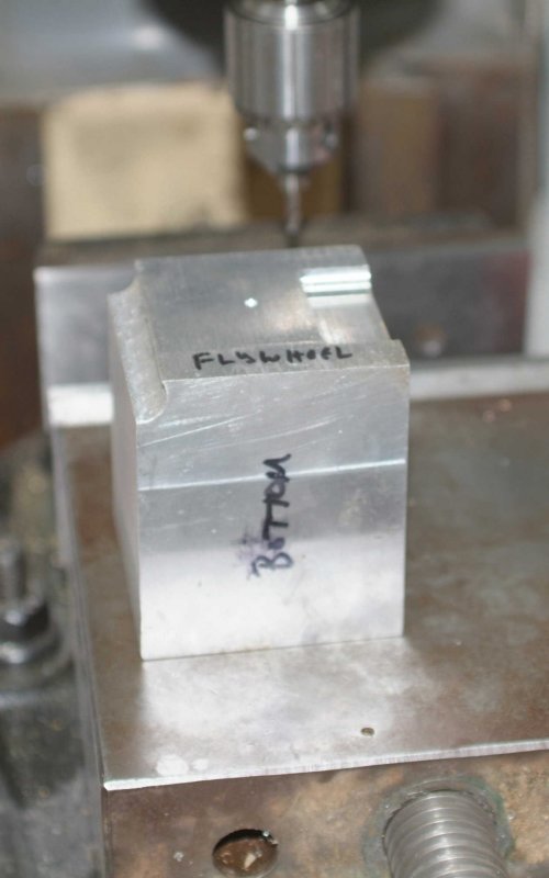
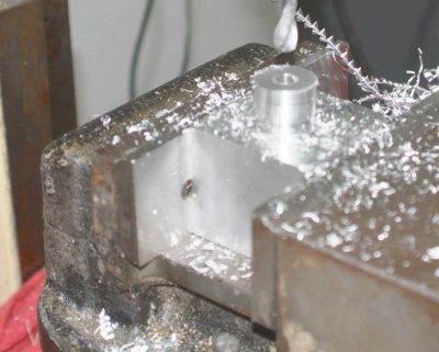
Since there is extra material in the Z direction I center drilled the crank location 1/2" higher than the plan would indicate. So the engine will have a thicker base, allowing it to sit level and clearing the flywheel. Once I had a hole to locate with, it was on to the lathe to mount the 4-jaw.

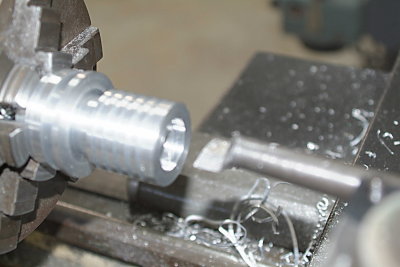
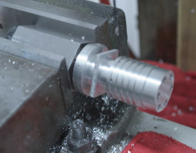
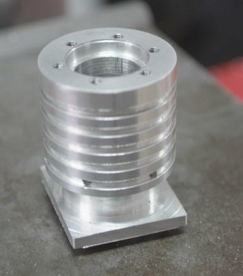
I am now a member of the Maryak fan club having removed large amount of swarf from a block of Al:

large.jpg


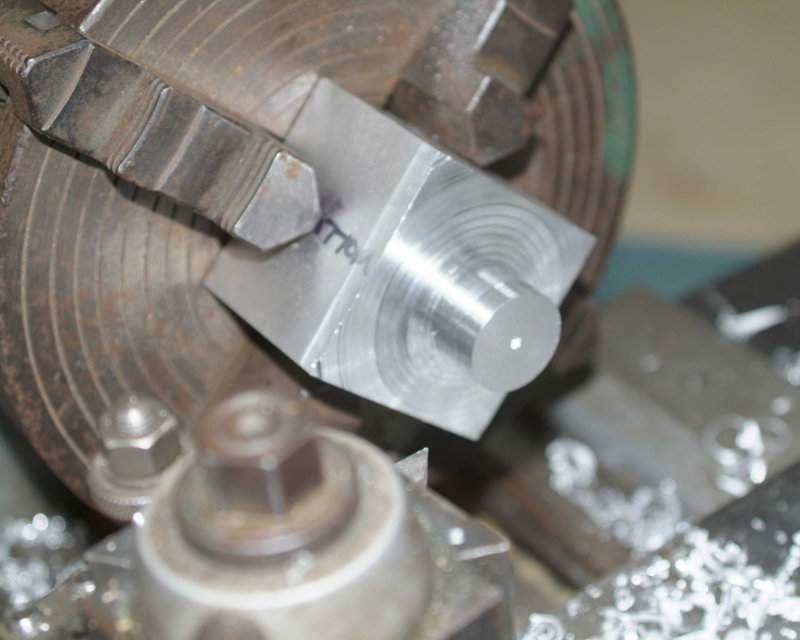
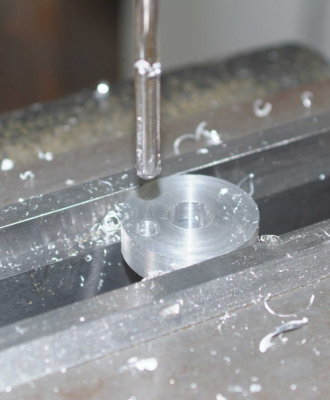
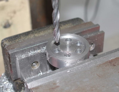
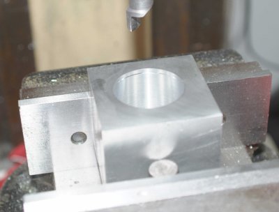
I don't trust the flatness of the chuck face, so the bearing was left slightly oversize. I'll drill the hole for the crankshaft on the mill since the opposite side is flycut flat.

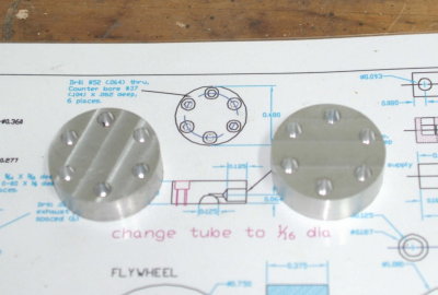
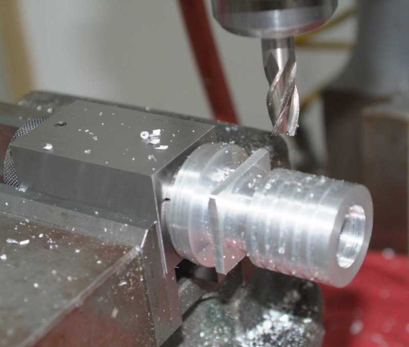
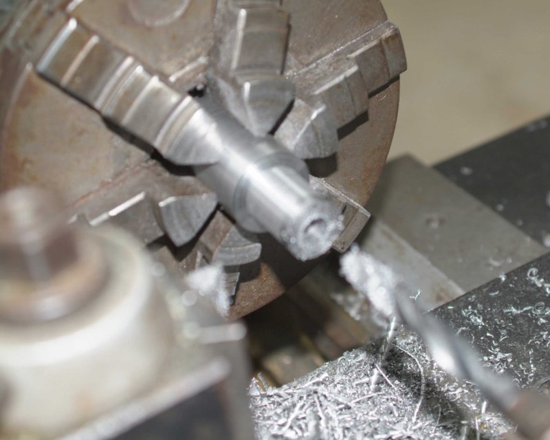
I had some steel rod that was a suitable size for the pistons, so I decided to attach these next. They will be .75" x .75". I cut one a couple of thousands too small and the other a couple too large, but since the cylinders will be bored and lapped they can be made to fit.

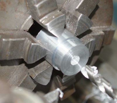
After turning the diameter, I drilled them .5" deep with a 3/8" bit. Then parted off slightly long:

large.jpg


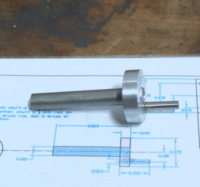
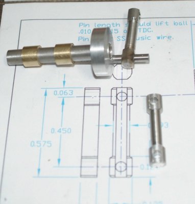
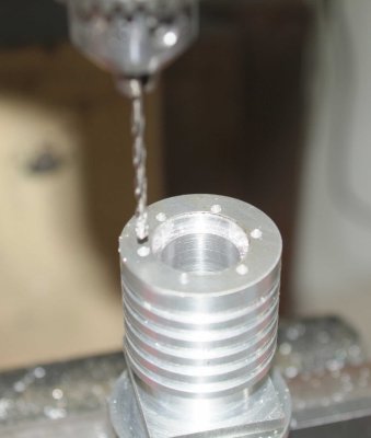
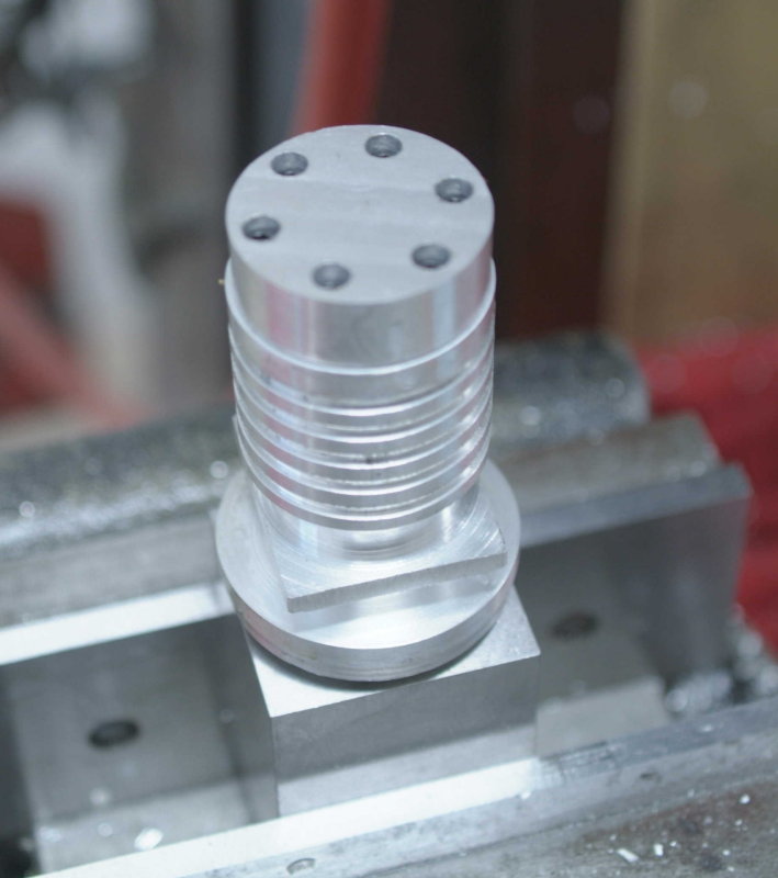
Finished them at the mill. First I milled to length, then using a 3/8" roughing mill I made the bottom square at .54" deep and then elongated the holes to give clearance for the connecting rod. Finally I drilled and reamed the holes for the wrist pins.

large.jpg


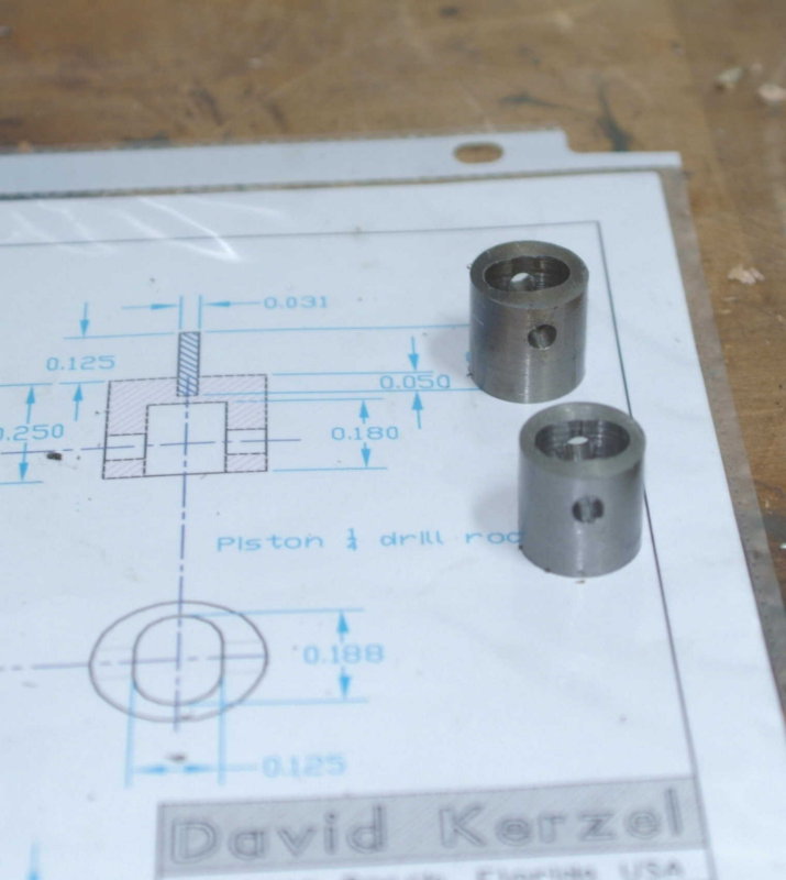
I didn't drill holes for the "valve" pin as I'm not sure what size steel ball I will find for the valve. It will probably be 1/8" drill rod.
 
Nice work. Thanks for the pix and documentation. This engine looks interesting. Do you have a photo of a completed one?

Cheers,
Phil
 
Thanks for the link. Here's to your success in this build

Cheers,
Phil
 
I had an hour or so of shop time befor lunch and made a bit more progress. First, I drilled the hole for the crankshaft. It's deep enough (1") so that then the crankcase is bored out it will be through. The shaft is 3/16" steel, but since it will ride on bushings I just used a 3/16 drillbit.

medium.jpg


Next I started on the crank. Turned some aluminum rod down to 1-1/8" diameter by 3". Then drilled hole for the crankshaft 11/64 and 4" deep. Then parted off.

medium.jpg


On to the mill to ream the crankshaft hole and drill/ream the hole for the crank pin.

medium.jpg


Finally cut the shaft and pin and pressed them into the holes. The shaft is a slip fit and will need some loctite. The pin was a tight fit and needed the arbor press to go in.

medium.jpg
 
Good work kvom. Thanks for the progress report,

Cheers,
Phil
 
looking good.............the way you are going it should be running by next weekend :bow:

chuck
 
Had another short session in the shop this afternoon. I made the two bushings out of some 1/2" brass rod. Drilled and reamed to 3/16, then lapped with some emery cloth and scotchbrite until they fit over the crankshaft.

Then I cut two discs for the cylinder heads out of some 2" aluminum rod. I turned a portion down to 1.5" and then parted them off. On the first one the tool bound up about halfway in, and I finished the cut with a hacksaw. For the other I made a double width cut with the parting tool until there was only a sliver left, then cut with the hacksaw. I will be glad when I get the bandsaw working. Then I faced both discs flat to length on the mill.

Tomorrow will be a learning experience, as I will use the boltcircle function of the mill DRO to locate the holes for the heads. Kerzel drilled with the heads held in a chuck on the rotary table, equipment I don't have.

I will use 5-40 screws for the head as I bought a box full from Enco.
 
For some reason the DRO's bolt circle routine doesn't match the manual (or else isn't present). In any case it was easy to caculate the coords of the 6 holes for the cylinder heads. Then it was crank the table around for center drilling, drilling, and countersinking 12 holes.

medium.jpg


Then I found a piece of 3/8" round steel rod in the bin that was just long enough to make the two connecting rods. Took longer than I expected to do the turning on the lathe. Later in the evening I finished them on the mill. The tricky part was finding just the right combination of parallels to allow them to chuck in the vidr for milling the flats and drilling the holes.

On the final hole the steel apparently work hardened as the drill wouldn't cut the last little bit. I had to turn it over and drill from the other size, making the hole slightly out of round. In any case it won't be visible in the end.

medium.jpg


In retrospect using 1/2" al rod would have been easier all around.
 
Looking good Kvom. We all keep a folder labeled "Retrospect". When we do the next project that is where we find many of the instructions ;D

Cheers,
Phil
 
I went to my Tuesday machining class tonight and never touched the mill or lathe. Instead I accumulated/borrowed stuff I need to make progress on the engine:

1) Set of 30-60-90 and 45-45-90 angle plates plus some .5" steel plate to make a set of my own. My plan is to mill these tomorrow and use the school surface grinder on the edges on Thursday.

2) Some pieces of 1.5x1.5" aluminum bar to turn the cylinders

3) A boring bar
 
I found a nice heavy piece of 12L14 round steel 2.5" in diameter in the school scrap bin, so that becomes the flywheel. Since multiplying dimensions by 3 increases volume by 8 times, this will be approximately 3 times the weight of the flywheel on the original, even if it's smaller than it would be with a straight scale up.

Since my prior engine's "bling" spoked wheel didn't merit nomination for POTM ;D, I decided to go with the classic 6-hole design. Beats 8 hours cranking on the old rotab cutting A2 steel.

medium.jpg


I borrowed the set of angle plates from school and used them to make my own copies from some "mystery" steel plate. Enco wants $22 for that set, so it was worth the 30 minutes or so it took to machine them. I will try to surface grind the edges at school, but even as they are they are reasonably accurate.

medium.jpg
 
I have been trying to make a cylinder, and screwed up the first two tries using 1.5" square aluminum bar. I since discovered that my mill head was out of tram, thanks to a defective cheapo DTI. I retrammed with a better quality DI and seem to be in better shape.

Not having another piece of 1.5x1.5, I decided to use a piece of 2" round stock. Got the profile machined and went to try the new boring bar setup after drilling through with a 41/64" drill. It was a tight fit, but did manage to bore it one of the pistons (a couple of thousand undersized still).

medium.jpg


I had purposely machined a 1" round on the end to enable me to chuck the piece in a 5C collet. So with it chucked in the square block I machined the mounting flange (which will now be a rectangle with 2 1.5" sides. Still plenty of room for the mounting screws in the corners.

large.jpg


Still in the collet block, drilled and tapped the holes for attaching the head:

medium.jpg


What do you know, it fits!

large.jpg


Now I transferred it to the hex collet block to drill the 6 exhaust holes

medium.jpg


Next time out I will part off and finish milling the bottom flange, plus drill the corner holes. I hope I can make another one that looks the same.
 
looking good Thm: 8)

the part i like about your post is "What do you know, it fits!" you make it sound like you had some doubt that it wouldn't fit :big:

keep up the great work

chuck
 
Ain't it a great feeling spending time on parts that are supposed to match, and they do? ;D

Great job!


Kevin
 
I managed to finish boring the crankcase. I started it on the lathe using the Cedge-design boring bar holder, but I found it too difficult to get everything lined up perfectly straight with the 4-jaw chuck. So I bored it to 1" and then mounted it on the mill to finish out to 1.5". With the quild feed at the minimum speed the finish of the bore is very good (although a precision surface isn't needed here).

medium.jpg


I also parted off cylinder#1 and turned the bottom surface. It still needs the mounting holes and to chamfer the inner bore at the bottom to clear the piston rod.

medium.jpg
 
Really looking good! Can't wait to see the finished engines (and a video?)!

Chuck
 

Latest posts

Back
Top