Jim builds his second v-8

Home Model Engine Machinist Forum

Help Support Home Model Engine Machinist Forum:

This site may earn a commission from merchant affiliate links, including eBay, Amazon, and others.
Thanks guys for code info. I think macro would be the way to go. if I was making gears or splines with lots of teeth I'd have to get some type of loop working. Its too time consuming to repeat 100 lines of code when a macro or loop of some type would do.

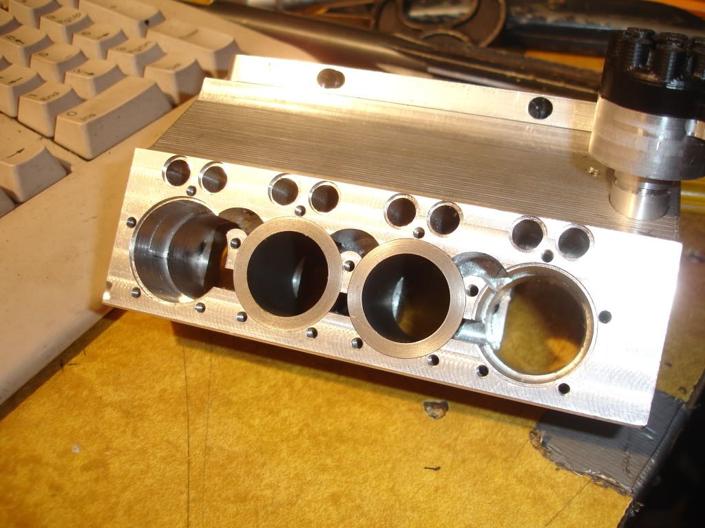
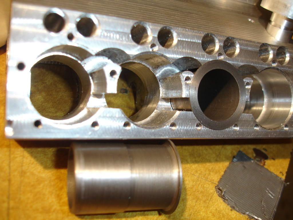
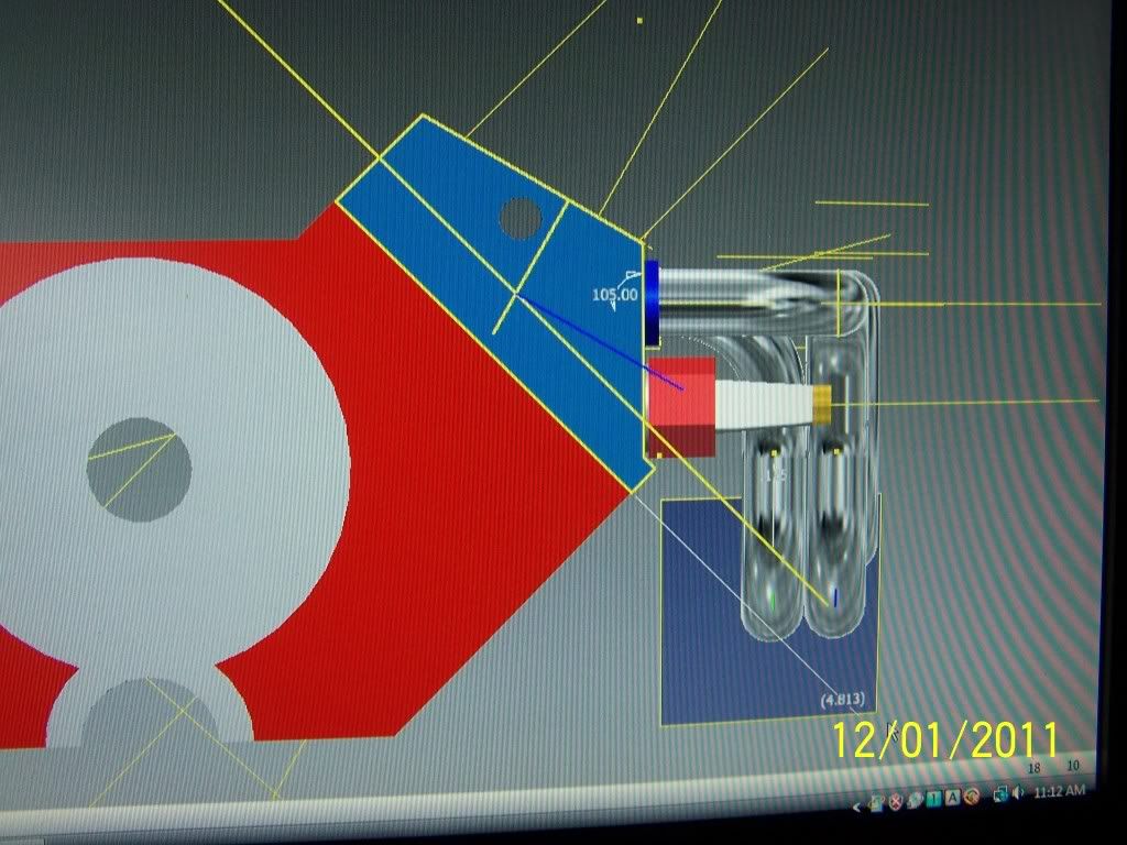
About the engine design, style, type: Its gonna be an overhead valve v8. the picture shows the cylinder holes in which I'll insert sleeves, picture coming.
 
Hi jpeter,

First off all compliments for your build, its looks fantasticband the finishing on your parts is very nice. :bow:

In addition to the M98 there is a trick to move for example the rotary table inside the sub rotine. When you enter the subrotine you switch to the relative distance mode G91. Then move the rotary table for the desired amount and in the next line switch back to absolute disctance mode with G90 to the rest of the rotine code.

I will check how to repeat a rotine for x times, cannot find it now.

Regards Jeroen

 
Hi jpeter,

To repeat a command you can put the letter L behind the gcode. In the example of Steve it would look like

M98 P100 L8

Where 8 is the number of repetition.

Good luck, regards Jeroen
 
Got in some shoptime yesterday. Worked on installing some sleeves. Haven't yet decided how I'm gonna return water to the radiator. Still thinking about that. It'd been nice if I'd planned water passages when I was designing the heads. Seems to have been an oversite. I hate it when that happens.

DSC02289.jpg


DSC02290.jpg
 
Looking good jim, what are you using to seal the bottom of the liners from the oil in the sump? loctite or similar?
 

Really nice work Jim!
 
Chaffe said:
Looking good jim, what are you using to seal the bottom of the liners from the oil in the sump? loctite or similar?
I'm thinking loctite but open for suggestions. Hey, thanks for the comments guys.
 
Jim, I used locktite with an interference fit between the liner and block. I tested it with a vacuum pump, it held a vacuum for a few hours before I took it off. I have yet to test it since I ran the engine, and it has yet to see water, so I cannot be certain it will work, but I am confident.

Great work BTW, this is turning out to be quite the little engine. The way your water jackets are open to the bottom of the head is great, this should aid in the cooling of the head a little bit I would think.

Kel
 
kcmillin said:
Jim, I used locktite with an interference fit between the liner and block. I tested it with a vacuum pump, it held a vacuum for a few hours before I took it off. I have yet to test it since I ran the engine, and it has yet to see water, so I cannot be certain it will work, but I am confident.

Kel

Yeah, I happend across Conley some time back, maker of the Conley V8s. I ask him then how he sealed his engines and he said, "Loctite." I've got the fit such that I need to push the sleeves in with thumb pressure so Loctite outta work. I might loosen the fit a little yet. I don't want to chance distorting the sleeves after working so hard to lap them round.
Thanks for the comment.
 
jpeter said:
I ask him then how he sealed his engines and he said, "Loctite."

Hi Jim!

Try the green loc-tite. It is thinner than the red and will creep into tighter spots. I painted both mating surfaces with a Q-tip after cleaning with brake cleaner. Should do ya!

If you can wait another month the Loc-tite rep should be at the meeting next month.
 
Hey Steve, thanks for the tip. Wait a month, I don't think so.

My plan for tomorrow is to get on the cad tube and try to design an intake manifold that incorporates a water return passage from the back cylinders to center front. I think I can take water up throuh the head into the intake manifold. Gonna be tough but I'm gonna try it. What do you think of that idea?
 
jpeter said:
Hey Steve, thanks for the tip. Wait a month, I don't think so.

My plan for tomorrow is to get on the cad tube and try to design an intake manifold that incorporates a water return passage from the back cylinders to center front. I think I can take water up throuh the head into the intake manifold. Gonna be tough but I'm gonna try it. What do you think of that idea?

What about some tubing in the lifter area under the intake manifold? Come out the block and use a tee fitting to head back to the front.
 
stevehuckss396 said:
What about some tubing in the lifter area under the intake manifold? Come out the block and use a tee fitting to head back to the front.
Thats a good idea too.
 
hi,

does anyone know from where i could buy materials like the cold rolled steel used for the cranckshaft etc. im looking for a site which could ship to Malta.

Thanks
Drei
 
jpeter said:
Yeah, I happend across Conley some time back, maker of the Conley V8s. I ask him then how he sealed his engines and he said, "Loctite." I've got the fit such that I need to push the sleeves in with thumb pressure so Loctite outta work. I might loosen the fit a little yet. I don't want to chance distorting the sleeves after working so hard to lap them round.
Thanks for the comment.

Got to agree on the loctite. The "sleeve" formulation is great stuff, but does count on having clearance between the head and the liner, or whatever two surfaces need to be secured. It's pretty disturbing to generate intentional clearances of 0.001" or more, but less clearance and there's no seal or bond.

Really nice work! Thanks for posting. :D
 
Drei said:
hi,

does anyone know from where i could buy materials like the cold rolled steel used for the cranckshaft etc. im looking for a site which could ship to Malta.

Thanks
Drei
ebay is a good place, ebay uk may ship to malta
 
Well, I think I laid off long enough. A couple of weeks ago I decided to get back to the v8. I've been walking in circles for some time trying to deal with the thin heads and how to route the cooling system water back to the radiator. Seems the only good way was to make new heads. So that's what I'm gonna do. Of course to avoid the spark plugs and all the other features of the heads by the exhaust manifold I decided to make the exhaust header first. I first drafted up the head and manifold. Then I mocked up exhaust outlets on an aluminum block, screwed on the flanges for the manifold, bent up some 1/4 od stainless tube into a header, milled some flanges, then bolted the flanges onto the block. Here's how they look on the screen. As of yet the head is only in the computer.

000_0074.jpg

000_0073.jpg

000_0072.jpg


+1 for loctite cylindrical bonder. The old 620 or the more modern 680.

It's not coming out with out a torch......that's no exageration.

I have several 6 HP ultra precision spindles running in various far east countries 24/7 with the motor rotors put on with 680 and nothing else....my calculations state that the rotor would need a 80 TON press to be removed based on a 4000 psi shear strength....It would take about 450F to break the bond.

Dave
 
Back
Top