Jim builds his second v-8

Home Model Engine Machinist Forum

Help Support Home Model Engine Machinist Forum:

This site may earn a commission from merchant affiliate links, including eBay, Amazon, and others.
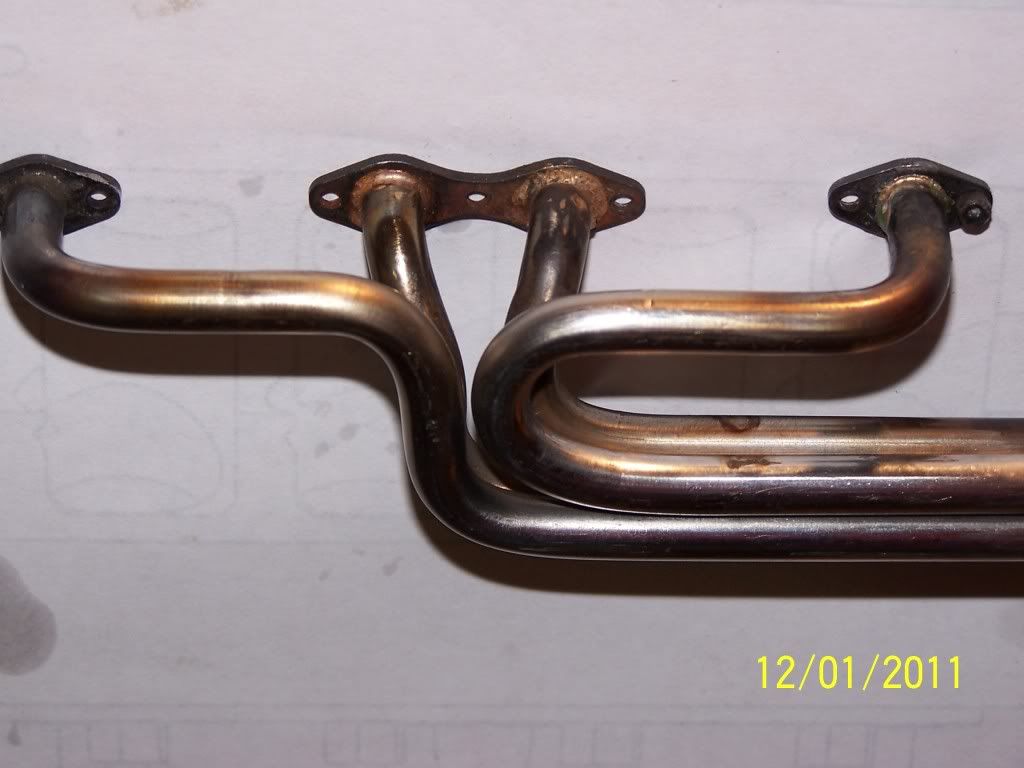
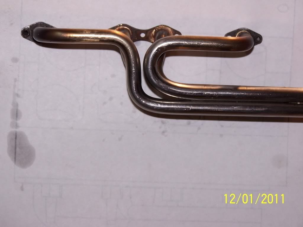
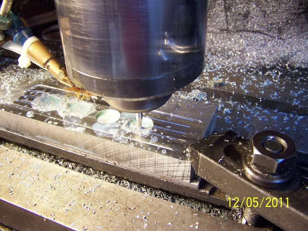
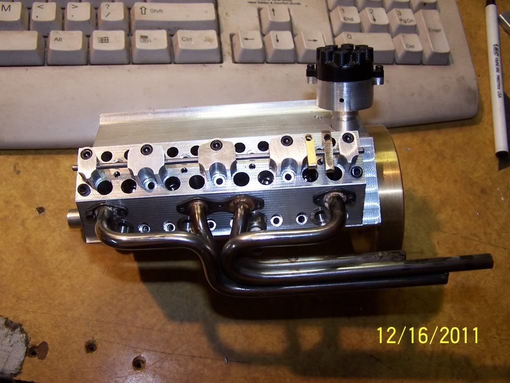
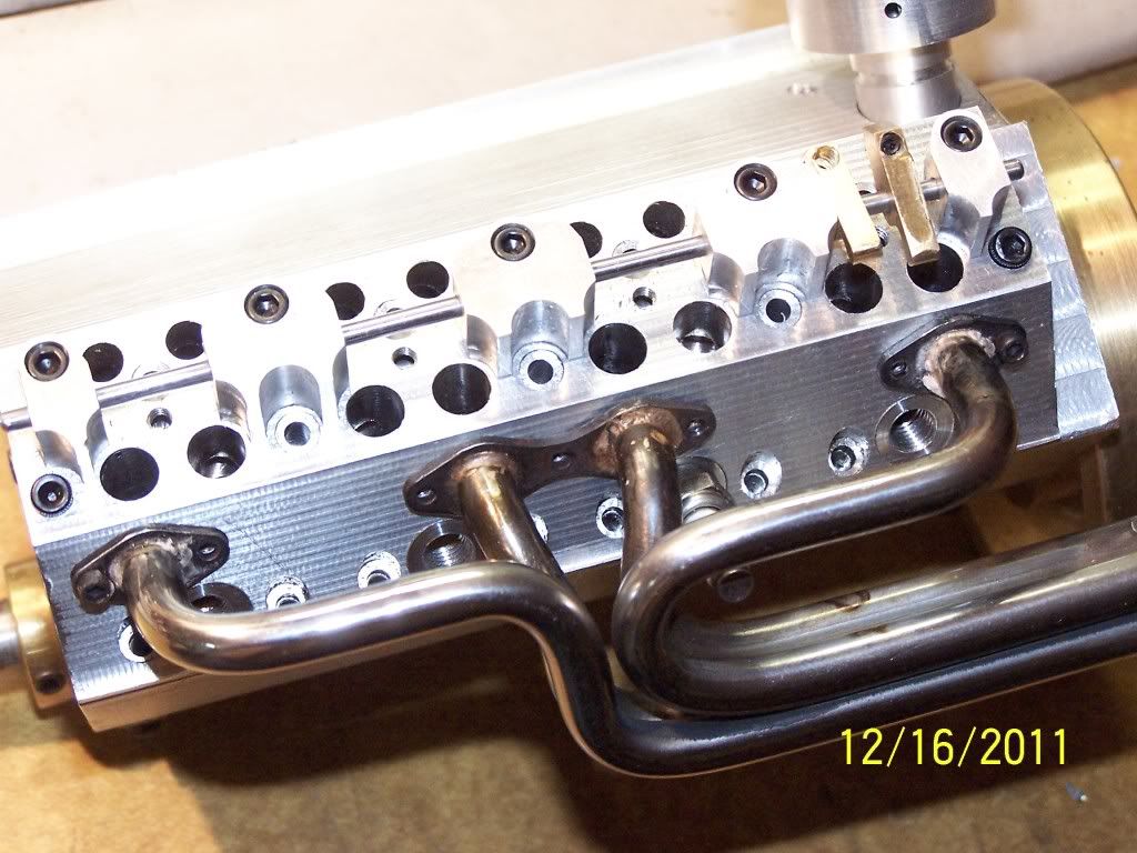
I bent up some 1/4 od stainless tube and silver soldered it to the flanges which, by-the-way, were screwed to a block with 2-56 cap screws. before bending I filled the tube with soft solder. I'm sure better materials exist but I had the soft solder. The bending die has a 0.450 diameter so the bends have a 0.225 radius. I think with spring back and all they're more like 0.25 radius. For a bending die I grooved a 1 inch dia. rod the proper depth by placing the rod in my spindex and hand feeding a 1/4 inch ball end mill until I had the desired depth. I think I took 2 passes. I widened the slot 0.002 and made another pass. The shoe is flat with a 1/8 radius to match the tube. The bends are easy. Getting the bend in the right spot is the hard part. Here's one side. Needs polish. Now I need a mirror image for the other side.
exhaustmanifold2.jpg

exhaustmanifold1.jpg
 
Thanks for the info on the locktite. No doubt that's what I'll be using. A company rep was going to give a lecture at the club meeting on Locktite, with lots of free samples but he's yet to show up. I'm still waiting.
 
Had to make a couple of heads. First I machined the combustion chambers.
100_0527.jpg


Finished that and drilled some holes too.

100_0528.jpg
 
I flipped the head over next and milled the top surfaces.
100_0530.jpg


Got that done.

100_0532.jpg
 
Missed photographing cutting it out. Drill and tapped some holes for spark plugs, exhaust manifold and rocker supports. Milled and bolted on some rocker supports, exhaust pipes and added a spark plug for the photo. Got 4 extra holes too. Gonna have to plug them cuz they go directly into a 5/32 water passage drilled from front to back. The idea is to have cooling water enter the front of the block, circulate around the sleeves, exit the block into the head where it travels through the head to exit into the intake manifold at the front of the engine.

100_0536.jpg

100_0537.jpg
 
Oh boy! Another thread I have missed.

Jim, love those headers, nice work!

Now I'm off to read this thread from start to end ;D
 
The build's been going slow but I have made some slight progress. Below is a picture of the water pump housing with the impellor. I've got no pictures of the base. The water pump base incorporates the timing gear cover and the lip seal I intend to use on the front of the crank shaft.

100_0549.jpg


Here's the pump attached to the base. The base is attached to the front of the engine. The big hole in the base through which the crank extends is to provide for a 3/4 od lip oil seal.

100_0551.jpg


Notice too, I've got the oil pan in place. Below is a better picture of the oil pan.

100_0547.jpg


So far so good.
 
Looking really nice. I can't wait to hear it run.
Also, I noticed your drawing textbook in the background. I use the same one!
 
Jeremy_BP said:
Looking really nice. I can't wait to hear it run.
Also, I noticed your drawing textbook in the background. I use the same one!

Yeah, that book's been around for a while. :)
 
Spent time today in the shop. Finished the front and rear motor mounts. Raised the front up 1/8 inch higher than the back. Going to level the carbs, 2 carbs I think. Outta look nice that way, don't you think.
100_0562.jpg


Regarding the book comment, this photo includes another one of my favorites, Technical Drawing by Giesecke, Mitchell and Sepncer. Its been around a while but I still refer to it. Maybe I'm showing my age, eh.
 
I've been working on the intake manifold. Here's a short video of the mill running. (These are videos. You need to click on them to play)


Well the mill ran until this piece came out.

Next I made a cover for the tunnel. I don't yet know where I'm putting the carbs so I spotted them but didn't drill for them. The engines setting in its stand is 1/8 inch higher in the front so I beveled the top of the tunnel cover cover to level the carburetors.
I screwed on the tunnel cover. I hope you like my music. I'm gonna have to learn to hold my ipad horiontal too when videoing.
 
I needed 16 valve guides. I've standardized on 1/8 inch valve stems but GB in recent posts suggested 3/32 inch stems for engines of the size I'm making is a better choice so that's what I've settled on here. My standard procedure was to turn the outside of the guide and then carefully spot drill the center and carefully drill and ream for the stem. I have a seat cutter. The process involved pressing in the guide then using the guided seat cutter to cut the seat in the head. Well, seating the valves has always been a tedious process. I was worried about how effective a seat cutter guiding on a pin so small, 3/32, would work. My plan was to try to make valves guides that had the stem hole and perimeter dead nuts concentric, then guide the seat cutter on the reamed hole in the head. Is that going to work? We'll see.

I checked some previously made guides for runout only to find most had at least 0.010. I needed a lot better. Here's a short video showing me checking a valve guide for runout. This ones about 0.003 out. It's not bad but not good enough.

 
I changed the process. First I cut the stock to length, next I spot drilled and drilled the hole, then reamed the hole to final size. I then turned a steel tapered mandrel on to which I mounted the blanked out guide.

a4a34bc9.jpg


I mounted the blank on the mandrel and turned it to about 0.005 oversized.

d1c98141.jpg
 
I found when they came off the steel mandrel they were still not concentric thus the reason for turning them oversized. Next, I mounted them on a brass mandrel and turned them to final sized.

050f9582.jpg


They came out quite concentric. Here's a video of a testing of a typical guide.


I think they'll work.

As an aside, here's a picture of my collet storage device. Obviously it's a 5 gallon plastic bucket that's been drilled full of holes with a hole saw.

f471c584.jpg


The days in the shop I've learned something are good days.
 
Jim, your engine is coming along great. It's hard to believe that your were getting that much runout with your first machining operation on the guides. With a center drilled hole almost to the diameter of your following drill it should have been pretty darn close. I'm glad at least mounting them on a mandrel solved the problem.
George
 

Latest posts

Back
Top