Indicator Holders and Such...

Home Model Engine Machinist Forum

Help Support Home Model Engine Machinist Forum:

This site may earn a commission from merchant affiliate links, including eBay, Amazon, and others.
zeeprogrammer said:
Robert: Close. Get rid of the hole on the left and move that center screw to the left. Get rid of the screw on the right. Now put two side by side with that screw going through both. Tightening a nut on the end of the screw will squeeze both splits and clamp the rods that would go through the other two holes. Articulates. Doda on one end can hold the DTI.

I'll be doing some drawing (sketching, scribbling) this weekend. But you got it.

Changed the pic some, suppose if the end hole was positioned right it would also grab the dovetail on your DTI. A socket head cap screw turned down to be a tight fit into a recess, dab of loctite, knurled k'nob. Of course I still went with the multi purpose route :)
 
After playing with my aluminum (hey!) I can see why steel would be better. the smaller diameter lever bends and I suspect the threading to attach it to the nut won't last long.

Smiles evilly to self while resisting the urge to say, "Told you".

The blocks are probably going to be 0.5x0.5x1.0". A 3/8" hole for a rod. A something bigger than 1/4" for the screw. The nut then would take a 1/4-20 and be no more than 0.5" in diameter.

What prevents the 1/4-20 from turning when you attempt to tighten the nut?

First, since you're contemplating hand tightening the lock nut, I would use a finer thread for more mechanical advantage - say 10-32. This would also allow you to make the block a bit smaller - an advantage when getting into tight areas. You don't need something as big as a 1/4-20 to clamp a couple of 3/8" rods.

I would would replace the bolt with a stud and secure it with Loctite 609 (not their threadlocker products). Drill through the block at tap drill size for the selected thread (#21 for a 10-32), thread a bit more than half way through the block, then open out the rest of the hole to clearance size (#9 for a 10-32). After slitting the block, Loctite a threaded stud into the thread so it projects out the clearance hole by 5/16" or so. Add 10-32 knurled knob.

If you don't want to screw around making a dovetail in your blocks, think about designing some holes into your block to accept the two dovetail clamps that came with your DTI. A setscrew could be used to secure the clamps to a block. Several holes would give you a wide variety of mounting options.


mklotz said:
Smiles evilly to self while resisting the urge to say, "Told you".

Yet somehow manages to say it anyway. :big:

'Smiles evilly to self'...hm, you said something about 'insanity' in another thread?

mklotz said:
What prevents the 1/4-20 from turning when you attempt to tighten the nut?

I would use a finer thread for more mechanical advantage - say 10-32.

I would would replace the bolt with a stud and secure it with Loctite 609

think about designing some holes into your block to accept the two dovetail clamps that came with your DTI.

'from turning'...I'm thinking the taper...just like when a chuck is put into tailstock. I asked the question in case I didn't taper. Jim mentioned silver soldering the end. I'll get back to that in a sec.

'mechanical advantage'...ah another learning...finer thread, more advantage. Thanks. Actually...had mentioned 1/4-20 but the plan was to go out this afternoon and get a little variety of bolts nuts etc...so I can 'play wif them' and learn.

'secure with loctite'...just a sec

'dovetail clamps'...I will. although I was trying to figure out a way to mill without having a dovetail cutter.

Foozer: Yes that's it. I like the idea of drilling a hole to make the dovetail clamps. I may try that.

Now for the loctiting, silver solder....that would mean the screw is forever there and of a fixed length. If the screw is removable...then one could gang these together? Imagine 3 of them...maybe put washers in between to keep the force on the middle one? Why I would do that I don't know. Maybe only one on a rod to act as some kind of stop?

I've yet to see this on this forum...is it heresy to consider a star or lock washer?
 
zeeprogrammer said:
'mechanical advantage'...ah another learning...finer thread, more advantage. Thanks. Actually...had mentioned 1/4-20 but the plan was to go out this afternoon and get a little variety of bolts nuts etc...so I can 'play wif them' and learn.

'secure with loctite'...just a sec

'dovetail clamps'...I will. although I was trying to figure out a way to mill without having a dovetail cutter.

Foozer: Yes that's it. I like the idea of drilling a hole to make the dovetail clamps. I may try that.

Now for the loctiting, silver solder....that would mean the screw is forever there and of a fixed length. If the screw is removable...then one could gang these together? Imagine 3 of them...maybe put washers in between to keep the force on the middle one? Why I would do that I don't know. Maybe only one on a rod to act as some kind of stop?

I've yet to see this on this forum...is it heresy to consider a star or lock washer?

If you don't want it semi permanent use a heli coil insert for the threaded end of the stud. Saves the wear and tear on the AL threads.

Star washers, great for electrical grounding applications, mar the surface as most lock washers do. Not required for the finger pressure load in this case.

In Al you could use a wood router bit for the dovetail, trip to local hardware catalog should turn up a suitable one.

AL seems to prefer a finer thread for studs and bolts, but the threads deform, gall up easily with repeated use.

Changed sketch again, incorporated Marvs stud idea. Also you can use a ball turner and get fancy making attachments :)

Ok make a sketch of what your doing, I'm having way to much fun
 
Now for the loctiting, silver solder....that would mean the screw is forever there and of a fixed length. If the screw is removable...then one could gang these together? Imagine 3 of them...maybe put washers in between to keep the force on the middle one? Why I would do that I don't know. Maybe only one on a rod to act as some kind of stop?

I've long contended that it's impossible to design the perfect tool on paper. You can only learn the design features that you overlooked by working with an actual tool that fails to do all the things you left out of the design. Features you thought were important will turn out to be frills, obvious stuff will be overlooked, etc.. That's why we build prototypes - to avoid what I call design paralysis - spending more time designing than it would take to build a prototype and exercise it.

So my approach has always been...

Design something *simple* that will do the immediate job to hand.

Use it and keep track of the things you should have done differently, the features you failed to include, etc..

Design the new iteration of the tool including everything you learned above.

Rinse, repeat, etcan (et cetera ad nauseum).


Loctite breaks down with heat. Put a torch on it and you can always get it apart. That's why Loctite isn't used on parts of engines that can get hot.

The dovetails on a DTI are pretty small (<1/4"). I doubt you'll find a cutter in a woodworking store. I got a tiny one from Brownells - used for dovetailed sights on firearms. But, why bother? You've got the clamps that came with the indicator. Use those. Mount them so they're removable.
 
mklotz said:
The dovetails on a DTI are pretty small (<1/4"). I doubt you'll find a cutter in a woodworking store. I got a tiny one from Brownells - used for dovetailed sights on firearms. But, why bother? You've got the clamps that came with the indicator. Use those. Mount them so they're removable.

Cut the dovetail halves on two pieces and then screw them together.

Alan


The dovetails on a DTI are pretty small (<1/4"). I doubt you'll find a cutter in a woodworking store. I got a tiny one from Brownells - used for dovetailed sights on firearms. But, why bother? You've got the clamps that came with the indicator. Use those. Mount them so they're removable.
[/quote]


When I made a copy of the "Zero it Indicator Holder" the plans said to use a small jewelers type triangular file. It worked really well. The dove tail on my indicator fit nicely.

Ron
 
mklotz said:
I've long contended that it's impossible to design the perfect tool on paper. You can only learn the design features that you overlooked by working with an actual tool that fails to do all the things you left out of the design.

I agree Marv. Just collecting info and tips. And there's been some good ones whether I incorporate them in this design or not. Even in the best design...some one will come up with an improvement.

In the meantime, I have no problem taking advantage of others' work. And Foozer is doing a pretty good job designing this. :big:

Thanks Alan and Ron. This is one of the great things about this forum...lots of ideas.

On my way to HF I thought some more about the nuts and worried a little about the strength. I have some 1018 steel left from the last project that's close to the right diameter. I think that will make for better nuts (knobs). I see that Foozer was thinking along the same lines.

No much luck in getting bolts of any kind today. I'll have to order some. So now to do some drawing...
 
Attached is a (poor) drawing of the half joint. It's similar (nearly identical) to the one in MEW.

Question: If the hole is 3/8 then there's 1/16 of material left. Is that enough? If so...then it can be used to hold the 3/8 pin on the DTI.

As I mentioned...I don't know about the screws/nuts. I'm going to order some different ones and try them. A flat head socket might be easy but the diameter of the head, as well as the depth, comes into play. (Obviously, the diameter should be something less than 1/2.) I have to go find some dimensioning information.

Related to the diameter needed is the nut. I'm going to make it out of steel. I'm thinking 3/4" diameter, knurled. Maybe 1/4 or 5/16 thick. [EDIT: Point is...it has to be wider in diameter than the countersink or taper.]

You'll also see in the diagram the setup for tramming the mill. 6 half joints and 3 rods. I could reduce to 5 half joints if the fifth one is unique in that it has some means to mount the DTI.

Okay...that's what I'll try. It'll be a few days...have to get some bolts.

Oh...maybe longer...I just realized I have to make a vise stop (since I'm making 6 or more identical half joints). Two tools! That should take some weight off!

Now let's see if the attachment worked...

[EDIT: It did. Also reminded me...you can see I put two tapers in the half joint. It may end up being two countersinks. But the point is that it's the same both sides...I don't have to think about what side is what. Well...unless I'm stupid enough to try and put the screw in the rod hole or vice versa....and yes I am.]

View attachment half joint.pdf

View attachment half joint.pdf
 
Sure is quiet tonight. Must be because of the 4th. Wife is in Belgium, daughter #1 is trying to keep the contractions at bay, daughter #2 is...is...oh yeah...at the beach with meathead #2.

So...the vise stop. I looked at the pic that Shred was kind enough to post on "Open Column Launch Engine from Kit"...reply #27 out of 430 back in May 19. Seems like ages..

Attached is a (even poorer) drawing of what I'm thinking.

The jaws of my vise stick up a little over 1/8". So this should fit.
I wanted the part that goes into the vise to be less than 1/2" wide (the half joints are 1/2").

The depth into the vise is 6/8 but I'm thinking of changing it to 5/8..that way the 1" stock I have will do just fine.

1 1/2" long for 3 bolts. Any reason why it couldn't be 1" and just 2 bolts?

On that note...Marv mentioned 10-32. From the little I've seen, 10-24 seems more popular. Any thoughts on that?

Can I start cutting now?


View attachment vise stop.pdf

View attachment vise stop.pdf
 
zeeprogrammer said:
Attached is a (poor) drawing of the half joint. It's similar (nearly identical) to the one in MEW.

Question: If the hole is 3/8 then there's 1/16 of material left. Is that enough? If so...then it can be used to hold the 3/8 pin on the DTI.

For this application, plenty of meat left. Only squeezing it down a few thousands, 3/8 rod and a loose 3/8 hole (+0.005 or so) Finger tight will hold just fine. Bore holes nice and smooth, reduce the scratch to crack, remove points of stress build up.

You know the contraption is gonna get heavy. Six blocks and hardware, adds up quick. Round over the ends and it'll drop some weight without effecting purpose. Quick sketch, guessed at the taper

block.jpg


block.jpg
 
Foozer said:
reduce the scratch to crack

???

My stock of reference books is rather meager. I tried google...but I'm sorry I did. :big:

Thanks. I'm starting to have withdrawal from cutting.
 
I must wake up 4 or 5 times a night and, nowadays, I'm always thinking about machining.

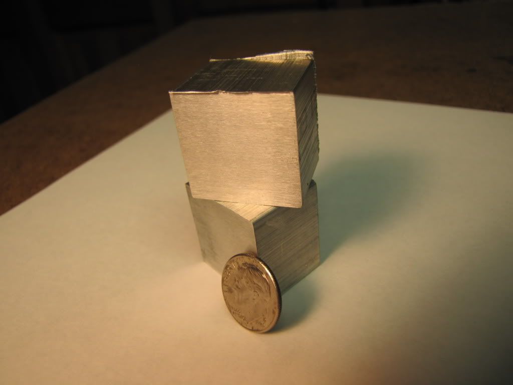
I started making the vise stop. Two pieces. Not too much to see here.

Here's the raw stock....

RawMaterial.jpg


Mounted in the middle so the vise pressure is the same along the jaw. The orange bit is my halloween foam to keep the parallels from moving about. So far, no matter what I do (i.e. using a mallet), the part lifts off one of the parallels as I tighten.

IMG_0262.jpg


Used my biggest end mill to get the biggest cut...

IMG_0263.jpg


I think I know enough to get one side flat and then use it as a reference for all other work. For example, when I flip if over and mill the other side, the two sides should be parallel. And, so long as I mill the sides, from the side, they should be square.

Still don't know when it's best to use 4-flute over 2-flute other than 2-flute seems preferred when plunge cutting.

I think the part's too small to flycut. Besides...this is about making the tools to tram the mill so it can flycut (i.e. the flycut would not be accurate).

A couple of things on my mind...

a) Two parts like this means a lot of milling cuts to make all sides square (although I may not do all of them).
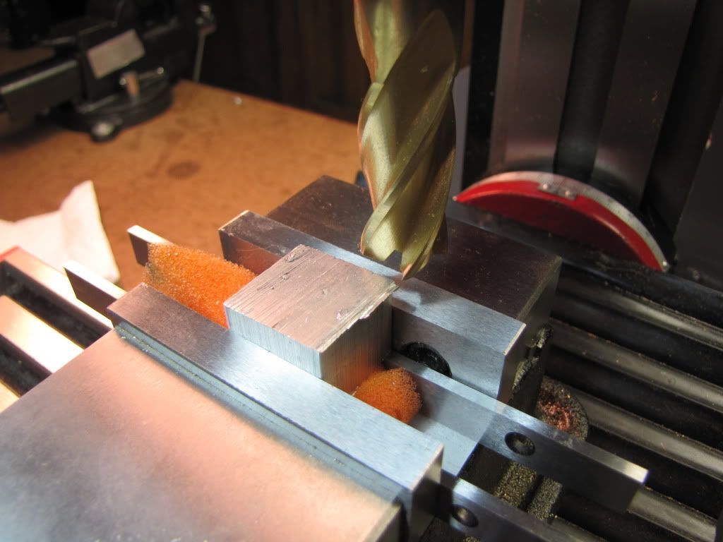
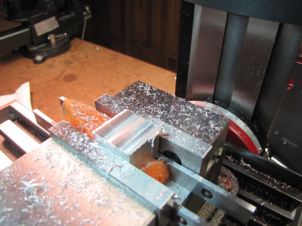
b) Once shaped I have to drill/tap two holes. Have to be a bit careful so the two on one piece line up with the two on the other.
c) Should this have started out as a one piece? Mill everything, drill the two holes, and then separate the pieces? After separation, tap two of the holes? How to separate? Maybe bandsaw then mill to clean up? The two faces are not critical. Maybe slitsaw? I would want to clamp what would be both pieces and that looks difficult. Use a small diameter end mill? Could clamp properly then.

But 'c' requires a bigger lump of metal...which, as it turns out, I have. But I don't have a way yet to cut it out of the piece I have.

All this for a vise stop. Interesting, not.
 
Don't flip your part over after facing one side. You'll still be clamping on saw-cut surfaces. Flip the now-smooth face agaist the rear jaw of your nice, square vise, and cut a second side square to the first. If the stock were big enough to hang out of the sides of the vise, I'll often cut a side or two during this setup.
Now, keep your first side against the back jaw, but flip the part onto the side you just cut. Stick something between the moveable jaw and the part if it still wants to lift. (cardboard, cardstock, a dowel, I've even used leather. ::) )
Skim a third side, and you're home-free. Now set the first side you cut down onto the parallels, and skim the fourth.

Yes, squaring up stock for both pieces is easier if they're still attached to each other.

Also, you're not the only one who wakes up at night thinking about machining.

Daughter #1, contractions, what? Cool, pre-congrats, man!
 
Vernon said:
You'll still be clamping on saw-cut surfaces.
Daughter #1, contractions, what? Cool, pre-congrats, man!

Does it matter that the sides were not sawn? They were the extruded sides...if you know what I mean. I'd also deburred before flipping. I suspect that still doesn't mean square so your approach is better.

Re: Daughter. Thanks. Early though. Not due till last week of August. But all looks good.
 
mklotz said:
Remember this?

NEVER REMOVE A PART FROM ITS PARENT STOCK UNTIL YOU ABSOLUTELY HAVE TO DO SO.

Yes. Although wetware is a bit solidified some stuff gets in there...and even better...manages to stay. :)

The choice was 'wait for a bandsaw' or 'get started with what I have'. It's more work in this case...but also more practice.

Actually, now that I'm rereading this...my question was "Should this have started out as one piece?". The answer, as defined by the rule you stated, is of course 'yes'. So I needn't have asked the question...I should just have pointed out that, in this case, I decided for reason above, to make it from two pieces.

Thanks Marv.
 
zeeprogrammer said:
???

My stock of reference books is rather meager. I tried google...but I'm sorry I did. :big:

Thanks. I'm starting to have withdrawal from cutting.

You know those times when you cut a coat hanger in two by bending it back and forth till it breaks, come on now, everyone has done it, takes a few back and forth's doesn't it. Try it and count the number of times it takes. Now take same coat hanger and put a little scratch mark, bend er back and forth (count) till it breaks again. The scratch (defect) concentrates the stress of the bending to itself. rather than across the full width of area under stress.

Removing toolmarks, scratches and other surface defects is more than cosmetic. There removal and the subsequent smooth surface finish (RH) reduces the effect of metal fatigue at any one point. You tie a half knot in a piece of thread to break the thread by hand, the knot is the defect which concentrates the force of the thread being pulled in opposite direction. Without the knot and good thread the "pull" usually ends up with the big eyed looked at where the thread was wrapped around your finger.

Googled "scratch to crack"? :) can only imange what world you suddenly found yourself exploring.


Does it matter that the sides were not sawn? They were the extruded sides...if you know what I mean. I'd also deburred before flipping. I suspect that still doesn't mean square so your approach is better.

Re: Daughter. Thanks. Early though. Not due till last week of August. But all looks good.

Personal opinion and like other various body parts, everyone has one, its the process of squaring up the stock that becomes the standard. What you start with is matters not, what you end up with does. If the tried and true procedure calls for XYZ sequence then that's the method to do and learn. Once that way is part of body and soul, deviations (shortcuts) are at the discretion of the user (at the cost of accuracy).

Posted by: Vernon
Also, you're not the only one who wakes up at night thinking about machining.

Few shots of Tequila will cure that
 
Foozer said:
"scratch to crack"?

Thanks Robert. I'll add that one to the tome of 'Hard to Find Definitions'.

Foozer said:
the process of squaring up the stock that becomes the standard

Yes. Should be standard first...then (maybe) discretionary.

Foozer said:
Few shots of Tequila will cure that

Was someone looking for a cure? ;D

By the way, I wanted to mention good job on the sketch of the half joint (although I won't go so far right now to round the ends - needs another tool). Are the dimensions of the taper sufficient or should there also be a note indicating the degree?

Is that the google sketch-up you were talking about? How long did it take to draw/modify?

Thanks.
 
zeeprogrammer said:
Was someone looking for a cure? ;D

Used to wake up in the night and look at the bride thinking "Now there is a picture to take home to MaMa" Maybe too much Tequila

By the way, I wanted to mention good job on the sketch of the half joint (although I won't go so far right now to round the ends - needs another tool). Are the dimensions of the taper sufficient or should there also be a note indicating the degree?

Is that the google sketch-up you were talking about? How long did it take to draw/modify?

Thanks.

Sketchup. There is a rounding over jig post somewhere on this board, real simple to fab. Taper was a guess, easily adjustable to suit bolt usage. Only took a few minutes to draw it out. I like sketchup for it makes sketches that i can read. Me, pencil and paper end up with a "What the Heck was that" results

EDIT:
HERE for a pic of a rounding over jig. Simple thing, piece of stock with locating pin held in vise so you can present the piece to be worked to, in this case a sanding drum.
 

Latest posts

Back
Top