


- Joined
- Oct 1, 2010
- Messages
- 1,357
- Reaction score
- 405
This idea for this project began as I was looking through the Harbor Freight flyer and saw that the arbor presses were on sale. So far I have had little, but rare occasional need for one. The same can be said of a tapping stand: only once in a while, but could be useful for really small threads. I started wondering if I could make a tapping stand from a cheap press and get more problem-solving practice.
A visit to HF and accumulated discounts resulted in the purchase of this 1/2-ton arbor press for less than twenty dollars. I really wanted the next larger size, but decided to go ahead with this. Perhaps I could do something about the limited vertical space. Anyway, I don't want to take up a lot of shop space for this item and I want to do this without spending a lot of money. I could buy the "real" press or tapping stand later if this doesn't work.
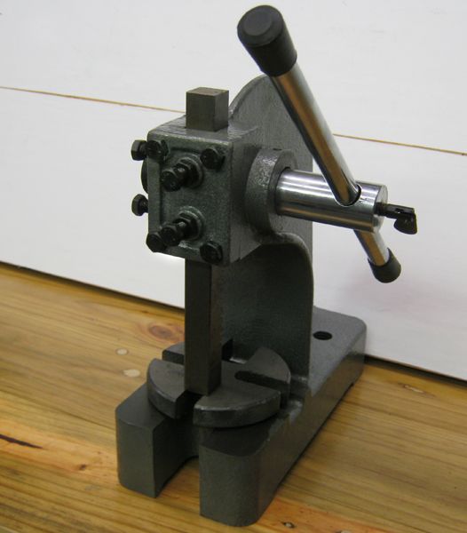
For anyone wondering what I got, the main casting was very rough and would not sit level on the bench without rocking.
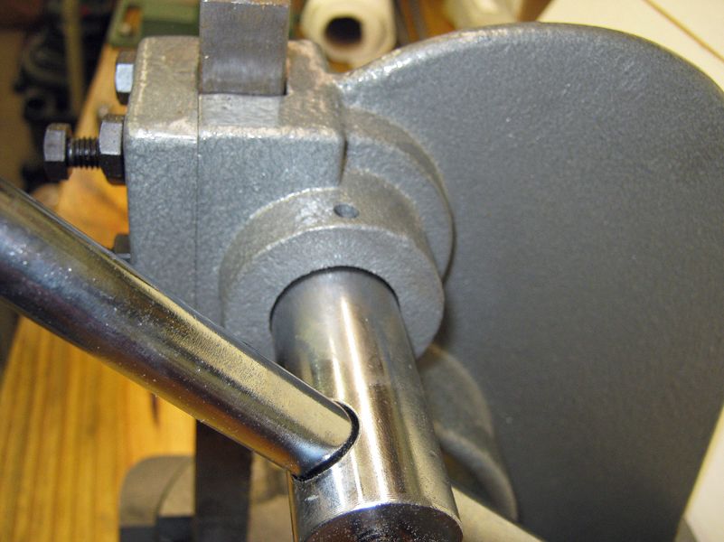
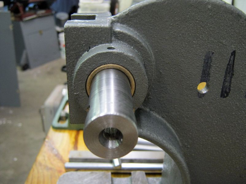
The Main shaft/pinion was very loose in the casting, relying on the gear mesh with the rack/ram and the adjusting screws to take up the slack
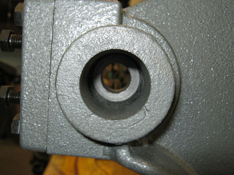
I don't know if you can really see it in this photo, but the bore in the casting was egg-shaped and not aligned with the axes of use.
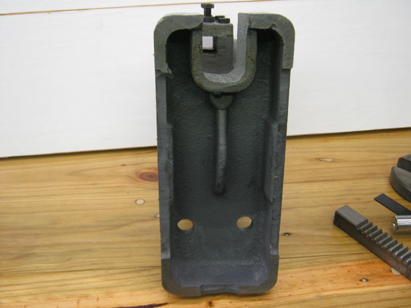
Just FYI, but the pivot pin for the rotating plate on the base is located strangely: Is this by design?
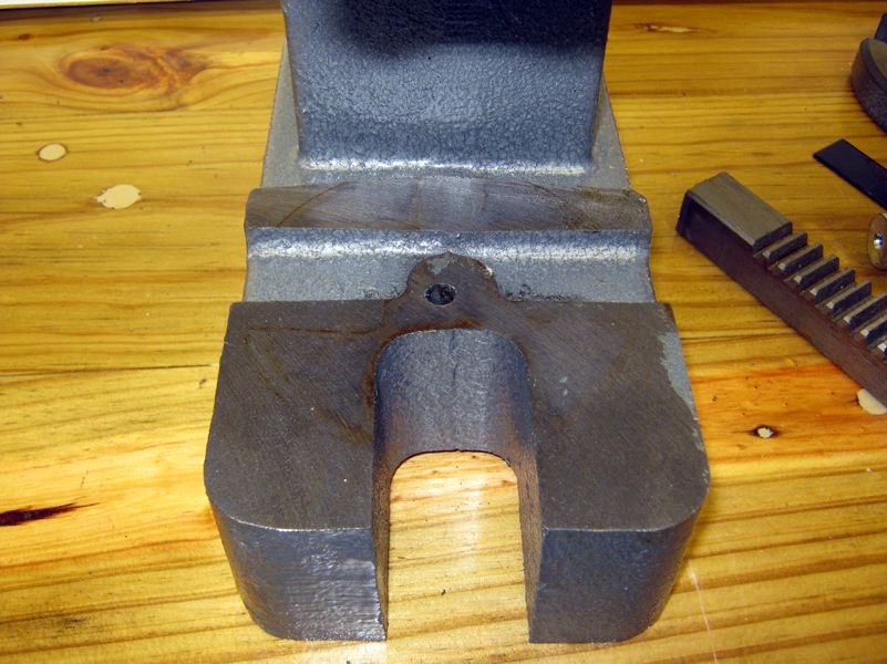
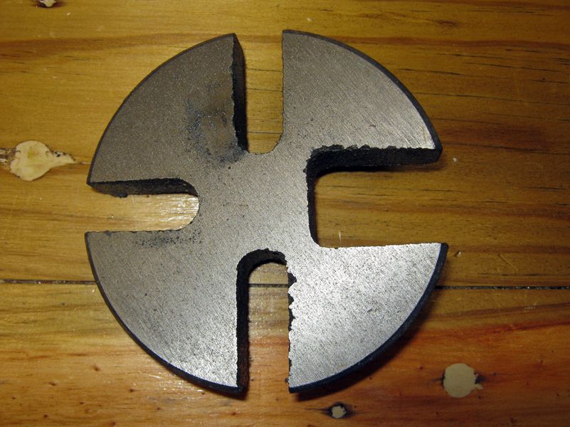
Also FYI, the rotating plate. I can't think of anything I would want to press where any of the four apertures provided would fit
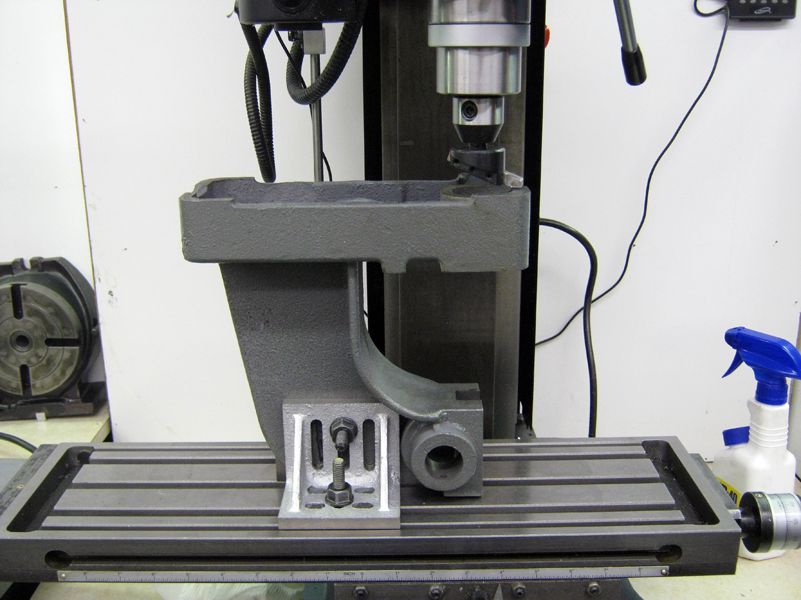
I decided to clean up the casting while contemplating the parts I needed to make or modify. I started with the "feet" first, needing to get it to sit level on the bench. This part drug on, as I wrestled with the problems of working with a casting. As others have said, many hours spent on lining up and clamping for a few minutes of machining.
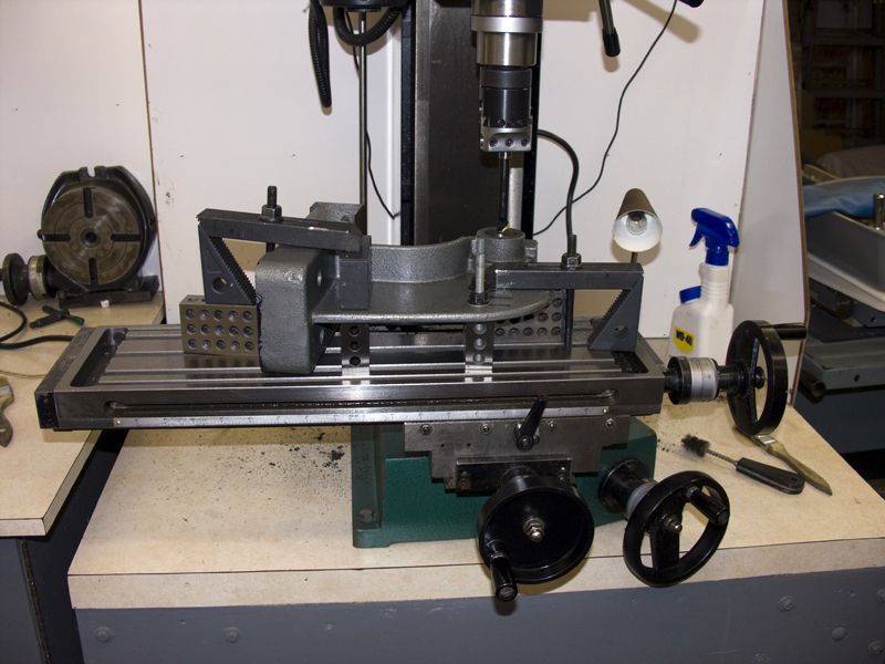
After a few days of measuring and staring at things, I ended up drilling two holes in the back web of the thing, the spacing matching some of the holes in some of my angle plates and 1-2-3 blocks. With the casting sandwiched between two angle plates that could be clamped to the outer two T-slots in the mill table and the top of the main web in the middle T-slot for clearance, I was able to present the base to a fly cutter in the milling head.
I was prepared for a lot of chatter and a re-think before I went forward at this point, but I found that the cast iron machined very easily and that with care the dreaded chatter could be avoided. It was messy, like all cast iron, but not as bad as I was prepared for. I do need to mention that I put a large, clear plastic shield between the work and myself while running and that I always wear full-face safety headgear. I take photos after setup to show things clearly, but please be assured safety is in my mind.
The cutter was a brazed-carbide lathe toolbit of the type designed for cast iron. For work like this, I prefer this option to endmills. I think the fly cutter also works surprisingly well on cast iron if you take it slowly.
With all but the X travel on the mill secured, with slow speed and very small cuts, I was able to gradually sneak up on making things more even. I would mill a very little, then remove the assembly and recheck and remeasure with the piece on my surface plate, also occasionally using files and Dykem to check my progress.
By the time I had the base sorted, I had decided how I would continue with the project, making the press head function for tapping and for light pressing. The alignment and fit of the main bore needed to be addressed, and I wanted a smooth-rolling action of the pinion/shaft assembly. I measured the moving parts and the bores, and determined that I could use ready-made bronze sleeve bearings available for a few dollars. I also ordered an extended tap handle that could be modified to fit my vision for this project.
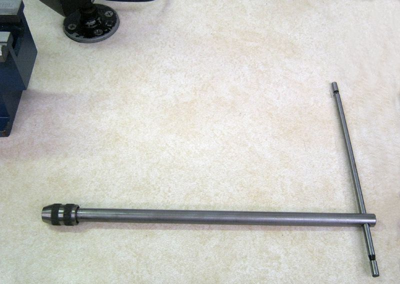
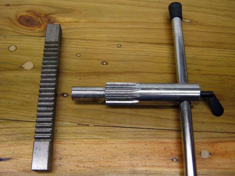
The stock ram/rack and pinion/shaft assemblies.
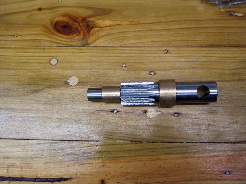
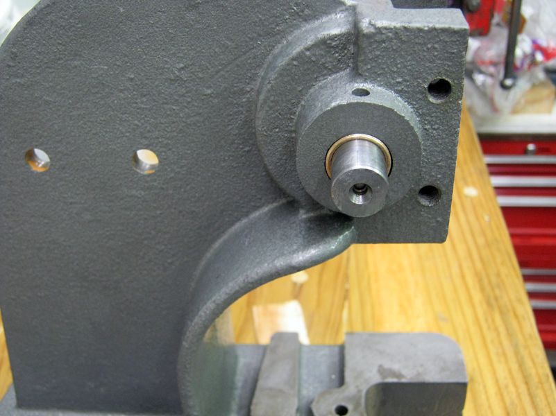
The pinion/shaft after turning to fit the IDs of the bearings. This picture shows the "first" version. I later found out that I needed to turn the shaft down further into the gear portion to make things fit better. I considered modifying the bearings instead, but I found that the metal of the shaft turned pretty well, but seemed to have some inconsistent areas I couldn't clean up. "Blacksmith Engineering": I made the fit so it "felt" right. Anything I do to this thing has gotta be better than what I started with.
After getting the shaft and bearings ready, it was time to address the fit and alignment of this assembly to the casting. This is something I spent a great deal of time doing, and resulted in more than one setup which was later torn down and rethought. In the end, I ended up with the following:
The main securing area is the two bolts through the casting and 1-2-3 block and down to the T-slots. The two other clamps pinched the main casting web against 1-2-3 blocks and made sure that everything wouldn't shift or vibrate during boring. The boring bar was chosen to bore the lower, smaller part of the casting, then the boring head was readjusted to do the larger, upper bearing bore. Measuring and setting-up to make sure this pair of bores would be aligned took hours. You can't see them, but there are shims here and there to tweak everything.
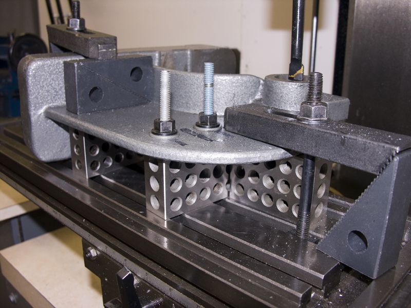
Taking it very slow and carefully, each bore was carefully done, measuring with Telescoping gages at first, then raising the mill head and using the shaft and bearing assembly to check the fit. This particular cast iron cut very well and smoothly.
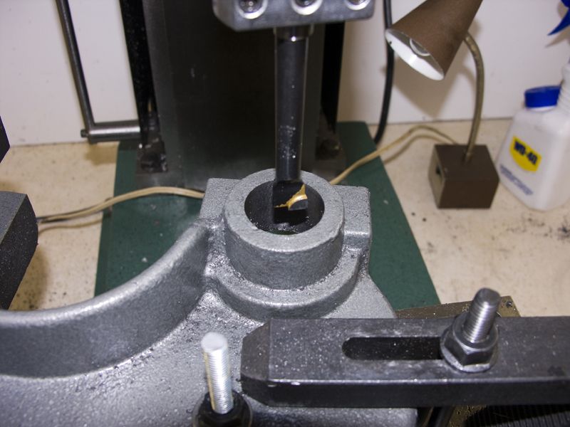
The bores are about 0.001 larger than the bearing ODs, and I used loctite to secure the bearings.
I have to admit that the boring of the casting kept me worrying until it was over, then with some relief I moved on to deciding how to make a new rack assembly that would incorporate the tapping shaft. A piece of 1 x .75 aluminum bar fit well, but would require me to make a new front for the head: Not a complex piece to make.
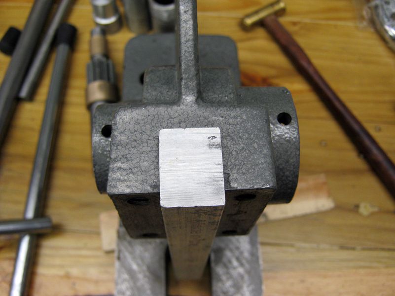
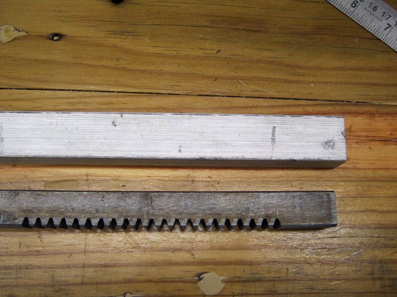
Next step was to cut teeth on a section of the aluminum bar. After worrying over special cutters and elaborate scenarios, I ended up just cutting teeth with my bandsaw and finishing the teeth with files. It probably took less time to cut and file the teeth than I spent worrying about special milling techniques. The photo shows the mid-process progress, much better looking when done.
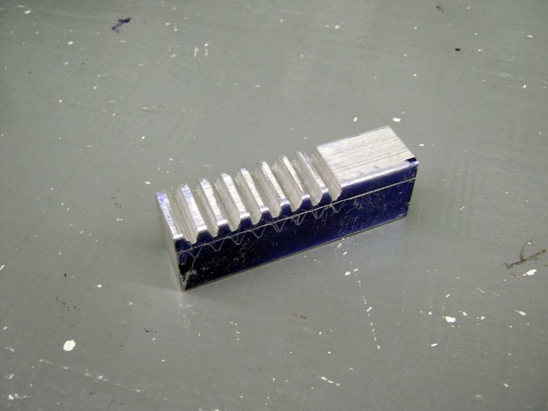
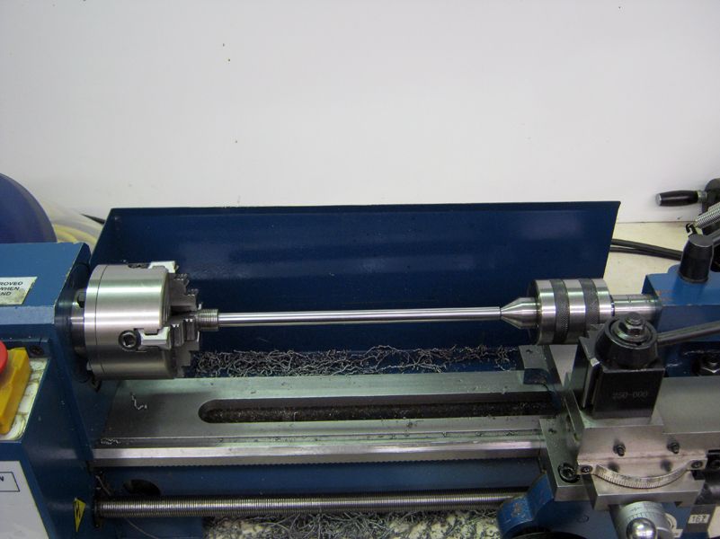
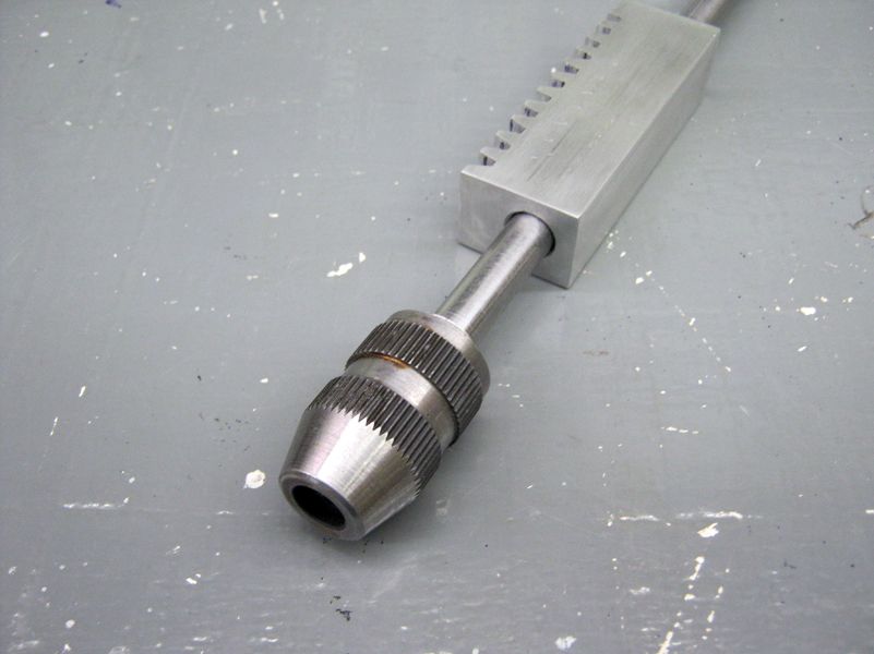
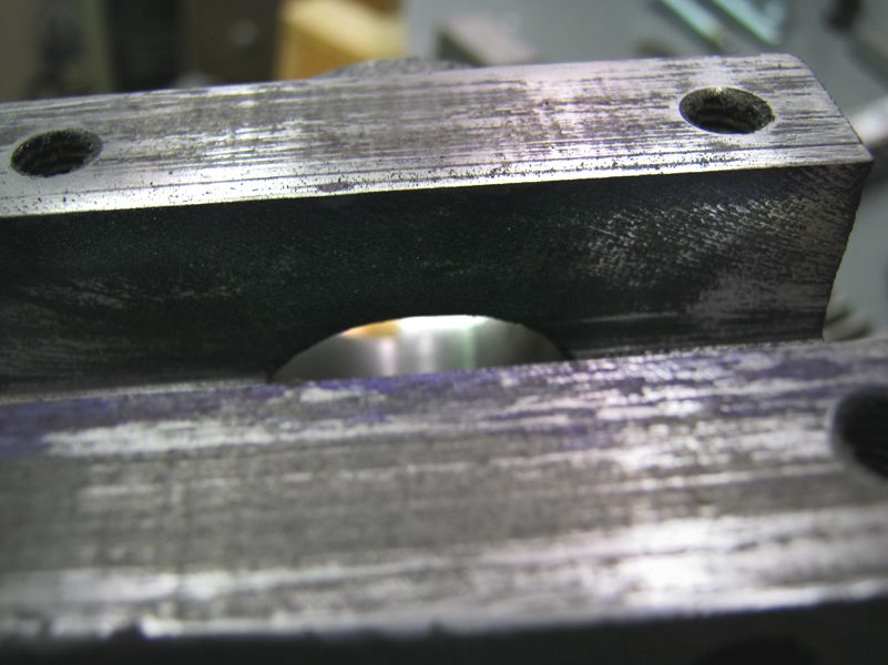
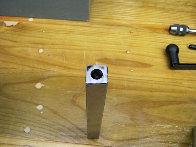
After drilling and reaming a 3/8-inch hole through the new rack, I moved to the lathe and turned down the shaft of the extended tap handle to fit the hole. I took special care to indicate and center the part, using the four-jaw chuck on one end and a revolving center on the other. the steel of this part turned very well, and finishing was done by sanding with 220, then 400, then 600 grits. (Please note that the shaft IS centered in the block, the photo just makes it look off-center.)
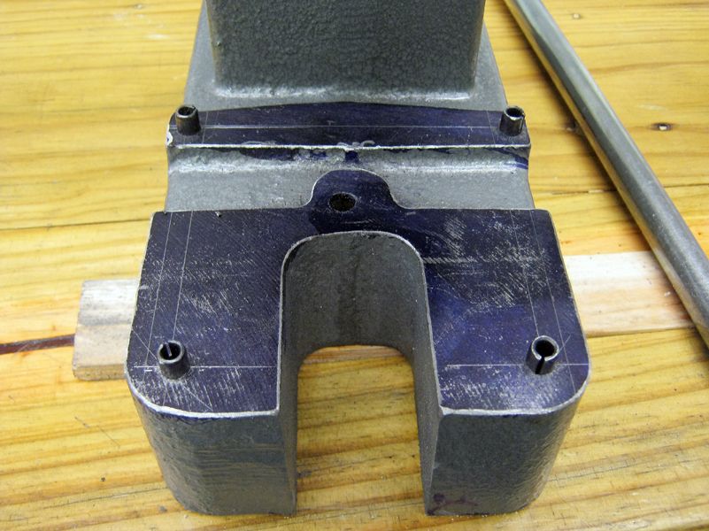
The new front piece was made from a block of 1018 steel I had, only requiring a slot cut through on the back side, then the front edges made neat with a corner-rounding endmill and some filing.
After making that piece, alignment and function was improved by working on the casting inside its slot, Milling was attempted, but I got nervous and reverted to filing, using Dykem to help me keep track of where I was going.

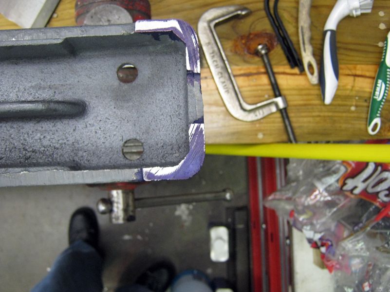
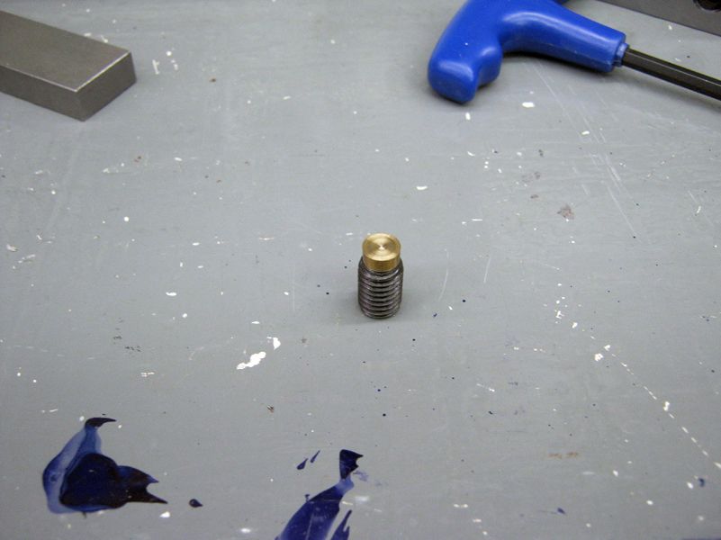
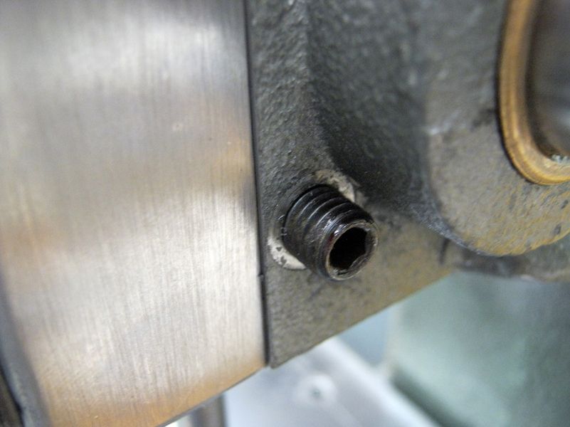
To make adjustment to perpendicular possible (and to avoid attempting more machining that I thought could cause more damage than good), I made up some adjustment screws from Metric socket setscrews. I heated them to cherry, then let them air cool (I think as adjustment screws, I can get by without their original hardening, and I can always replace them if this doesn't work)
After cooling, I drilled them from the bottom, then made brass ends which I fixed into place with loctite.
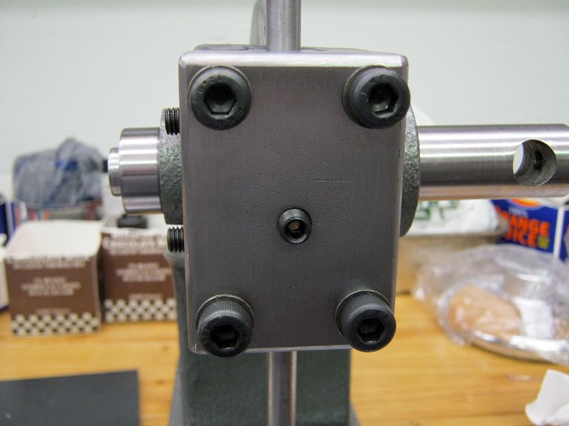
Besides the two original adjustment screw locations on the left side, I put one on the front and added one on the right side -- bottom.
For a work stage, I had a piece of 1/4-in. steel which I cut and squared up, then drilled four 1/4-in. holes to line it up to the base. Not knowing for sure the final use and deciding that the stage might evolve into a series of workholding ideas, I only rounded the corners for safety and decided to perch it on the base with four roll pins for now: This is another part which could be remade without too much trouble.
http://i1215.photobucket.com/albums/cc509/partbuilder/Press-Tapper%20Buildlog/Press-Tapper_Buildlog_27.jpg[/IMG
For tapping, the plan is to use another piece of 1/4-in. plate to clamp down parts, then move it around under the head and secure it by clamping on the edges to the "stage" plate. This other plate will be finished later.
[IMG]http://i1215.photobucket.com/albums/cc509/partbuilder/Press-Tapper%20Buildlog/Press-Tapper_Buildlog_28.jpg
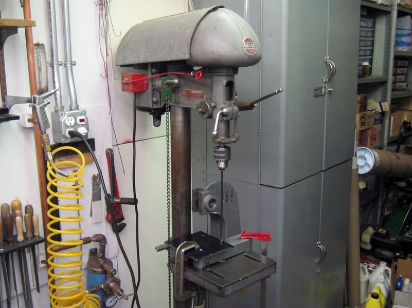
I used a transfer punch to transfer the holes to the cast iron of the main casting, then moved everything to my ancient Delta drill press so I could use a long drill to drill through the holes of the stage plate while clearing the sides of the casting at the same time: It just barely fit.
I returned to the original ram/rack at this point. Since this press may still be used for extremely-light pressing, I decided to drill a 3/8-in. hole in one end of the ram (I checked to make sure that they are interchangeable) for possible tools I might make from drill rod.
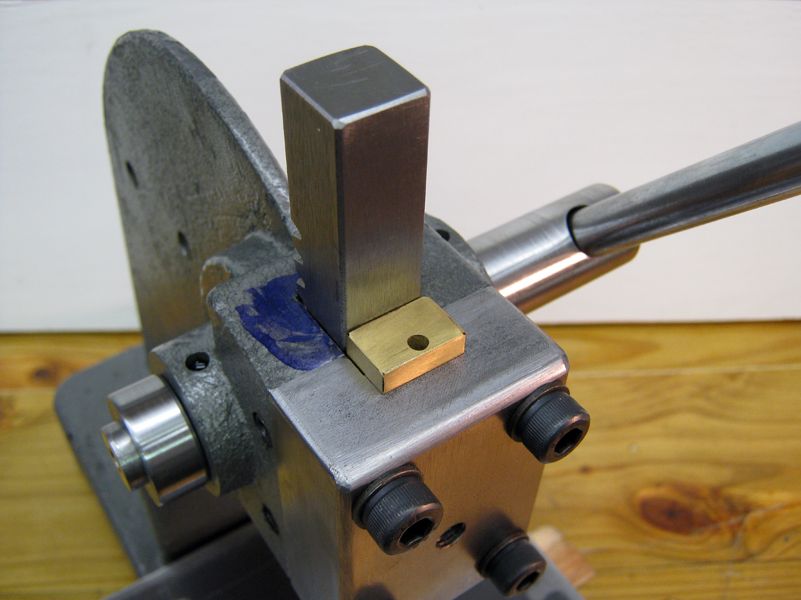
I made a brass L-shaped drop-in spacer to retain the press rack when in use. By pulling this out first, the rack can be moved toward the front of the unit and lifted out of the press.
For the tapping shaft, I milled the free end to a 5/16 hex via the quick-and-dirty method of holding in a hex collet block and turning it to cut each flat face. this allowed me to use 5/16 sockets to attach handles of different types.
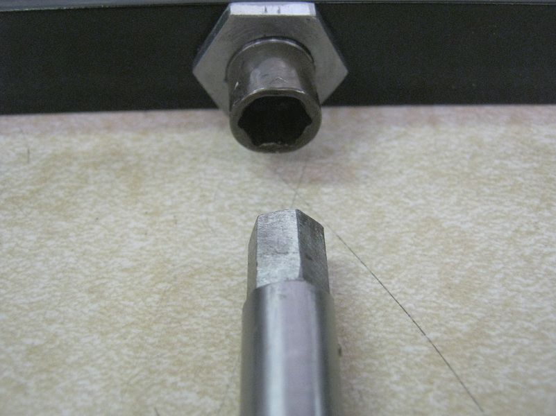
I made a short T-handle by silver-soldering a knurled bar to a modified socket and a longer bar handle with two plastic spinner knobs that are held by nuts to a socket with outside threads.
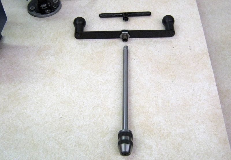
Final cleanup with some files and dremel for the time being. I won't paint it until I've played with it and decide I'm really done.
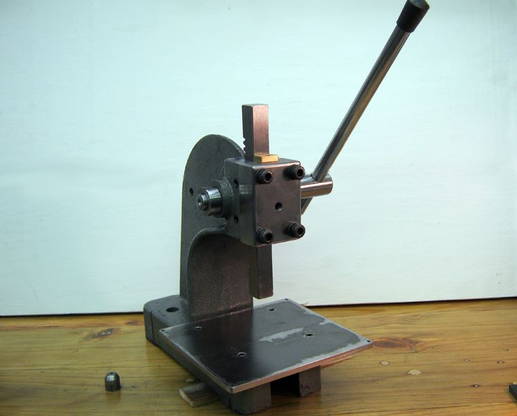
As it stands:
Tapper Mode:
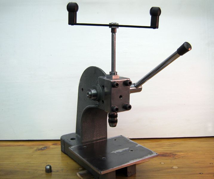
Press Mode:
Conclusion: I don't know whether the time involved in this was worth it in terms of the final result. Perhaps more changes from where I am now will be done. I do think I got some good practice with machining a large, very rough casting.
--ShopShoe
A visit to HF and accumulated discounts resulted in the purchase of this 1/2-ton arbor press for less than twenty dollars. I really wanted the next larger size, but decided to go ahead with this. Perhaps I could do something about the limited vertical space. Anyway, I don't want to take up a lot of shop space for this item and I want to do this without spending a lot of money. I could buy the "real" press or tapping stand later if this doesn't work.
For anyone wondering what I got, the main casting was very rough and would not sit level on the bench without rocking.
The Main shaft/pinion was very loose in the casting, relying on the gear mesh with the rack/ram and the adjusting screws to take up the slack
I don't know if you can really see it in this photo, but the bore in the casting was egg-shaped and not aligned with the axes of use.
Just FYI, but the pivot pin for the rotating plate on the base is located strangely: Is this by design?
Also FYI, the rotating plate. I can't think of anything I would want to press where any of the four apertures provided would fit
I decided to clean up the casting while contemplating the parts I needed to make or modify. I started with the "feet" first, needing to get it to sit level on the bench. This part drug on, as I wrestled with the problems of working with a casting. As others have said, many hours spent on lining up and clamping for a few minutes of machining.
After a few days of measuring and staring at things, I ended up drilling two holes in the back web of the thing, the spacing matching some of the holes in some of my angle plates and 1-2-3 blocks. With the casting sandwiched between two angle plates that could be clamped to the outer two T-slots in the mill table and the top of the main web in the middle T-slot for clearance, I was able to present the base to a fly cutter in the milling head.
I was prepared for a lot of chatter and a re-think before I went forward at this point, but I found that the cast iron machined very easily and that with care the dreaded chatter could be avoided. It was messy, like all cast iron, but not as bad as I was prepared for. I do need to mention that I put a large, clear plastic shield between the work and myself while running and that I always wear full-face safety headgear. I take photos after setup to show things clearly, but please be assured safety is in my mind.
The cutter was a brazed-carbide lathe toolbit of the type designed for cast iron. For work like this, I prefer this option to endmills. I think the fly cutter also works surprisingly well on cast iron if you take it slowly.
With all but the X travel on the mill secured, with slow speed and very small cuts, I was able to gradually sneak up on making things more even. I would mill a very little, then remove the assembly and recheck and remeasure with the piece on my surface plate, also occasionally using files and Dykem to check my progress.
By the time I had the base sorted, I had decided how I would continue with the project, making the press head function for tapping and for light pressing. The alignment and fit of the main bore needed to be addressed, and I wanted a smooth-rolling action of the pinion/shaft assembly. I measured the moving parts and the bores, and determined that I could use ready-made bronze sleeve bearings available for a few dollars. I also ordered an extended tap handle that could be modified to fit my vision for this project.
The stock ram/rack and pinion/shaft assemblies.
The pinion/shaft after turning to fit the IDs of the bearings. This picture shows the "first" version. I later found out that I needed to turn the shaft down further into the gear portion to make things fit better. I considered modifying the bearings instead, but I found that the metal of the shaft turned pretty well, but seemed to have some inconsistent areas I couldn't clean up. "Blacksmith Engineering": I made the fit so it "felt" right. Anything I do to this thing has gotta be better than what I started with.
After getting the shaft and bearings ready, it was time to address the fit and alignment of this assembly to the casting. This is something I spent a great deal of time doing, and resulted in more than one setup which was later torn down and rethought. In the end, I ended up with the following:
The main securing area is the two bolts through the casting and 1-2-3 block and down to the T-slots. The two other clamps pinched the main casting web against 1-2-3 blocks and made sure that everything wouldn't shift or vibrate during boring. The boring bar was chosen to bore the lower, smaller part of the casting, then the boring head was readjusted to do the larger, upper bearing bore. Measuring and setting-up to make sure this pair of bores would be aligned took hours. You can't see them, but there are shims here and there to tweak everything.
Taking it very slow and carefully, each bore was carefully done, measuring with Telescoping gages at first, then raising the mill head and using the shaft and bearing assembly to check the fit. This particular cast iron cut very well and smoothly.
The bores are about 0.001 larger than the bearing ODs, and I used loctite to secure the bearings.
I have to admit that the boring of the casting kept me worrying until it was over, then with some relief I moved on to deciding how to make a new rack assembly that would incorporate the tapping shaft. A piece of 1 x .75 aluminum bar fit well, but would require me to make a new front for the head: Not a complex piece to make.
Next step was to cut teeth on a section of the aluminum bar. After worrying over special cutters and elaborate scenarios, I ended up just cutting teeth with my bandsaw and finishing the teeth with files. It probably took less time to cut and file the teeth than I spent worrying about special milling techniques. The photo shows the mid-process progress, much better looking when done.
After drilling and reaming a 3/8-inch hole through the new rack, I moved to the lathe and turned down the shaft of the extended tap handle to fit the hole. I took special care to indicate and center the part, using the four-jaw chuck on one end and a revolving center on the other. the steel of this part turned very well, and finishing was done by sanding with 220, then 400, then 600 grits. (Please note that the shaft IS centered in the block, the photo just makes it look off-center.)
The new front piece was made from a block of 1018 steel I had, only requiring a slot cut through on the back side, then the front edges made neat with a corner-rounding endmill and some filing.
After making that piece, alignment and function was improved by working on the casting inside its slot, Milling was attempted, but I got nervous and reverted to filing, using Dykem to help me keep track of where I was going.
To make adjustment to perpendicular possible (and to avoid attempting more machining that I thought could cause more damage than good), I made up some adjustment screws from Metric socket setscrews. I heated them to cherry, then let them air cool (I think as adjustment screws, I can get by without their original hardening, and I can always replace them if this doesn't work)
After cooling, I drilled them from the bottom, then made brass ends which I fixed into place with loctite.
Besides the two original adjustment screw locations on the left side, I put one on the front and added one on the right side -- bottom.
For a work stage, I had a piece of 1/4-in. steel which I cut and squared up, then drilled four 1/4-in. holes to line it up to the base. Not knowing for sure the final use and deciding that the stage might evolve into a series of workholding ideas, I only rounded the corners for safety and decided to perch it on the base with four roll pins for now: This is another part which could be remade without too much trouble.
http://i1215.photobucket.com/albums/cc509/partbuilder/Press-Tapper%20Buildlog/Press-Tapper_Buildlog_27.jpg[/IMG
For tapping, the plan is to use another piece of 1/4-in. plate to clamp down parts, then move it around under the head and secure it by clamping on the edges to the "stage" plate. This other plate will be finished later.
[IMG]http://i1215.photobucket.com/albums/cc509/partbuilder/Press-Tapper%20Buildlog/Press-Tapper_Buildlog_28.jpg
I used a transfer punch to transfer the holes to the cast iron of the main casting, then moved everything to my ancient Delta drill press so I could use a long drill to drill through the holes of the stage plate while clearing the sides of the casting at the same time: It just barely fit.
I returned to the original ram/rack at this point. Since this press may still be used for extremely-light pressing, I decided to drill a 3/8-in. hole in one end of the ram (I checked to make sure that they are interchangeable) for possible tools I might make from drill rod.
I made a brass L-shaped drop-in spacer to retain the press rack when in use. By pulling this out first, the rack can be moved toward the front of the unit and lifted out of the press.
For the tapping shaft, I milled the free end to a 5/16 hex via the quick-and-dirty method of holding in a hex collet block and turning it to cut each flat face. this allowed me to use 5/16 sockets to attach handles of different types.
I made a short T-handle by silver-soldering a knurled bar to a modified socket and a longer bar handle with two plastic spinner knobs that are held by nuts to a socket with outside threads.
Final cleanup with some files and dremel for the time being. I won't paint it until I've played with it and decide I'm really done.
As it stands:
Tapper Mode:
Press Mode:
Conclusion: I don't know whether the time involved in this was worth it in terms of the final result. Perhaps more changes from where I am now will be done. I do think I got some good practice with machining a large, very rough casting.
--ShopShoe