IMPACT CYLINDER

Home Model Engine Machinist Forum

Help Support Home Model Engine Machinist Forum:

This site may earn a commission from merchant affiliate links, including eBay, Amazon, and others.

Brian Rupnow

Design Engineer
Project of the Month Winner
Joined
May 23, 2008
Messages
15,002
Reaction score
8,299
Location
Barrie, Ontario, Canada
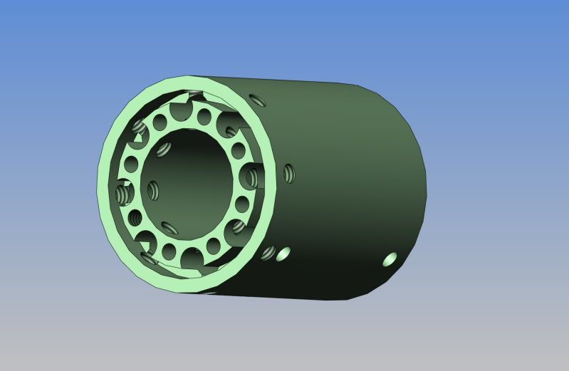
This is all Chucks fault!!! He's got me thinking about this, and I can't get it out of my head. This is an air cylinder that has a lot in common with a cannon. It is horribly dangerous, and loud, and may have no practical application in "model world".---BUT---If you could use it on an air powered hit and miss engine like Chuck has designed, it would make an awesome hit and miss engine. Basically, what happens is that when air is applied to the cap end of the cylinder, it pressurizes all of the air chambers built into the cylinders body. A small amount of this air is bled off into the top of the cylinder itself to get the piston to start moving. I have shown an adjustment screw to control how much air bleed. The piston begins to move, and after about 0.100" of travel, the piston skirt uncovers the 8 radial "air dump" holes in the cylinder wall. All of the pressure stored in those chambers rushes into the cylinder and the piston takes off at about 3000 miles per hour. This type of cylinder is not used to power rotating machinery, but is used to drive some type of Impact device, like nail guns, jack hammers, etcetera. However---If you could build a model hit and miss engine with a large enough pair of flywheels to soak up that tremendous shot of kinetic energy it would be awesome!!! These things are very dangerous, and if someone builds one and manages to hurt or kill himself or anybody else with it, I take no responsibility. Remember, there are plans on the internet to build an atomic bomb also, but its not recomended to build one in your home workshop!!! Since I am somewhat intrigued with this (at least enough to spend a morning designing instead of playing outside in the sunshine), I MAY build one myself.----Brian
ASSYBRIANIMPACTCYL.jpg


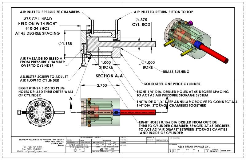
View attachment ASSY BRIAN IMPACT CYL..PDF
 
This is a picture of the cylinder with the head removed. You can see the 8 #10-24 tapped holes which hold the cylinder head on, the eight 1/4" dia. x 1.75" deep drilled holes which act as air storage chambers, and the annular groove which lets air flow freely between all of the air storage chambers. Since the 8 "dump" holes have to be drilled thru both outer and inner walls of the cylinder, they are then tapped and a #10-24 set screw is used to plug each of the holes in the outer wall. (Due to some of the mysteries inherent in my 3D cad software, the threads aren't showing up in the eight #10-24 tapped holes which hold the cylinder head on.)
BRIANIMPACTCYLINDER.jpg
 
Looks like your about a third of the way to a gatling air nailer. ;D
I suppose you could try and drive some type of wobble plate to turn it into rotary motion?
 
Would make a good nut cracker ;D

I wonder if the large flywheels could accelerate fast enough to keep up with one burst from the piston? would want a substantial keyway to stop the crank turning within the flywheel.

J
 
Actually, I'm hoping to get Chuck involved here. He is very knowledgeable, and I'm sure there are things we can collaborate on to make this more engine friendly. One of the things I see is that it doesn't have to be double acting as shown. If it drove a pair of heavy flywheels on the outstroke, and then the inlet valve which lets air into the air chamber end was closed, the inertia of the flywheels would take care of the return stroke. Secondly, in order to ensure that ALL of the air in the air chambers and upper cylinder is released perhaps it would benefit from a second ring of "dump" holes arrayed around the bottom of the cylinder so that when the piston reached close to BDC any remaining air pressure would be vented to atmosphere. If the cylinder didn't have to be double acting, then the piston rod could be a pivotting connection at the piston, thus enabling the piston rod to be directly connected between the piston and the crank throw, acting like a conventional connecting rod and letting the cylinder remain stationery instead of having to pivot. The valve timing would have to be more advanced than in a conventional engine, to allow enough time for the air pressure to build up in the pressure chambers before it actually "fired" the piston--Damn---I'm right full of ideas---(or something!!!)
 
Looks interesting, but I'm gonna have to study the drawings some. Assuming a compressor pressure of 100 PSI, the force applied on top of the piston for various sizes would be as follows:

Diameter Force

1.25" 123 pounds
1.00" 79 pounds
0.75" 45 pounds
0.50" 20 pounds

I'm assuming there are no inertial forces from the air so it would be a straight calculation of air pressure against area of piston top.

My latest, air powered hit n miss engine uses somewhat the same principle. However, the air has to travel from the valve to the cylinder through a 3/16" passage and 2, 90 degree angles, so I'm sure there is a big loss in turbulence and air resistance. There's no question that Brian's design would provide a much greater kick to the flywheel. However, some kind of valve would be required to shut off the air supply for the return stroke and for subsequent miss strokes for hit n miss operation. I'm thinking a sleeve around the outer wall of the internal cylinder would work, similar to the palm nailer. More to come...

Chuck
 
Chuck---Great minds think alike----I have been pondering this afternoon while doing other chores. The current design as shown depends on the air bleed from the pressure chamber to start the piston moving. However, as you, I was thinking about the possibility of a sleeve valve around the "Dump" holes that was mechanically activated. This would take that hesitation out of the initial piston movement, and be more "positive". The big thing with this type of cylinder doesn't seem to be as much a factor of pressure as it does flow. The fact that the surrounding chamber is pressurized and then dumped into the cylinder from a lot of holes all at once seems to be the bit of magic.
 
Doesn't this just perform the same function as a steam chest ? The only apparent functional difference is the cascading valve effect as the piston moves.

Am I missing something here ?. Please don't take this as a negative comment, just trying to find out if there is some other reason for doing it this way.

I am quite interested in the nuances of compressed gas engines, and their differing valve techniques. On a slightly different track, if a cylindrical 'air' chest was used its volume could be changed with a set piston to vary the power output of the engine.

Always interested to read your posts chuck, many thanks.

Best Regards

picclock
 
A stepped cylinder with greatly differing large and small diameters has been used for High Energy Rate Forming (HERF). The gas in this case being Nitrogen, coming straight from the bottle with NO regulator/pressure reducing valve. This means many thousands of psi. Relatively large bore and very heavy tubing to get the gas to the cylinder to maximise flow. Needless to say the forces and accelerations were awesome and the shock could be felt through the building floor when fired. As I recall, the cylinder was triggered by suddenly releasing the balancing pressure on the small side of the cylinder, which virtually instantaneously allowed the gas at full pressure to reach the full diameter of the large side. Imagine nail guns X 1000 at least. This is scarey stuff.
 
picclock said:
Doesn't this just perform the same function as a steam chest ? The only apparent functional difference is the cascading valve effect as the piston moves.

Am I missing something here ?. Please don't take this as a negative comment, just trying to find out if there is some other reason for doing it this way.

I am quite interested in the nuances of compressed gas engines, and their differing valve techniques. On a slightly different track, if a cylindrical 'air' chest was used its volume could be changed with a set piston to vary the power output of the engine.

Always interested to read your posts chuck, many thanks.

Best Regards

picclock

I was wondering if the same effect could be achieved by making the steamchest much larger. This would give a large VOLUME of pressurized air, and if built along the lines of a conventional steamchest, the pressure inside the chest would serve to keep the slidegate tight against the cylinder to prevent leakage. The trouble I find with ring style slidevalves is that they tend to leak like crazy.


cfellows said:
Looks interesting, but I'm gonna have to study the drawings some. Assuming a compressor pressure of 100 PSI, the force applied on top of the piston for various sizes would be as follows:

Diameter Force

1.25" 123 pounds
1.00" 79 pounds
0.75" 45 pounds
0.50" 20 pounds

I'm assuming there are no inertial forces from the air so it would be a straight calculation of air pressure against area of piston top.

My latest, air powered hit n miss engine uses somewhat the same principle. However, the air has to travel from the valve to the cylinder through a 3/16" passage and 2, 90 degree angles, so I'm sure there is a big loss in turbulence and air resistance. There's no question that Brian's design would provide a much greater kick to the flywheel. However, some kind of valve would be required to shut off the air supply for the return stroke and for subsequent miss strokes for hit n miss operation. I'm thinking a sleeve around the outer wall of the internal cylinder would work, similar to the palm nailer. More to come...

Chuck
chuck---I don't think it has as much to do with the force created by direct pressure as it does with the kinetic force created by the ACCELERATION of the piston. Its the difference in holding 10 pounds of something in your hand and being hit in the hand by something that weighs 10 pounds that is travelling 50 miles an hour. Its still only 10 pounds, but what a difference!!!
 
Brian Rupnow said:
I was wondering if the same effect could be achieved by making the steamchest much larger. This would give a large VOLUME of pressurized air, and if built along the lines of a conventional steamchest, the pressure inside the chest would serve to keep the slidegate tight against the cylinder to prevent leakage. The trouble I find with ring style slidevalves is that they tend to leak like crazy.

Brian, I recall from somewhere in my past learnings that the main reason locomotives went to a piston valve was that very high pressures created a lot of friction in slide valves and the wear rate was too great. I have to agree with you though, that my experience in attaining a good seal with piston valves has been less than satisfactory.

Chuck
 
Here is my current thinking on his. If one were to make a single acting cylinder, with two LARGE VOLUME steam chest on opposing sides I think that would do it. The steam chests would act as pressure reservoirs, the slide valve would shuttle back and forth between a set of fairly large dump holes in each side of the cylinder ---which would serve to dump all of the pressurized air directly into the cylinder to drive it on the outstroke. The rod (or rods) that drive the slide valve could be driven off two cams running in synchronization or one long cam.---It would be designed so that at the opposite end of the slide valve stroke it uncovered holes which vented to atmosphere because the other end of the cylinder would be "'open". (assuming the return stroke was handled by the inertia of the spinning flywheels), and the "dump" holes would also be also vented to exhaust while the slide valve was in that position.
 

Latest posts

Back
Top