How To Mill External Profile

Home Model Engine Machinist Forum

Help Support Home Model Engine Machinist Forum:

This site may earn a commission from merchant affiliate links, including eBay, Amazon, and others.

JDLaCoss

Member
Joined
Nov 18, 2012
Messages
15
Reaction score
2
Hi all!

I've been hovering around here for a long time, but I think I'm finally ready to start BUILDING something. I have a small amount of engineering background, but no real machining experience. So why not start with something easy like the Bernay!? ;) Actually, the individual pieces don't look too difficult and I have already started with some of the simple pieces like the valve linkage. Now to the question:

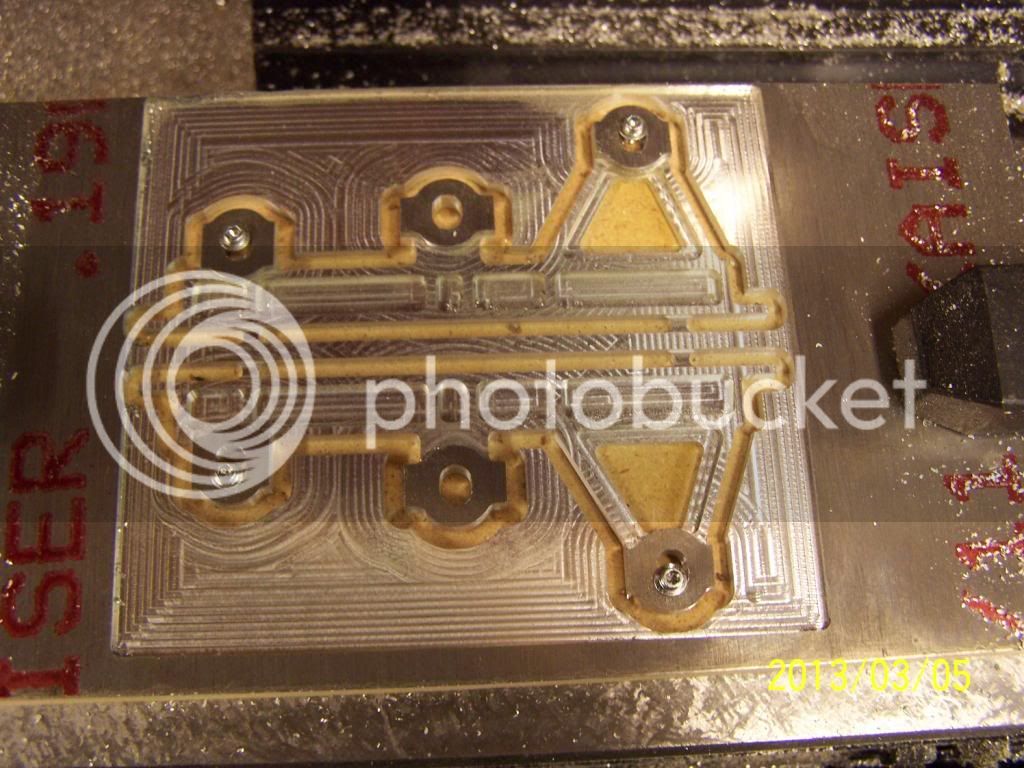
How do you normally hold material when you are cutting an external profile such as the valve links?

The way I have been cutting them is by facing to the proper thickness, drilling the through-holes, machining a fixuture to fit, then bolting the piece down using the internal holes. This works very well, but it leads to making a fixture for nearly every part. I don't mind doing that, but is there a more efficient method? What about on larger pieces?

If it makes any difference, I am using a benchtop Prolight 1000 mill. I have a pretty decent 4" vise and the typical T-Slot hold-downs, but not a lot else. If there is something else I should be looking for, I am always open to shopping for new tools! :-D

Thanks in advance for sharing your wisdom!

Jason
 
I assume that your mill is a small cnc machine. Here are some of the techniques I've used.

1) Use thicker material than the finished piece, with enough extra to clamp in the vise. After milling the profile, turn it over and use an endmill to remove the extra thickness. If the profile is able to be held in the vise all is well. If the profile is an odd shape, you can use soft jaws in the vise to mill a pocket that matches the profile (mirror image).

2) Leave holding tabs in the profile and mill through. Then the tabs can be cut through and the stub filed/sanded. This works well with parts cut from sheet material.

3) Glue the stock down to a flat plate that's held in the vise. Use light cuts, and then heat to release the glue. 2-sided tape can also work.
 
Thanks for the insight. You are correct in assuming that I am using a CNC. I have tried machining the thicker material then flipping, and that seems to work alright. I've had some issue getting zeroed properly again (close, but not dead on) after flipping. Somehow I always seem to be off just a few thou. I have also heard of using double-stick tape,but I guess I didn't really trust it to hold. I'll have to give it a shot. Thanks again!
 
With the machine and flip method you generally want to machine to full depth and upon flipping only face/chamfer.

As KVOM said the best for part being on center is to mill soft jaws in the vise to the part profile. Use the same X0 Y0 for soft jaw and part.

Question. Do the small cnc mills, ie. hobby size, have multiple work piece coordinates like G54, G55 and so on?
 
Just yesterday my cnc mill spent 4 hours machining these little side plates for a donkey winch I am building. I did all the internal pockets first. then did a fake tool change so I could put the 4 screws in before doing the final outside profile. Left 2 tabs on the bottom of each plate that were sawed off and filed flat after . Worked out great. Spindle speed is low for the size of end mill so only 10IPM feed.

Dave


000_0601_zpsae77f0ca.jpg
 
Is there some reason for all that milling outside the parts?

I'd have suggested defining a single pocket that included both parts and mill that to the part thickness with a larger endmill. Then pocket and insert the screws, finally finish the outer profile.

Flipping the part without using soft jaws you want to use dowel pins for alignment rather than tapped holes. There is always a few thou clearance for screws.
 
There is no reason other than I could of done things differently. This was a learning process for me.

Dave
 
With the machine and flip method you generally want to machine to full depth and upon flipping only face/chamfer.

As KVOM said the best for part being on center is to mill soft jaws in the vise to the part profile. Use the same X0 Y0 for soft jaw and part.

Question. Do the small cnc mills, ie. hobby size, have multiple work piece coordinates like G54, G55 and so on?

I can't speak for all mini-mills, but my setup does support local coordinate systems like G54, G55. I am using linuxCNC which seems to have a pretty extensive set of options. I am trying to mill to depth where possible to preven alignment issues. The valve rods in particular don't allow that as they have a pocket that has to be milled from the reverse side. The end of the pocket is concentric with the rod end so it has to be aligned very carefully when flipped (Think of a connecting rod with both thicker ends and a narrow center beam.) Again, this is more of a learning opportunity for me than a real problem. Thanks for the feedback.
 
Here's a pic of the latest try at the valve links. Spent quite a bit of time learning a good way of polishing them, but feel kind of guilty about it now after having read some of the other posts. ;) Made from steel bar welding stock I found at the local hardware store. Have no idea what type, but my best guess is A36 hot roll.

On the subject of material, I have a couple of questions unrelated to the profiling. I've been looking for a good source of small quantity metal. We have a shop that sells a lot of aluminum scrap, but not much else. I've checked a couple of the online stores, but the sticker price is a bit of a shock. Thus my questions:

1) Do folks have a favorite supplier? Is one supplier better than another for a particular material (say brass vs cold roll steel vs bronze)?
2) A lot of parts are exact stock thickness (say .250"). I am concerned about purchasing exact stock that may have blemishes/dents/gouges that have no tolerance for machining when it arrives. As such, I have been pricing stock the next size over what I need to allow facing for appearance sake. This of course drives up cost. Thoughts on how to handle this? Leave the blemishes? Eat the extra cost?

I realize this has probably been covered ad nauseum. I will continue to sift through the older posts, but would appreciate any current input that might be offered up.

ValveLinks.jpg
 
Just a thought if you do try the double sided tape idea (and it does work well), is to avoid coolant in case the part comes loose. Also, with fragile parts on tape, it can be tricky to release the part, even if you soak it in solvent.

One product that works verrry well is this stuff:-

http://www.miteebite.com/products/mitee_grip_e.html

Highly recommended ;)
 
I have a steel yard not to far away from me that has hot rolled steel in all the sizes I've need for my loco. I always need to buy oversize to part dimensions. First, there is mill scale that needs to be removed, and second the edges are rounded from the rolling process.

Cold rolled steel is much closer dimensionally and can usually be used without trimming.

Most aluminum that I've bought is oversized allowing milling surfaces to dimension.
 
Just about any place that does fabrication will sell you their cutoffs and left overs. Look in the yellow pages.
 
dclark, The Mitee Grip sounds like good stuff, but the web site has no price or purchase option Where do you buy it?

JDLaCloss, those links look very nice. I am doing some very similar parts now. How did you hold them? Did you use the soft jaw method? I was at the supply place yesterday and bought some material to make a batch of jaws. Your side to side alignment looks great.
 
At 195.00 per 25' roll someone needs to buy a roll and cut it into 12" squares for resell to the hobby machinist.

Dave
 
Finish 1 edge - so it is straight, and bore a hole through the part. Line up the straight edge and then center up on the bored hole. Second side should be as good as how close you can center up.
 
dclark, The Mitee Grip sounds like good stuff, but the web site has no price or purchase option Where do you buy it?

JDLaCloss, those links look very nice. I am doing some very similar parts now. How did you hold them? Did you use the soft jaw method? I was at the supply place yesterday and bought some material to make a batch of jaws. Your side to side alignment looks great.

I milled a block into a T shape to make it easy to hold in the vise. Then I drilled and tapped holes for each of the connecting rod lengths in the block. I faced all my rod blanks to thickness, then drilled the rod-end holes to JUST fit a 4-40 screw. Once I had all the blanks ready, I remounted the block in the vise and zeroed off the bottom left corner (which I accounted for in my g-code) and screwed the blank to the fixture. Since the rods are symmetric, I simply milled one side then flipped it upside down and ran the same program again. Seems like a lot of trouble for such a simple part, but overall I am pleased with the way they turned out.

Fix2.jpg
 
When I worked for a living, we used double sided carpet tape to hold pieces on the CNC mill. Of course, it all depends what size the part is and what you are doing to it. The biggest problem was getting the part unstuck without damaging it. Worked well on thinner material, but this gave the most problems getting it unstuck without damage.

Paul.
 

Latest posts

Back
Top