Hooking up a VFD to my mill

Home Model Engine Machinist Forum

Help Support Home Model Engine Machinist Forum:

This site may earn a commission from merchant affiliate links, including eBay, Amazon, and others.

kvom

Well-Known Member
HMEM Supporting Member
Joined
Jun 4, 2008
Messages
3,285
Reaction score
630
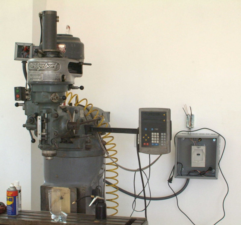
My Nema-1 enclosures arrived on Wednesday, so yesterday I took them and the VFD to school. The VFD will be housed in a 12x12x6 enclosure. The unit's dimensions are 3.94W x 5.94H x 5.06D, so plenty of room on all 4 sides for ventilation.

I used a transfer punch to locate two holes and drilled them in the back of the enclosure. The two mounting holes are .20" diameter, so probably M6 screws or 12-28. I'll be heading to the hardware store today for a trial fit.

The VFD's control panel is detachable from the unit and can be remoted via a 10-conductor cable. I decided to make a protective bezel for the control unit that will also serve as a mounting "bracket". I found a piece of 1" aluminum plate in the stock room that was just the right size. Mounted in the vise I used an end mill to true up the edges, then flycut the top.

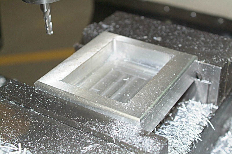
Next it was time to "calibrate" my 1/8" corner-rounding bit. In order to get a smooth rounded profile with one of these bits, the X and Z offsets from the edge need to be set fairly precisely. To get the offsets, I set the bit so that it's barrel was touching the side and zeroed the X axis on the DRO. Then lowered the quill to that the flat bottom of the mill touched the top of the plate. Then I set the mill so that it was barely cutting the corner and started to make cuts, moving the X and Z in towards the work .01" at a time. Once the bit started to cut a flat edge into the side or top, I knew that I could use the previous setting. It turned out that I needed .15" in on the X and .19" in on the Z to get a good profile. Now I was able to quickly cut the profiles on all 4 of the top edges.

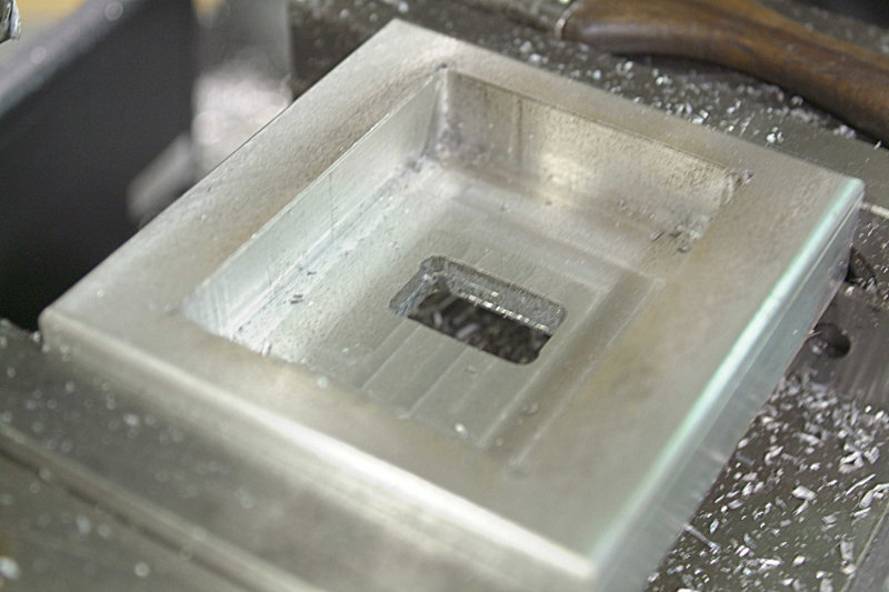
To mount the VFD panel I needed to cut a pocket into the top .65" deep. Measuring the dimensions of the panel and the final dimensions of the aluminum, I was able to calculate the DRO coordinates of each corner. I used a center drill to mark these before cutting; in theory this was unnecessary but I didn't want to mess up the work I;d already done. Having verified that the panel fit neatly within the 4 marked points I cut the pocket first with a 1/2" 2-flute end mill. Of course, I needed to set the DRO coordinates for the corners .25" inside.

My instructor indicated that I could make a plunge cut half the diameter of the mill, so I used three passes to cut the pocket. Then using a 1/4" 2-flute mill I was able to reduce the corner radius so that the panel would fit:

large.jpg


Next I used the 1/4' mill to cut out a hole in order to connect the cable:

large.jpg


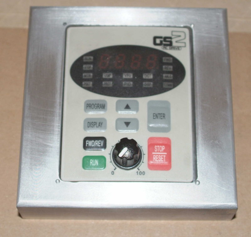
The panel is an easy fit, perhaps .10" clearance on each side. It will be held in place with a M4 screw through the back.

large.jpg


I'm not sure where I will mount the panel. I'll decide when the mill is re-assembled and I find an ergonomic spot.

When I got home and opened the box containing the remote cable, I found that I'll need to make the access hole about .25" wider to accomodate the molded plug.
 
Nice work Kvom. Those classes are paying off huge.

Steve
 
My electrician buddy looked at my proposed setup, and we came up with the following "final" configuration:

a) Large enclosure will mount to the wall over the current wall box. The 1PH wire will enter the enclosure via a hole to be cut in the back.

b) The wire will then exit the enclosure via a knockout and into a switchbox's knockout; the switchbox will be attached to the enclosure.

c) The switched 1PH wire will lead back through the knockouts and thence to the VFD.

d) The 3PH output will lead out from the enclosure via a knockout to a knockout on the smaller encloure.

e) Within the small enclosure the 3PH power leads will be connected to the motor leads via wire nuts (these being deemed the most secure connection

f) The small enclosure bolts to the motor.

Should be neat. If he gets the rest of the needed parts we might try to get it all wire up on Wednesday afternoon.
 
Very nice remote panel! That will be easy to mount when the time comes.

On your VFD enclosure, is there ventilation to get the heat out of the enclosure? You stated that you have clearance around the VFD, but if the air can't get in and out of the enclosure...
 
In theory (as per someone on PM who seems to know his stuff) there will be enough heat dissipation given the size of the metal enclosure. If this proves not to be true I can open out some of the knockouts.
 
With all due respect to everyone here or otherwise...

There's a problem with that theory. It is the lack of heat transfer that will occur. What is going to happen is the air in the enclosure will be heated by the VFD and will rise to the top of the enclosure. It will not be able to go any farther. The air will then start heating the enclosure, and this transfer of heat is poor at best. The enclosure will then have to vent its heat to the outside atmosphere, and this will take some time to happen. If there is air flow over the enclosure, then the transfer will be faster than it would be in stagnant air. It is still a slow and inefficient method to move heat.

Once your air volume in the enclosure gets heated up, there will be little if any convective flow through the drive, and the air will be unable to carry enough heat from the VFD to effectively keep it cool. In other words, your convective air flow will have effectively stopped, and any further cooling will then have to transfer through the heated air to the enclosure, and then away from the enclosure. As this take place, the air will become hotter and hotter.

It doesn't matter how much surface area your enclosure has to it, it is a matter of air flow and air temperature. The transfer of heat is faster when the temperature difference is high, but this process slows considerably as the temperatures come closer together. The surface area of the enclosure will surely be greater than than the surface area of the heat sinks in the drive, however the transfer of heat will be compromised in any sealed enclosure. The more volume the enclosure you have, the longer it will take to heat the air mass up, but the results will be the same.

If you look in your documents that came with the drive, I bet there is and operational temperature range included. I strongly suggest keeping the drive within the prescribed environment. Failure to do so will shorten it's life span considerably.

If you choose to leave the enclosure sealed, then watch the temperature inside carefully and make the determination if you have a workable environment for the drive. I am am pretty sure your temps will be higher than prescribed in the manual. And you might be surprised just how quick the air becomes heated! I'd hate to see you loose the drive over a minor detail!!

 
I will definitely monitor the temps.

The box itself has an overheat protection, but I son't want to rely on that of course.

One issue is whether the unit generates heat when the mill's motor is not running. I am assuming it does not. My experience with mills is that operation is very sporadic.

In addition to convection, the VFD's metal back is in contact with the back of the enclosure, so there is some heat dissipation by conduction as well.
 
Your are correct in the sporadic nature of running a mill, but there will be more heat generated as the load on the motor increases. When I am running my mill, I find that I run it sporadically, but it can be in operation for a few hours at a time (not constantly). With more frequent starts of the motor, there is heating generated by the inrush current of the motor and this will compound itself as things warm up.

You are like me in that you want to use the over heat protection as the last line of defense. That's a good plan, and things can go wrong!

As far as the back of the drive being against the enclosure, you are right in there being a decent heat transfer through that contact, but also keep in mind that the rear surface area of the drive isn't large enough to dissipate all of the heat. If it were, there would be no need for heat sinks and vents in the case.

Just keep an eye on it and be aware that you may have an issue sitting there.
 
kvom,
Just a suggestion. You might want to put some thermal conductive grease between the VFD heatsink and the enclosure bulkhead you bolt to. I'm talking about the stuff used between a CPU and the heatsink in a computer. This should help heat transfer to the enclosure tremendously. You won't need much, maybe about the size of a dime and half as thick. It'll squish out when you tighten it down. You should be able to pick some up at any electronics shop or a place that custom builds computers.

The grease effectively increases the contact area between the two surfaces by filling in the space between any bumps and ripples that normally wouldn't have any contact.
 
Good thought. I actually have a tube of that stuff (silver grease) that I use on the plug contacts for my trailer.
 
kvom,
Thanks for starting this thread.

ksouers,
Thanks for mentioning that grease! I had never heard of it. I will buy some soon. I am finishing installing two VFDs in a single enclosure. One a 1 HP, and the other a 3 HP and I am afraid that I will have a problem with heat.
Kvom,
 
I'm building a NEMA enclosure for CNC electronics and heat will be a concern there. 120V AC fans are really inexpensive and one in the top of the enclosure will draw off the heat very nicely.
 
I am thinking of adding a fan. But I will need to have a filtered opening on the other end for the air to enter. I already have the filters and holders. Need a fan. I contacted factorymation (sp?) and they told me that I should have 24 cfm air movement through there to be safe.
I got extra holders and filters through a trade, in case anybody is interested.
I apologize if I am highjacking the thread.

Fred
 
Here is the "mostly-finished" VFD hookup:

large.jpg


The power line enters the large enclosure via a hole in the back and leads up into the small switchbox. HD didn't have the 230V switch in stock, so that remains to be wired. From the switch the 3 conductors attach to the top of the GS2 VFD. The 4-conductor 3phase wire connects to the bottom of the VFD andf leads out to the small enclosure mounted on the mill's motor. There the 3 power leads are connected to the T1/2/3 leads of the motor, and the green ground lead is grounded to the enclosure and motor via the mounting screw.

The remote control cable is routed out the side knockout. I haven't decided where to mount the control panel, and will try various spots before attaching permanently. I think the most likely spot will be the DRO mounting arm between the DRO and the mill.
 
A large heatsink will take longer to heat up, but it will also take longer to cool off.
Top fuel drag racers will fill the cavities of their engines where the water usually would be. All is fine but as soon as that engine gets too hot there is a failsafe that automatically turns off the engine. Great for short drag races.
As War eagle said, you need a way to get that heat away from the heatsink. Fins will vastly increase the surface area allowing heat to be stripped away via air.


Atta boy!

Cant wait to see some oil sprayed over those brand new walls!

Im still building my medium sized shop and will get to your size one day.

My dad is a master wood turner and is thinking about downsizing to a smaller house with larger shop. we build woodturning tools to sell.

A setup like yours will be an easy sell,

Thanks for sharing.
 
Hello,

I agree with the idea of heat dissipation. My Hitachi phase converter unit on the mill comes with a fan to cool the components. It not only cools the components but discharges the capacitors when you tun it off. It is, however a bit noisy, but with the variable speed, and phase generation, it is a price I am willing to pay for the convenience.

Best Wishes

Chuck M
 
The mill has been under power for a while and has had a few test runs. VFD has a small circulating fan itself. I mounted the remote panel to the DRO arm with a machinist's clamp, and that seems a good spot. I will try to make a permanent bracket one of these days.

Biggest problem I've seen so far is that running on the high-speed pulley I lose too much HP at lower spindle speeds. 60Hz=2750 RPM, so at 1000 RPM i've lost 2/3 of my 1HP motor. I think I will probably settle on one of the lower ratio pulleys, and if I need higher speed I will overspeedf the motor.

It was suggested on another forum to replace the motor with a 2HP, so I guess that's an eventual option.

I had to replace the spindle brake handle. While I don't need it to place/remove collets or to stop the spindle, I do need it to lock the spindle when tramming.
 

Latest posts

Back
Top