Help! Brian Rupnow's Hit & Miss Steam Engine Build

Home Model Engine Machinist Forum

Help Support Home Model Engine Machinist Forum:

This site may earn a commission from merchant affiliate links, including eBay, Amazon, and others.

deadin

Well-Known Member
Joined
Jun 29, 2009
Messages
102
Reaction score
4
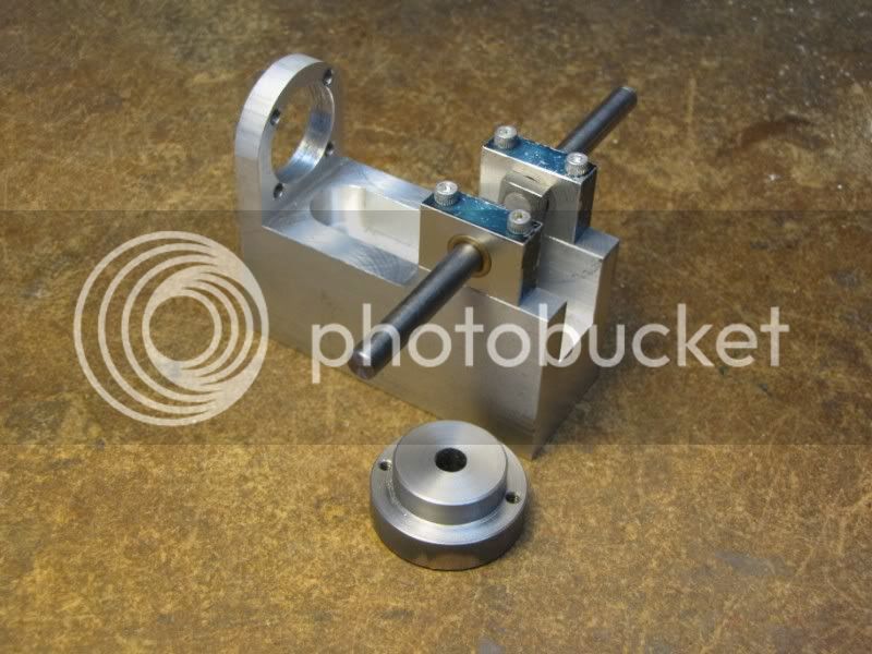
OK! I'm trying mt best to follow Brian's plans and pictures of the build described here:
http://www.homemodelenginemachinist.com/index.php?topic=5234.0

I've been doing pretty well (the plans are great!!) however, there seems to be an epiphany between reply #13 and reply #14 of the above. ;D
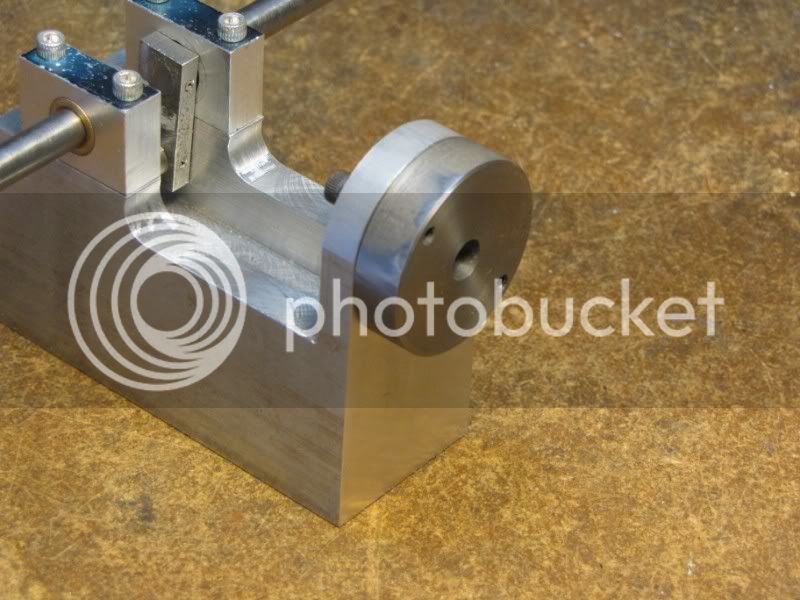
I understand the boring of the hole in the crankcase for the cylinder, but I can't for the life of me figure out how to create the .625 radius that suddenly appears in reply #14. (around the upper half of the cylinder hole.)
Surely it's not done freehand with a file. ;)

Also, are there any specs for the slider valve in the cylinder head? (Or did I miss something in the plans?)

Thanks,

Dean (And I just discovered what was meant by "If your rich, you can use brass" :hDe:
 
Dean,
You can use filing buttons for this task. Turn up two disks of 1.25" dia. with a short length to fit in the bore of the crank case sort of like a cylinder head of a steam engine. Drill a clearance hole in the center of each and bolt them sandwiching the crank case between them. Using the buttons as guides file down to size.
For more info on "filing buttons" enter those words into the search window on the home page. When I tried it I got several hits including
http://www.homemodelenginemachinist.com/index.php?topic=4294.0
see reply #6
Hope this helps.
Dave
 
You can also do it incrementally... Repeated cuts with an endmill just tangent to the outline will create the contour with a slightly scalloped finish. Then a file or belt sander will finish to the desired shape.

There's a program on my website that will do all the necessary calculation. Look for the ROUNDER archive.
 
I ask Brian about the piston in the head, he said crs .250 X .375 I used 12L14 and a light spring to preload. I just cut the crankcase on the belt sander and finished it up with a polishing cloth.
Hope this helps.
 
Speaking of filing buttons...

I'm building this engine too. Normally I would use my ROUNDER program to profile the base but since the cylinder head needs a similar profiling, I elected to go the filing button route.

The first photo shows the button. It has a 0.9" diameter section to fit into the base hole that will accept the cylinder and has two 5-40 tapped holes so it can be secured.

FBUTTON1.jpg


This photo shows it in place on the base

FBUTTON2.jpg


The central 1/4" hole in the button was used as a pivot to remove most of the stock using my rounding over fixture (covered in an early post). Then a vertical 1" belt sander was used to get the final contour. When the sanding belt sparks off the steel button, it's time to stop sanding.

The cylinder head has four 5-40 clearance holes used to attach it to the cylinder. Instead of drilling those I'll tap two of them 5-40. Then I'll drill out the 5-40 holes in the button, bolt it to the cylinder head and use it to do the profiling on the head. Once the head is profiled, I'll drill out the 5-40 tapped holes to clearance size.

Being parsimonious, I'll then throw the filing button in my lathe fixturing thing-a-ma-jig box. It's surprising how frequently yesterday's fixture can be cannibalized to make something for the current project.
 
When I build the original engine, I used a metal cutting band saw to cut off the two corners at 45 degrees, then used a stationary belt grinder to finish of the the radius.

Chuck
 
Back
Top