Governor Weight/Spring Combinations On My Upshur Hit-and-Miss

Home Model Engine Machinist Forum

Help Support Home Model Engine Machinist Forum:

This site may earn a commission from merchant affiliate links, including eBay, Amazon, and others.

rudydubya

Well-Known Member
Joined
Nov 26, 2008
Messages
337
Reaction score
7
Hi folks. Thought you might be interested in seeing how my Upshur hit-and-miss runs with different governor weights and springs. Nothing much new here. I just wanted to look at light weights and heavy weights, weak springs and strong springs, and see how different combinations affected how my engine runs.

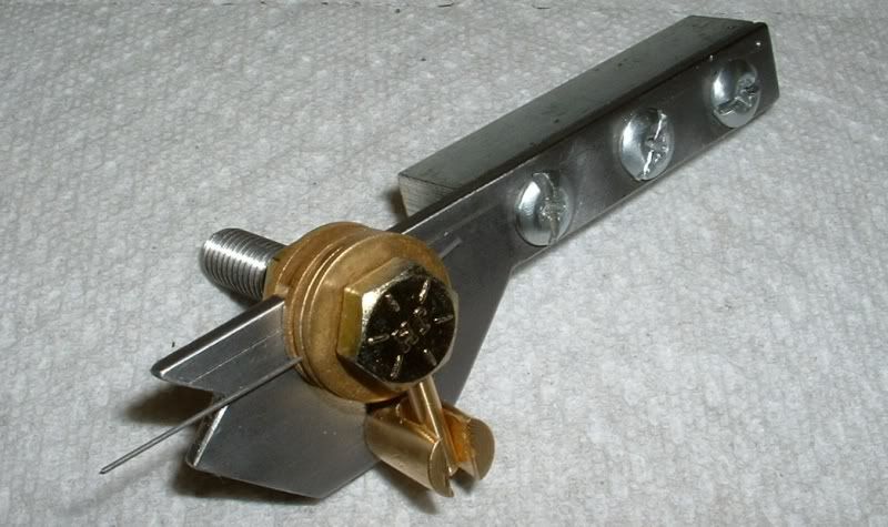
Here's a picture of the weights and springs I'll be trying. I've used the bottom set of light weights and the top set of weak springs (as shown at the right) since I built the engine a couple of years ago, so I'm calling that combination my "standard" configuration. The standard weights are half as long, and half the weight, as the longer, heavier weights shown at the top. The standard springs are much weaker than the stronger springs shown at the bottom (the stronger springs have a spring constant about 5 times that of my standard springs).

GovernorWeightsSprings.jpg

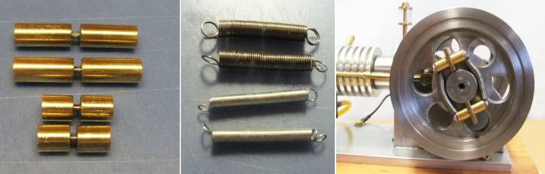
Here's the video. It starts off with my standard configuration: light weights and weak springs. Then I change the weight/spring combination for each next run. It's self explanatory. Not a professional narration. I tried to fire the guy, but he has tenure.


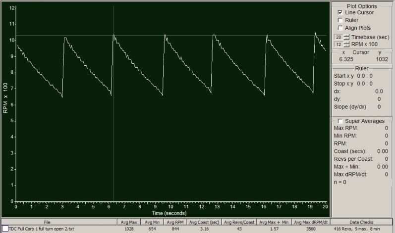
The stronger springs clearly made the engine run faster, and the engine slowed to a stall with the heavy weights and single weak spring. Between those extremes the engine ran pretty good no matter what combination of springs and weights it had. Maybe if I wanted to tune it for power I'd look at some combination with stronger springs. Or if I wanted a slower runner I might consider heavier weights or even weaker springs.

Hope you enjoyed it.

Regards,
Rudy
 
Hi Rudy, say, thanks for sharing. It was good to see a visual side by side comparison of the different weight/spring combinations in real time. Nicely presented. BTW, that is a nice little runner you have there.

BC1
Jim
 
Thank you Jim. Much appreciated.

Regards,
Rudy
 
Rudy - Very nice video and engine. It really runs well. Did you make your own springs? If so would you mind sharing your technique?

Thanks for sharing your research.

Harold
 
Rudy,
Very nice presentation.
I can appreciate it all that much more as I just adjusted several identical H-N-M engines to run at the same, more or less, RPM for an in progress project.
Gail in NM
 
Harold and Gail, thanks.

Harold, I made the weak springs like Dean shows in his excellent tutorial, but I used a different tool and didn't know enough about springs to heat treat them. My tool was made from plans I found in the March - April 2007 issue of Model Engine Builder magazine. I also used it to make my valve springs. It has a notched end that butts up against the mandrel to keep it from bending while the spring is being wound. I didn't make the strong springs I used in the video, I got them out of my junk box and cut them to length, I think I originally found them at the local hardware store.

SpringTool.jpg

Regards,
Rudy
 
GailInNM said:
... I just adjusted several identical H-N-M engines to run at the same, more or less, RPM for an in progress project.
Gail in NM
Dang, Gail, have I missed one of your projects?

How are you measuring the RPM of your engines? I struggled with that for a while for my simple hit and miss, became obsessed with it, and finally did it this way. No engine analyzer, and not real-time, but it does what I wanted. My solution: Buffer and sample the output of the Hall sensor with a cheap PC USB data logger. Save same in a readable format. Put together some basic software to analyze the readable file, calculate time between sensor pulses, and convert to RPM. Plot same. Add bells and whistles. Putting it together was almost as much fun as playing with it (and talking about it). Here's a typical plot, twenty seconds worth of one run saved while I was trying to get the needle valve set right. RPM versus time.

TypicalRun.jpg

Regards,
Rudy

 
Hey Rudy, I'm getting close to making the springs for my Upshur. Timely post on your part. Thanks for the info.

BTW, Harbor Freight sells a box of springs for pretty cheap, all sizes and types. There's one in there that is a good fit for the exhaust valve but I'll have to make or modify something for the intake as the ones in the box are too stiff. Looks like I'll be making the springs for the weights as well.

-Trout
 
Hi Rudy,
Not being trained as an engineer I don't have the background but I recall reading somewhere in the past that centrifugal force is a constant and affects objects of differing weight the same. That being said what you are probably finding is that by changing the springs is having more affect on the running speed than the change in the weights.
Someone with the correct knowledge can weigh in here at any time.
gbritnell
 
The equation for the centripetal force is:

F = m * w^2 * r

where

m = mass (not weight) of object
w = angular speed (rad/sec)
r = distance from center of rotation

You can see from this equation that, if w and r are held constant, the force will change with changing mass.
 
Rudy,
Unless you missed my "Tiny" H-N-M locomotive at the tail end of Arv's (Putputman) Tiny engine thread then you have not missed anything. The locomotive is shown a few posts in at:

http://www.homemodelenginemachinist.com/index.php?topic=8096.330

with some additional video on the following page.
This was a proof of concept version. The current project is a continuation of that with the locomotive dressed up a bit to look more like the prototype which was a 1896 Woolwich Armory industrial locomotive. I have not posted anything on it yet. Unfortunately, while showing the original at a steamup in Utah with a group of friends there were a few "I gotta have me one of those." comments, so I am building several. The engines are done and I am working on the chassis now.

Here is a link to the tachometer that I used to set the RPM.
http://www.homemodelenginemachinist.com/index.php?topic=15728.0

I worked fine for what I was doing because my engines are running a a much higher RPM than yours. I set the governed speed at 3000 RPM with a fairly narrow range between the high and low RPM through the H-N-M cycle. With a resolution of 60 RPM this is about 2 percent and that is fine for what I wanted. At your RPM engine I suspect that it would not be of much use.

I want to build up an analog meter tachometer using a PIC processor at some time so I can have a real time needle to watch when making adjustments. One thing I would like to do is to put a clip on electret microphone on the exhaust pipe to count and display the number of Hits that the engine is making. Heat shield coupling to avoid heating the microphone element. With a PIC I could also the RPM by this number and display the revolutions between hits. But, I don't need it now so I don't know if or when I will build it. And when I will need it I will be nearing the end of an engine build and not want to stop the progress on that to build it. Kind of like the old "I don't need to fix the roof now because it's not raining so the roof is not leaking" syndrome.

There are so many things that can change H-N-M performance depending on what you want. On my last display engine where I waned a greater spread between high and low RPM, I introduced additional hysteresis in the linkage by making the groove in the spool wider than the following pawl so the exhaust w0ould lock out and then the engine would have to slow more to pull the lockout latch away to permit a Hit function. Of course this only works if there are no springs in the system beyond the spool. Other things that can be done is to change the operating angle of the weight arms to alter the positions of the weights when lockout occurs. You can change the effective spring rate that way (sine/cosine functions) much like a snap action switch, but this just about has to be done during the design and does not lend it's self very well to changing after an engine is built.

Gail in NM


Thanks Marv,
I thought that someone more versed than myself would help out.
George
 
Trout, thanks for your interest. Looking forward to reports of your progress. I don't think I mentioned it, but my "weak" governor springs were made from 0.015 music wire, about 56 turns close-wound, 0.185 final O.D.

George, thanks also. I've admired your work ever since I got into the hobby. I'll never get to your level, but your work inspires me to try.

Marv, thanks for the refresher, I forgot most of my college physics long ago, only vestiges left.

Gail, I followed your (and Arv's) "Tiny" build with interest. Nice to see one put to work. I'll be looking forward to your progress on the follow-on. I considered using a microphone near the exhaust, and even some sort of microswitch on a flapper valve on the pipe, but never pursued either idea. I can see when the engine fires now from the RPM plots. And thanks for the tips on the governor design.

Regards,
Rudy
 
A final couple of pictures to finish off this topic and better illustrate the differences between runs in the video.

What you see in this first picture is a four-second display of RPM versus time, comparing light weights and heavy weights, with the weak springs used in both cases. The yellow plot shows the heavy weights, and the white plot the light weights. If you look closely, you'll see little "x" tick marks on the plots. Each tick mark is a revolution of the flywheels. The engine hit-and-miss cycles are also clearly shown. For example, the yellow plot starts off with a low-RPM "hit" near the beginning at the left and increases rapidly to a peak at about 950 RPM. Then, a gradual slowdown while the engine coasts, to around 575 RPM about 3 seconds later, at which time the engine hits again. It then reaches another peak at 950 RPM in only a couple of flywheel revolutions, then starts to coast again.

LightWeightsvsHeavyWeightsWeakSprings.jpg

From the picture it's clear that with the heavy weights (plotted in yellow), the engine runs slower overall with a shorter coast time than with the lighter weights (plotted in white).

The next picture is a plot comparing weak springs and heavy springs, with the heavy weights in both cases. The strong springs (yellow plot) clearly speed up engine operation and shorten coast time. Note that the RPM scale is expanded to show the higher RPMs.

LightSpringsvsStrongSpringsHeavyWeights.jpg

A couple of additional notes about the plots. The jagged nature of the higher RPM plot is a consequence of my sampling rate in getting the raw data. I sampled the Hall sensor output every 1.0 millisecond for all the runs, so the data logger could have missed the start of a sensor pulse by as much as a millisecond. At around 1400 RPM, one millisecond could mean an error of about 30 RPM between points. At lower speeds the effective error is much less, hence the smoother plots. The numbers at the bottom of the plots are averages for each case, taken from a run much longer than the four seconds shown. The block colors next to the file names correspond to the plot colors. My plot software selected the start points of the plots so they would be easier to compare.

Regards,
Rudy
 
Further to Marv's post, the force required to expand or compress a spring is given by Hooke's law:

F = kX

where k is the "spring constant" and X is the displacement. If we make simplifying assumptions then we can say that

kr = m * w^2 * r

which yields

w^2 = k/m

Not surprisingly, this shows that a larger mass gives a smaller speed and a stronger spring gives a higher to trip.
 

Latest posts

Back
Top