Getting the most from your Dremel

Home Model Engine Machinist Forum

Help Support Home Model Engine Machinist Forum:

This site may earn a commission from merchant affiliate links, including eBay, Amazon, and others.
Dave,

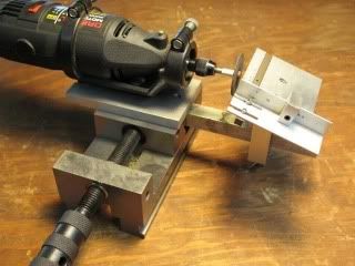
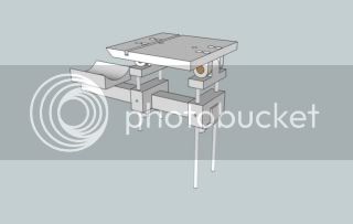
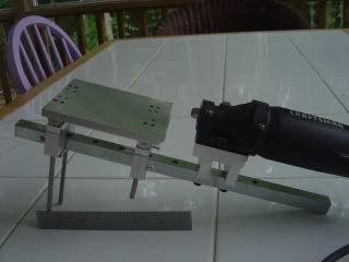
There's nothing sacred in the design - no critical dimensions or materials. The design of the Dremel mount will depend on what sort of (Dremel) fixture you buy and the materials you have to hand.

After you have the tool mounted and have a "backbone" in place use your creativity in designing whatever sort of ancillary fixtures you need for the type of work you anticipate. After you have the basic structure in place, ideas for further attachments will occur to you as you use it.
 
Someone asked me for more details on the construction of this device so...

DREMEL-1.jpg


This pic shows the box that contained the Dremel router jig that donated the plastic holder that secures the Dremel motor tool to my attachment.

DREMEL-2.jpg


Here you can see the head of the carriage bolt that secured the plastic holder to the router jig.

DREMEL-3.jpg


The carriage bolt has been extended through the aluminum baseplate and "backbone" rail and secured with a nut. The backbone is further secured to the base plate with two socket head cap screws.

DREMEL-4.jpg


This view shows how the tilting accessory table is secured to the backbone. A removable spacer under the table clamp allows for two table heights because, when the table is tilted, the working end may be too high for the tool in the Dremel chuck and the table must be dropped. (There's clearly room for improvement in this aspect of the design.)

DREMEL-5.jpg


An alternate way to attach the Dremel is to remove the threaded plastic ring at the end of the tool. This reveals a section of 3/4-12 thread which allows one to make accessories such as the aluminum one shown into which the Dremel will thread securely. Think of a slab of aluminum so threaded and held in the QCTP to allow the Dremel to be used as a (desperation) tool post grinder.

DREMEL-6.jpg


Recently Dremel introduced the all-attitude tool holder shown here. It's a useful bit of kit in its own right but look closely and you'll see that the plastic tool holder is identical to the one I liberated from the router jig. If you can't find the router jig or you find this holder more useful, I'm certain you could use it to make my device.
 
That ancient TI scientific calculator you've got there still works huh? :big: I think that takes me back to my college days....
 
Troutsqueezer said:
That ancient TI scientific calculator you've got there still works huh? :big: I think that takes me back to my college days....

No (spit) TI. That's a pure solar (no battery) Casio that I've had forever. It just keeps on ticking.

When I went to college, my calculator was a slide rule. Still have it. I plan to use it to teach my grandchildren about logarithms.
 
Thm:
Thanks Marv
now I will put my dremal to work

Dave
 
This is the mild steel adaptor I have made that enables the Dremel to be mounted in a tool holder. It fits inside the two ridges on the bottom of the Dremel holder and is secured by an M5 screw. The underside of the adapter has 3 M5 holes for fixing the various attachments, yet to be made :-[

John


DSCN3258.JPG


DSCN3259.JPG


DSCN3260.JPG
 
Marv,

After looking at this:

mklotz said:
DREMEL-5.jpg

An alternate way to attach the Dremel is to remove the threaded plastic ring at the end of the tool. This reveals a section of 3/4-12 thread which allows one to make accessories such as the aluminum one shown into which the Dremel will thread securely. Think of a slab of aluminum so threaded and held in the QCTP to allow the Dremel to be used as a (desperation) tool post grinder.

I got to thinking about comments over the years about runout while using Dremel tools. In a lot of cases, they were held by a threaded bushing like this. It seems to me that with that relatively huge weight out the back spinning at thousands of RPM a good deal of the runout could come from shake in the back end. That could imply that your use of the router bracket could be reducing this effect a lot.

In the early days, things were simpler with the Dremel. I still remember my first one: straight cylindrical body with a transition to a cylindrical nose. That one would have been easy to make a bracket to hold in multiple places.

Alan
 
Alan Haisley said:
In the early days, things were simpler with the Dremel. I still remember my first one: straight cylindrical body with a transition to a cylindrical nose. That one would have been easy to make a bracket to hold in multiple places.

Perhaps it's just my German cynicism but I think that Dremel alters their case design every year or two just so you're forced to buy new versions of their accessories.

One of the most satisfying aspects of having the skills and tools to fabricate "stuff" is being able to defeat such devious marketing tactics.
 
When I went to college, my calculator was a slide rule. Still have it. I plan to use it to teach my grandchildren about logarithms.
Now THAT will teach them a lesson :)
 
mklotz said:
No (spit) TI. That's a pure solar (no battery) Casio that I've had forever. It just keeps on ticking.

When I went to college, my calculator was a slide rule. Still have it. I plan to use it to teach my grandchildren about logarithms.

Hi Marv

Casio fx-115M ??

Mine's still ticking too. I believe I bought it in 1992 .. or 1993

BC
 
Brilliant Marv. I use the abrasive cutoff wheels on my Dremel a lot. This set up would solve a lot of problems. Thanks for doing this.

vr Bob
 
Marv,

Thanks for the
dremel2-11.jpg

inspiration.

Using Google Sketchup, I drew up an initial plan
DremelFixture.jpg


The realization in metal was slightly modified
DSC00037.jpg

I hadn't allowed for just how much the table tilting hinges would raise the lowest level of the table and so had to make a couple of blocks to raise the tool center after the fact.

The backbone is a piece of 1/2"x1/2" plated keystock. In it, I drilled holes on 1 inch centers to pass 10-32 screws. By drilling pretty much the whole length of the bar, it will allow me to move the mototool back and forth if desired.

The second picture should give a good idea of how the hinges and risers were done. The hinges were the only major challenge since they are rounded over. I first made them as squared-off blocks. After drilling the pivot holes, I made a mandrel that let me hold the pieces horizontally with a chuck attached to my rotary table. The other end was supported with a center point. I then milled and turned, milled and turned, milled ...

Eventually things were rounded off to my liking. I then drilled and tapped holes in the upper pins for 2-56 screws. The bottom parts of the hinges were drilled to hold the elevator rods, which were then superglued in place.

All that is left to do with this basic unit is to replace the screws with brass thumbscrews to protect the elevator rods.

The elevator rods are O-1 drill rod, the hinge pivots are brass, the bottom clamp plates are CRS. All else is Aluminum.

Alan
 
Well done, Alan. I'm always pleased and flattered when someone thinks enough of my ideas to build one for himself. I think you'll enjoy the tool and building accessories for it to extend its range of use.

For those rounding over tasks, you may find the technique described in my ROUNDER program text file will get the job done quicker and not require dragging out the rotary table.
 
Marv,

That's an awesome fixture for the Dremel!

You ought to market it- I bet a lot of people would buy it (or well the idea to Dremel!)

Best,

Nelson
***************.com
 
Back
Top