Gear tooth template

Home Model Engine Machinist Forum

Help Support Home Model Engine Machinist Forum:

This site may earn a commission from merchant affiliate links, including eBay, Amazon, and others.

Kactiguy

Well-Known Member
Joined
Nov 11, 2007
Messages
86
Reaction score
1
Birk asked me to post this drawing he did explaining how to draw a gear template for shaping your tool bit. He says it works great and I have to believe him. Hopefully it will all show up in the scan. If I need to I can put in the download area.
geartemplate.jpg

 
I had Guy post these instructions, because for some reason it does mot work for me. Remember the drawing for the chime whistle came out all blurry?
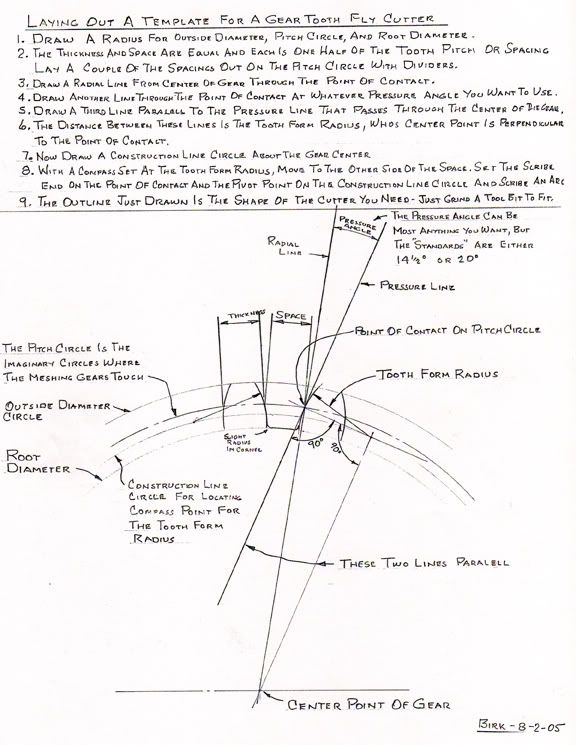
I have been using this method of developing gear cutters for quite a number of years. A while ago a couple friends inquired how it was done so I made up the instruction sheet. The radius curve developed is very close to an involute curve for the short distance it travels. When making the layout I use good quality drafting instruments, with hard sharp leads, and a needle sharp point on the compass. Most always I make the layout double scale because it is easier to draw it larger. Then I make half size copy on the copy machine to work from. That also cuts any error made in layout in half. Just the width if a line can make a difference. The grinding of the cutter bits is a trial and error operation. That is grind a little bit and lay it on the outline to see where more needs to be ground off. Grind an check, grind and check. When you grind it all away, grab another tool bit blank and start over. Hopefully that will not happen though.
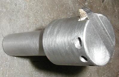
While we are on the subject, If you make your own single tooth holder (fly cutter) machine one side of the slot that holds the tool bit on a radial centerline. If you center the slot on the centerline, then the leading edge of the bit will have a negative rake, and negative rakes do not cut as well.

PA250001.jpg


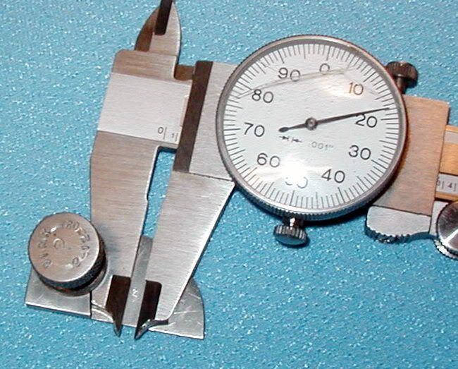
It is a good idea to check the tooth thickness at the pitch line. It it is too thin the gears just rattle a little, but if they are too thick they will not mesh. To do this I made an attachment to fit on my calipers, that is set to the addendem, with help of the depth rod of another caliper. So many of the gears that I work with are so small I had to grind the caliper points to fit down in between the teeth. Calipers are so inexpensive that I just dedicated one to being a gear gage.

P2050001.jpg


As with all problems there is usually more than one solution. In his books on building geared model logging locomotives, Kozo Hiraoka describes some unique ways of making gear cutters. Smart Flix rents a video showing how to make and use a gear cutting hob that looks kind of fun. Then as a last resort, you might consider using commercial gear cutters. Of course that takes the challenge out of it.
Birk
 
Hi Birk.

I dont know if this will be of interest but I found it some time ago whilst searching for a source of made gear cutters (since found). I have used the method described to make a couple of odd gear cutters for one off jobs 18DP if memory serves a size I cut very seldom).

http://www.metalwebnews.com/howto/gear/gear1.html

The description is good and as long as the cutters are well hardened and tempered they work as well as comercial cutters. I must admit the most fidely part was making the buttons and getting two tempered the same. In the end I stacked them on a cast iron pin and heated both at the same time. A better way would have been in a sandbox for hardening and a plate for tempering.

Cheers kevin

 
Kevin
I have often had thoughts of working up something to make gear cutters similar to what you have just shown, But I never get around to doing it. It seems I'm always in too much of a hurry, so I just grind another bit the way I have always been doing it. I really need to slow down and think it over for a while. Thanks so much for your input. I'll do some more considering.
Birk
 
Hi Birk
I must admit that the fly cutter is a quick way to set up for gears.
I have jobs that have been on the plan to do list for 15 years il get round to them one day.

Most of the gears I cut are in cast iron and to very close scale. One thing I have found is that cutting gears with a full cutter allows each tooth to be cut in one go even on somthing like 10 DP. The trick is to cut a tooth and skip a few teeth. Doing this lets the gear wheel cool down after the large cut. I mostly do this to ensure uniform depth on all the teeth but also to reduce wear and tear on the cutters. Most of mine are 10 plus years old and only one has wanted sharpening in that time.

One thing a lot of people dont consider when making gears for traction engines is the sound. Steel gears are very popular and a bit cheaper than cast iron but they sound wrong. Steel is a dull sound as it meshes cast iron rings and sounds more like the full size engine.

All said and done with the results your getting I doubt you have that much to gain from changing what you do. Your helical gears look superb.

Just as a passing story about gears. A good few years ago an associate of my brothers re toothed one of the pinions in the compensating gear from his Marshal traction engine (full size). After many weeks of work he decided to normalise the gear pinion in the firebox of a pumping station boiler. His plan was to soak the gear for a few hours as the boilers came up. With out knowing it his mate opened the damper on the frebox and burnt all the teeth back off. Gears you gotta love em.

Cheers Kevin
 

Latest posts

Back
Top