Fun with Worm-Gear drives

Home Model Engine Machinist Forum

Help Support Home Model Engine Machinist Forum:

This site may earn a commission from merchant affiliate links, including eBay, Amazon, and others.

Brian Rupnow

Design Engineer
Project of the Month Winner
Joined
May 23, 2008
Messages
15,001
Reaction score
8,299
Location
Barrie, Ontario, Canada
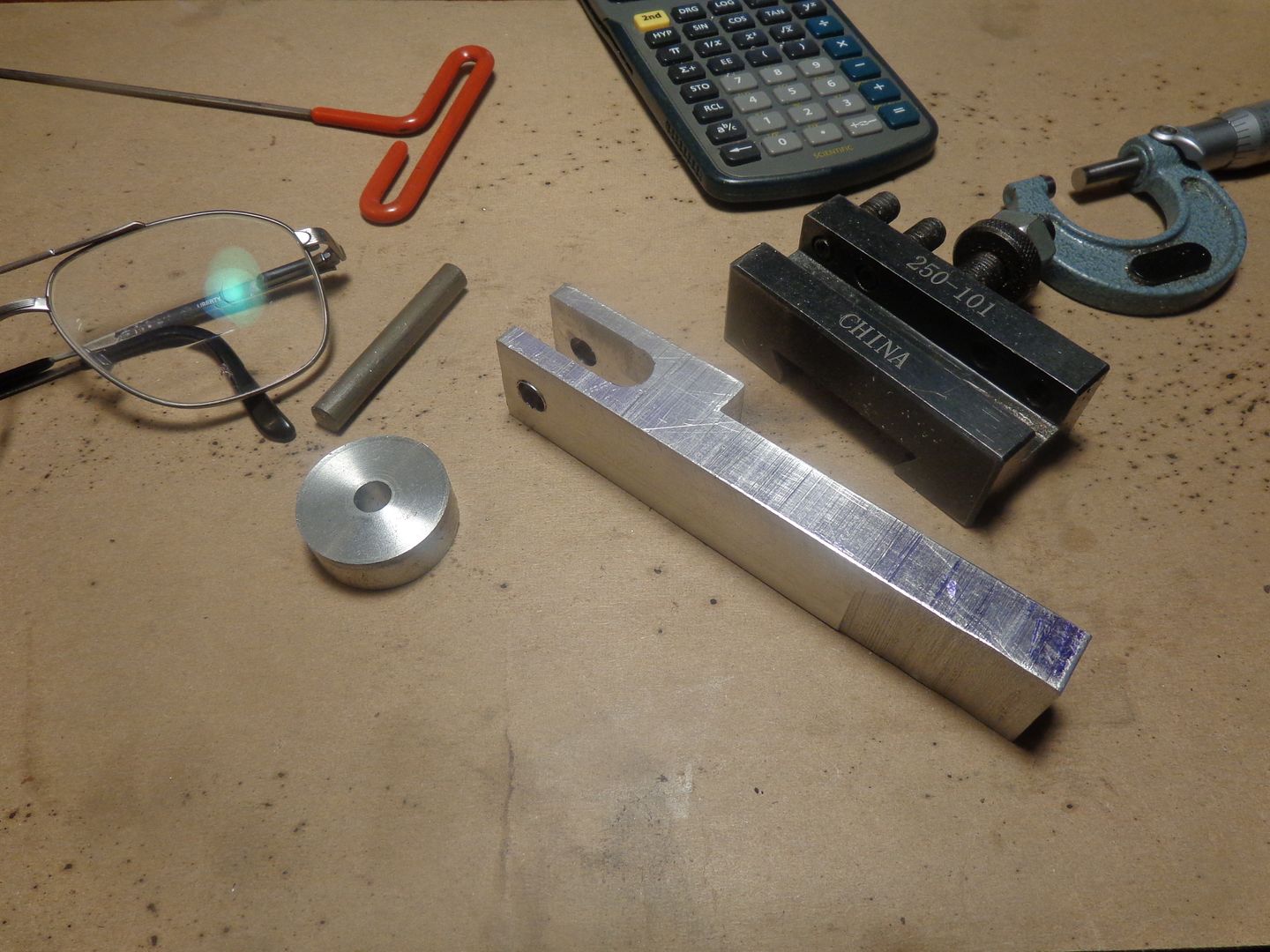
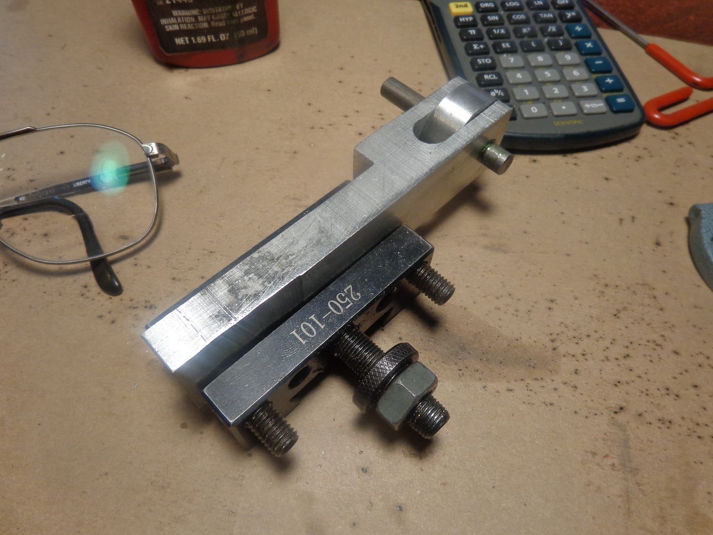
A couple of months ago, I seen on one of the forums I visit that someone had cut a worm gear by mounting a tap in the chuck of a lathe and letting an aluminum blank rotate against the rotating tap. The tap caused the blank to revolve, and with some pressure from the cross feed on the lathe actually cut "teeth" into the blank. There is still 20" of snow outside (although it is melting ) so I decided to play inside today and try this for myself. First I turned a blank to an arbitrary 1.25" outer diameter x 7/16" thick. Then I made a holder to mount it in with a piece of 5/16" cold rolled steel for an "axle", and this in turn was mounted into one of the tool=holders for my AXA toolpost.

 
I then mounted a 3/8"-16 tap in the chuck of my lathe, set the lathe on its lowest speed, and centered (well, I thought I had centered) the blank on the centerline of the tap, and then began to turn the crossfeed handle until the blank touched the rotating tap and began to rotate with it. I would feed about .010", then let it rotate for a couple of minutes, then feed in another 0.010". I didn't know what my limiting factors would be, and I didn't want to break the tap, so when I thought that the newly cut "gashes" (can't really call them teeth) were deep enough I stopped..

 
As you can see in this picture, the blank wasn't centered as well as I thought it was in relation to the tap, but since this was only a "Try it and see" exercise, I wasn't terribly upset by the fact.

 
I then turned one end of a piece of 3/8"-16 threaded rod down to 1/4" diameter and made up a small bearing block for the 1/4" diameter to ride in, and mounted a pulley on the other end of the threaded rod. Through good luck and multiple measurements, the 3/8" threaded rod now meshed with the "gashes" cut into the side of the blank.

 
I set this all up in my mill vice, and put a stub arbor with a small pulley on it in the mill chuck, and connected the two pulleys with a 1/8" rubber o-ring drive belt. Since it is difficult to see a plain piece of aluminum rotating, I had made a number of marks around the side of the "worm wheel" so that it is more visible when it is rotating. It works!!! In fact, it works very well. I don't think I would want to drive anything important with it, but it does work, and would probably be fine for something "model size" that required this type of mechanism. Check out the video.---Brian
 
This is the same video, on Youtube.
[ame]https://www.youtube.com/watch?v=JZYwmKU70gA&feature=youtu.be[/ame]
 
Hi Brian - glad the snow is melting - think I'll have to cut the lawn this weekend ;)

You've described how I made the worm drive reduction for the oil pump on my Gnome. We'll see how it goes for longevity but it was an easy way to do what looked like a difficult thing at first.

Charlie

OilPump.jpg
 
Very cool Brian and Charlie. It would be an easy way to make a nice speed reducer.

Cheers,
Phil
 
Brian, were you able to accurately predict the number of teeth? I made a 72 tooth wheel using that general technique, but took a few tries to get exactly what I wanted, both in shape/depth and number of teeth. Needed a lot of "Kentucky Windage" to get the correct number of teeth.

Bill
 
No, I didn't even try. I just started with a 1.25" dia. blank and let the spacing of the gashes work itself out.
 

Latest posts

Back
Top