Fluted Columns

Home Model Engine Machinist Forum

Help Support Home Model Engine Machinist Forum:

This site may earn a commission from merchant affiliate links, including eBay, Amazon, and others.

Julian

Well-Known Member
Joined
Oct 24, 2007
Messages
164
Reaction score
0
Hi Guys

The table I have designed and built is configured as a dividing head to cut gears on my mill. Below is a photo taken during production and is not complete but the general idea is there. It still needs spraying and writing up for the magazine but IT WORKS!!!!!!!

http://i232.photobucket.com/albums/ee35/barneydog7/DSCF1149.jpg

Next link is the first gear cut on it. This was cut using a 24DP cutter on an arbor on the mill. I have since bought two 16dp cutters so the teeth are more in keeping with the engine I am presently building.

http://i232.photobucket.com/albums/ee35/barneydog7/PICT0100.jpg


Next are three pics of the work so far on the wheels for the traction engine. Rear wheel is just over 300mm dia and 50mm wide. Front wheel is about175mm dia by about 30mm wide. Also a pic of the front wheels on their steel axle with the almost completed perch bracket. I do not want to paint this engine. All non-ferrous parts will be buffed as they are. All steel parts will be nickel plated to keep them metal coloured but rust-free. This plating will be done with the Caswell Plating 'Plug n Plate' kit which should be here tomorrow. All these wheels are rolled steel and welded. The spokes are the same steel and the hubs are turned Ali. I intend to use as much ali as poss on this engine to keep the weight down. I have already acquired a 6" by 30" ali tube for the boiler. Whole engine should be about 40" long by about 18" wide and about 15" to the top of the cylinder block ( rough estimates at present)

http://i232.photobucket.com/albums/ee35/barneydog7/PICT0090.jpg

http://i232.photobucket.com/albums/ee35/barneydog7/PICT0092.jpg

http://i232.photobucket.com/albums/ee35/barneydog7/PICT0094.jpg


I did put the pics on as images but they were huge when displayed. Reduced on photobucket to thumbnails but still large. How do you make them smaller to show on the threads?


Julian
 
I recently bought a Grizzly X3 Mill/Drill (G0463) and it seems as if their R8 spindle is machined on the low end of specs so that some R8 tools won't fit in the spindle. I had a cheap set of R8 collets that fit my minimill but not this new mill. After a little research I discovered the ER collet system and bought an ER-32 collet chuck with an R8 taper. Lucky for me it fit the spindle. Now with a set of about 18 collets I can accomodate all tools between 1/32" - 3/4". That's a bonus for me because I often use wire drills in the 1/8" - 1/4" range. Four ER-32 collets cover that range for about $10 each.

Cheers,
Phil
Lancaster, PA
 
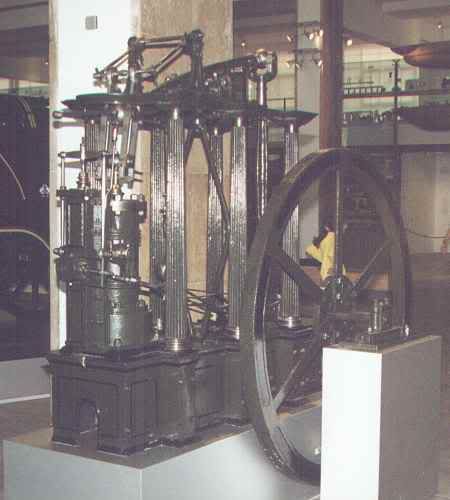
How does one go about getting a clean start and stop when cutting flutes in a column. I ground a tool bit with a rounded tip for the size I want and can place it side ways in the tool holder but don't know a good way to start and stop the flute so both ends look the same. These are the columns I would like to match.

flutedcolumnengine.jpg


Thanks, Kenny
 
Kenny,
Are you talking about doing it in the lathe?

To do it conventionally, it might look ok if you just gouge out the flutes with a scraping action (like when cutting a keyway) using the saddle movement to get them all near enough by eye, then just put a shallow relief cut around the column to remove all the missmatched end lengths (your depth of cut on the flutes is most probably only going to be about 0.005" to 0.010"), or put a small relief in first and run your cutter into it, or a very thin sleeve to slide over the column so the flute ends are covered up.
That is if your are making the columns straight, unlike the ones in the pic that are tapered, in which case you need to kick over your tailstock, and turning between centres, turn all your tapered columns, then put the tailstock back to centre and scrape away as before. This will give you a tapered groove that will match in with the taper on the column. You would need to be able to index your chuck fairly accurately to give a good looking column.
This is really the realm of the rotary table on the miller. Turn the columns to a taper of say 1deg, then set up your RT, mounted vertically, and EXACTLY square to the table. Then it is just a matter of using a small ball mill or engraving bit, coming from the top EXACTLY on centreline, and use the handle dials to give you matching lengths. Or setting the RT truly square as above and using a flycutter from the side EXACTLY on centreline, with a profile of whatever you want the flutes to look like. If using a flycutter you would have to give a length allowance to allow the cutter to miss the RT chuck.
In this case to get four good columns I would make about eight to give me something to play with to get them looking just how I wanted.
All this explanation, and all you have to do is make the fluted bits overlength. Cut them to the correct length and do as I did with my spiral columns, make separate end pieces for top and bottom.
You will find a lot of work like this is trial and error and you might find you need to kick things over at an angle to get everything to match up. Straight columns would be a lot easier.
Hope this hasn't confused you too much.
It has me!

John
 
HI Kenny

You cut flutes the same way you would on a conrod for a loco. Use a milling cutter rather than a ball nose end mill. just set the headstock on your will over or use a horizontal mill if you have access. Ball nose cutters leave a lot of cleaning up to do. you could do it using the cutter in the lathe chuck on a mandrel and the cross slide but set up would take a good amount of time.

Cheers kevin
 
If the columns are tapered, the flutes will need to be tapered too (normal practice is for both the flutes and ridges to taper so the ratio of flute width to ridge width is constant).

You can achieve this effect using a mill by setting up the column so the flutes are cut deeper at the base than at the top of the column and using a profiled tool.

The tool profile would need to such that the cut width increases linearly with depth (i.e. a conical cutter, but with a round nose) so that when moving from the top to the bottom of the column, the increase in width of cut is proportional to the increase in circumference of the column.

Good luck.

Ian.
 
I was going to do this on the lathe as I don't have small enough bits for the miller, plus no RT. I do have a degree wheel on the lathe. The thin collers may be the trick to get it done. These are the columns. They look ok, but are lacking in the bling zone.

100_3163.jpg


As soon as I get my lathe motor repaired I will give it a try.

Kenny
 
Kenny,
Rather than maybe ruining any of these, why not just turn a taper on these using the topslide set over by about a degree or two (if you have enough throw on it). That, little would you believe, really transform the plain pillars into something different.
Then get some scrap and play about trying to achieve different designs. That is all I do. Once I find one that I can do, and do it repeatedly, I use it.
It is easy making one, making four or eight as in your case in the design you want would really be an achievement.
Make notes as you go along so that in a couple of years time you want to repeat it, you can just go back to your notes and reproduce them.

John
 
Kenny, you are shaping in the lathe? I don't know how you get the ends neat via shaping with a single point cutter - pretty much can't shape to a dead end. One dodge my be an assembly - run the flutes out the end of the stock and then attach the next turn section so you're not shaping to a dead end. I'd trying using a ball nose endmill in a mill or in a spindle mounted on the compound and use simple stops to control the length.

I'd love to learn more about the beautiful beam engine you posted a pic of - any info?

John, i can't tell from the pic, but what is the geometry of full size tapered columns - does the space between and the flute stay proportional...in other words the angle to cut the flutes is less than the angle to turn the taper?
 
Hi Mcgyver,
I don't know all the answers, there is most probably somewhere a formula for all the tapers involved, most probably dating back to early Greek times, or even earlier, and passed down thru history. The Victorians were masters at recreating these ancient forms in cast iron. We have a shell of a Victorian church in the town where I live, and all the roof support columns look like they were cut out of stone, but they are all cast iron.
As I said, it would be trial and error (suck it and see), to end up with a facsimile that 'looks' right.
I suppose there is some super whizkid that could write the computer code for CNC that could bang these out by the thousand. But that isn't what we are after.

John
 
Hello Mcgyver,

The engine is from a site in England. It is an unknown brand. I think it is The Steam House or something like that. Rotten Luck is staying with me this week. My computer with all that information went down a couple of days ago and my lathe motor quit a few days before that. This new computer doesn't have all my software in it yet, so as soon as everything is up I will find the information.

The Machinery's Handbook has the information for tapers under dimensioning and rules for figuring.

Kenny
 
If you go to utube and search for 'pumping stations' you will get hours of entertainment looking at all the restored engines in operation.

John
 
the formula the greeks used for calculating column proportions is called "ENTASIS", try googling that word and see what comes up,if not I have a book explaining the calculations (pm me), I made some table legs in wood years ago using a "fluting box" which is basically the same principle that John described, using a scraper and an index plate, these legs also had a "belly" on them so the scraper runs over a profile matching the belly, this of course was in hardwood, but I think the same principle could be used with a dremel as a router, obviously with a suitable cutter, on ali or brass, if anyone is interested, I'll post a fag packet drawing...Giles
 

Latest posts

Back
Top