Flapping around... Elmer's Kimble

Home Model Engine Machinist Forum

Help Support Home Model Engine Machinist Forum:

This site may earn a commission from merchant affiliate links, including eBay, Amazon, and others.

arnoldb

Well-Known Member
Joined
Apr 8, 2009
Messages
1,792
Reaction score
12
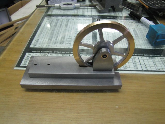
Elmer's Kimble engine has been on my to-do list for quite a while, and have literally been nagging at me to be built.

I can't seem to find any other build logs on it, and have only found one short Youtube video of one, so this is a bit of a journey into the unknown. The engine seems relatively straight-forward to build, but thinking through the processes, there are a couple of potential gotcha's - most notably that everything thing must be kept very square to prevent binding.

I have found one measurement wrong on the plans so far as well. The sizes for the mortise and tenon joint on the vane shaft does not match... A 1/4" tenon will not go into a 3/16" mortise, so those sizes I'll adjust as needed.

As usual, I'll be using whatever material I have on hand during the build - and will deviate a little from the plans in areas where dimensions does not matter.

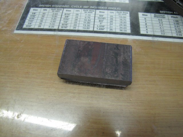
I started on the sub-base and base today. The plans call for a 1/8" sub-base and 1/2" base, so I settled for two bits of 10mm hot rolled steel bar :big: :
normal_IMG_3387.JPG

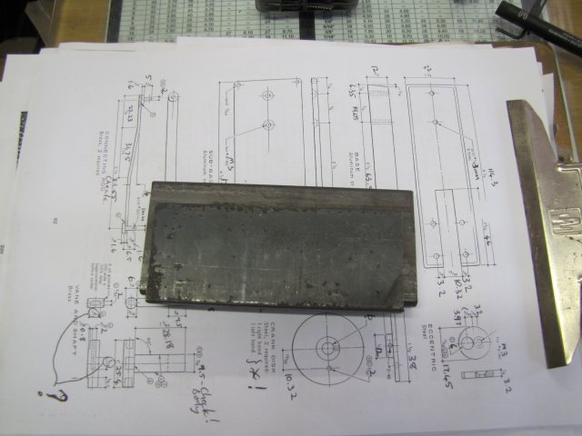
The thicknesses are not important - as long as they are thick enough together to accommodate the flywheel swing.

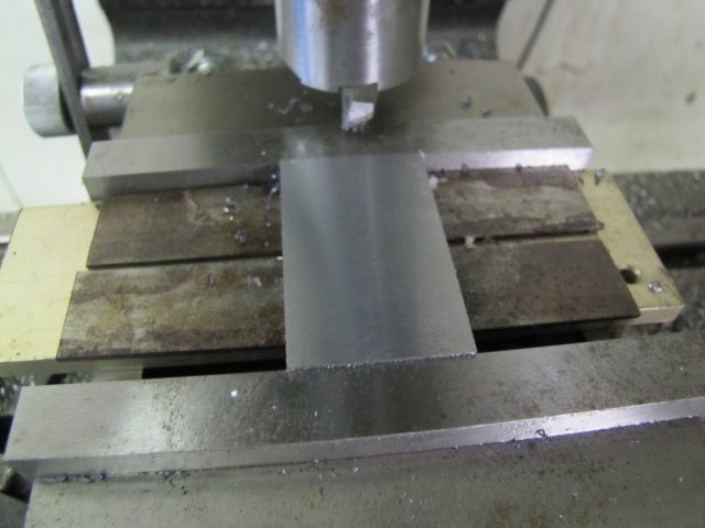
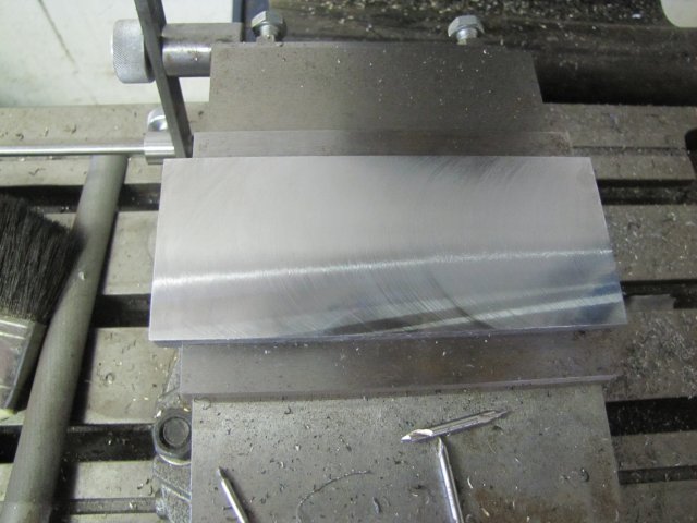
Both bits were sawed and then milled to size, and the flat faces roughly fly-cut to get rid of all the mill scale:
normal_IMG_3388.JPG


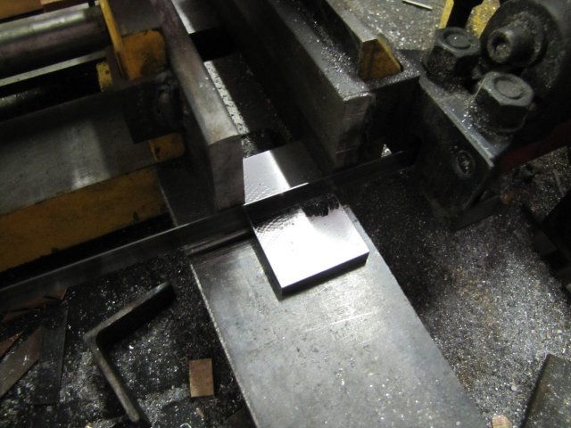
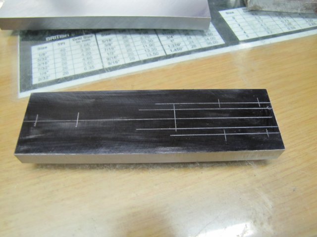
A bit of lay-out on the base:
normal_IMG_3389.JPG


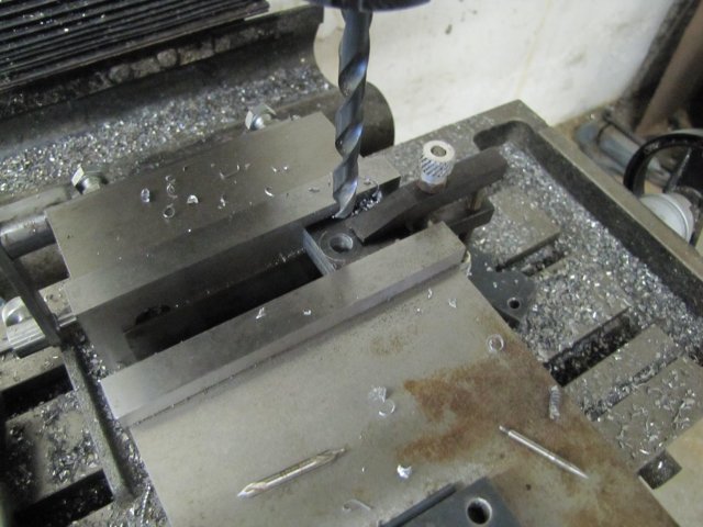
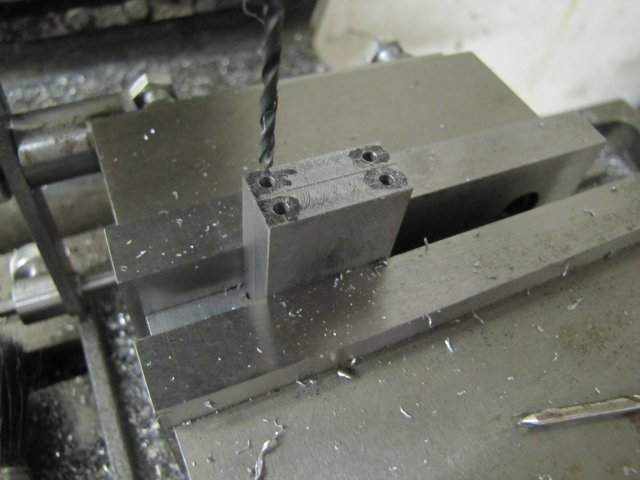
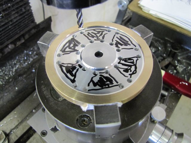
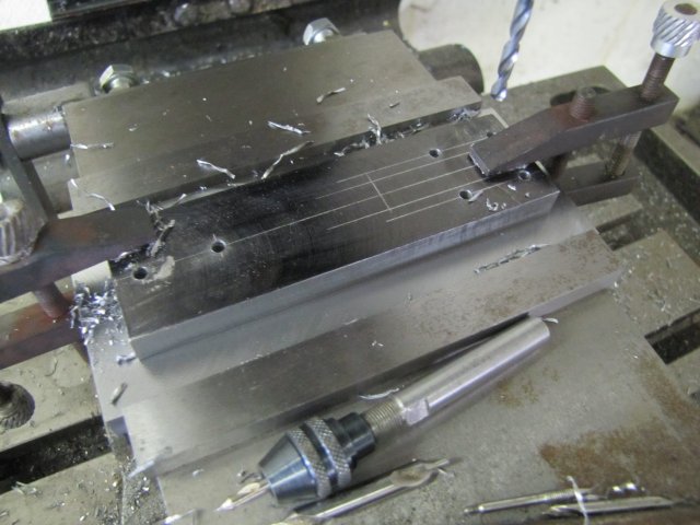
Then I clamped it to the sub-base and started drilling 3mm clearance holes for all the mounting bolts:
normal_IMG_3391.JPG


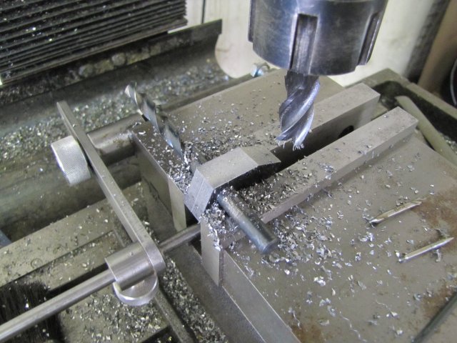
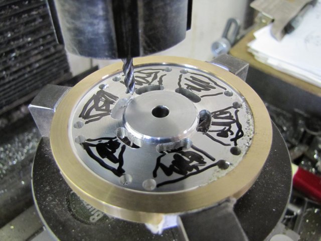
I wasn't feeling in the mood to mill out the entire flywheel cut-out, so I chain-drilled the end, pushed some pins through the holes to keep things matched up and then used the band saw to cut down the sides leaving about 0.5mm of metal to remove with the mill:
normal_IMG_3393.JPG

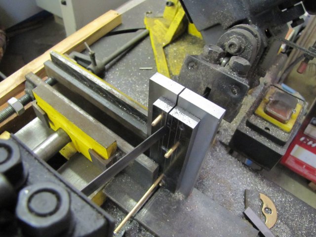
I just kept a careful eye on the cut to make sure it didn't stray too far. Because of the angle of the saw head, I had to stop early, and finish off the last short sections of the cuts with the saw in vertical mode.

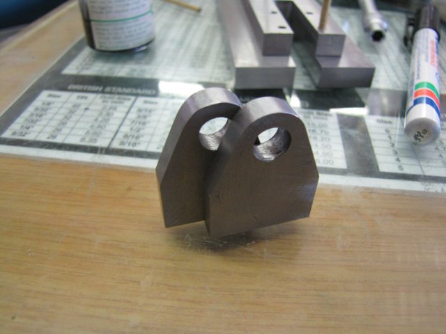
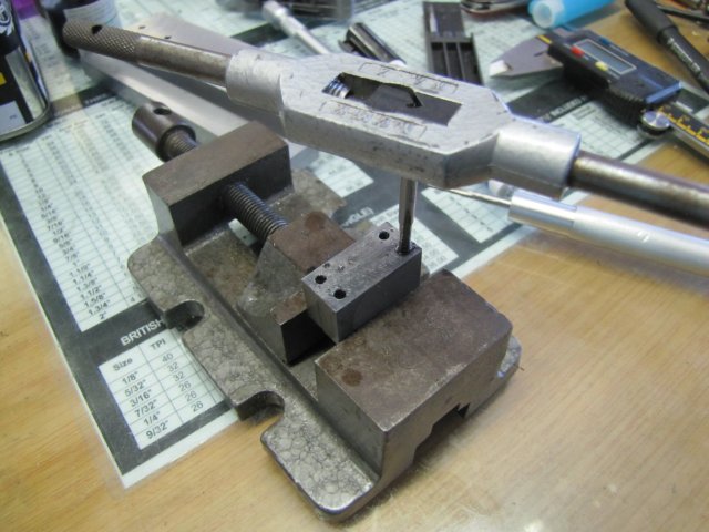
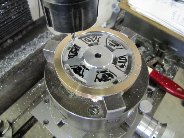
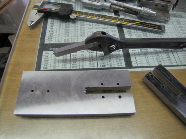
Now, who says a shifting spanner has no place in the shop ;D - I used a small one to break out the unwanted sections from the cuts:
normal_IMG_3394.JPG


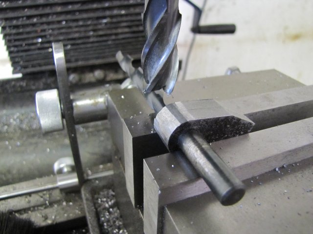
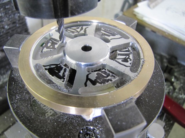
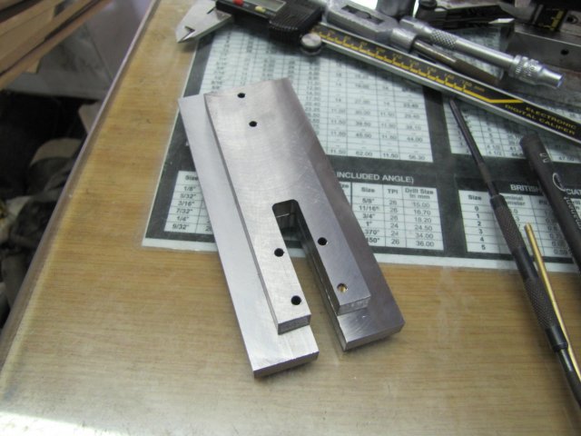
The cut-outs were cleaned up with a 4mm end mill; I just milled to split the mark-out line on the base:
normal_IMG_3395.JPG

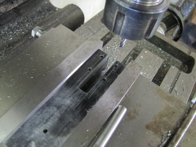
My 4mm end mills are too short to do both the base and sub-base at the same time, so I used pins to align the base with the sub-base again and used a sharp scribe to mark the sub-base off the milled-out section from the base. Then I just milled the sub-base to those lines as well.

Stopped here for today:
normal_IMG_3396.JPG


Regards, Arnold
 
Pulling up a chair. Looks good so far!
 
This is going to be another good one ...... I can just tell. 8)

BC1
Jim
 
No rest for the wicked!!!! ;D

You never cease to amaze me Arnold!!!!

Watching with interest again!!!

By the way it was -8 when i woke up this morning!
The dogs water bowl outside looked like an ice rink for all the varmin to use!!!!!
The dogs also kind of gave me the old hairy eyeball when they went for a drink!!! :big:

Andrew
 
Thanks Gents :) - this one might be a bit slow though, as 'tis the time of the year where a lot of merriment will happen!

:big: Andrew, the swarf magnets will do that if the water's frozen! It's getting up to a nice and balmy 32-35C here during the day now, but the nights are still surprisingly cool; this morning it was just 17C when I drove to work... I like that; nice & cool in the night, and a liveable temperature in the day. Once it hits 37C I stay out of the shop though :big:

I stole a couple of hours in the shop after work today, and started on the bearing columns. The plans call for 1/4" thick columns, and while I have some 6mm aluminium plate, I decided to rather make them from steel as well. The base will be painted, and keeping the material the same will save some headache when it comes to that. The columns need to be fairly close in thickness, as they will have the flywheel between them, and cranks and linkages on the outsides. I used some more of that 10mm hot-rolled bar:
normal_IMG_3397.JPG


The edges were milled square and to size, one face fly-cut to get rid of the mill scale, flipped in the vise, and then I hogged down the thickness to 6.4mm with a 16mm end mill:
normal_IMG_3398.JPG


A 0.05mm fly-cut, and the ugly hog-marks were gone and the bit of plate at 6.35mm ;D:
normal_IMG_3399.JPG


Split the bit of plate down the middle on the band saw:
normal_IMG_3400.JPG

And then milled the sawn edges down to size.

One block was laid out and the two were then carefully clamped together - ensuring all edges matched up - and the lot clamped in the mill vise and drilled 8mm:
normal_IMG_3402.JPG

The main axle will be 6mm, but as it will be steel and the bearing blocks are steel as well, I decided that I'll add pressed-in phosphor bronze bushes.

The last step for today was drilling the columns 2.5mm to tap M3 later for the mounting screws:
normal_IMG_3403.JPG


Regards, Arnold
 
"........ a lot of merriment....." is that anything like drunk and disorderly? :big:

It's always such joy to see you hard at work Arnold....


Cheers!

BC1
Jim
 
Thanks Jim :big: - not too much drunk and disorderly; 2 weekends ago the bloke in the photo below got what was coming to him - that WAS a bit drunk and disorderly; you should have seen what my house looked afterwards :big: - but it still looked better than what HE did ;) Yesterday I spent making sure he was looked after & properly attired, and then did some work behind the scenes to make sure the wedding march was started at the right time & that things would go right at the reception hall afterwards...:
normal_IMG_3406.JPG

The rest of the days just stop at tipsy & merry with a couple of drinks nearly every day with suppliers & business partners ;D. Us lot generally behave ourselves over Christmas, but New Year's might be a different story again :big:.
I think I'm a sucker for doing things the hard way... - You know, work hard and play hard!

Managed a couple of hours in the shop today :)

I used the mill vise stop as a kind of parallel to get a good angle on the bearing blocks (the bottom corners of the blocks actually rests on top of the vise stop bar), milled off the angle, flipped the blocks over & repeated:
normal_IMG_3421.JPG


Then milled the tops close to round:
normal_IMG_3422.JPG


A quick bit of file-work smoothed off the milled facets:
normal_IMG_3423.JPG


Tapped the bases M3 for the mounting holes:
normal_IMG_3424.JPG


Turned up a couple of press-fit phosphor bronze bushes:
normal_IMG_3425.JPG


Then started on the flywheel. I had a ring of phosphor bronze left over from the Coomber engine, so used that for the flywheel rim. One side and the rim was already true, so I just used two 8mm toolbits to offset the rim to allow me to turn it down to thickness - of course, removing the toolbits before starting up the lathe!:
normal_IMG_3426.JPG


After a bit of turning and boring, I had the flywheel rim:
normal_IMG_3428.JPG


Then I turned a bit of 70mm diameter aluminium down for a light press fit for the rim (0.02mm over size)- I had to wait a bit for it to cool down before the final finish pass, as I didn't want it to shrink down too much after machining:
normal_IMG_3430.JPG


I just left the rim outside in the sun for a couple of minutes; it was a searing 38C here today and the sun was beating down mercilessly, so that heated the rim quite enough to allow me to lightly, but quickly tap it into place on the aluminium, and once it cooled it is staying very much put. A careful clean-up on the rim and a face-off and I left things like that to go inside for a bit of time with the air conditioner. :
normal_IMG_3432.JPG


I did snap a photo of the base with the bearing blocks mounted; at least that's starting to come together now:
normal_IMG_3434.JPG

The parts just need a final clean-up to remove the last tool marks and a ding on the sub-base that I haven't noticed before, then some paint.

Regards, Arnold
 
Thanks David :)

Had a bit more shop time after work today :)

The flywheel-in-making was still sitting on the lathe as I left it Sunday, so I drilled and reamed it for the axle, trepanned the face to thin the web and then flipped the whole lot around in the chuck, using bits of cardboard to prevent damage to the finished rim:
normal_IMG_3435%7E0.JPG


Then I faced off the excess aluminium, and trepanned this side as well:
normal_IMG_3437.JPG


Next up will be a bit of work on the rotary table, but I have to calculate a couple of angles and offsets first...

Regards, Arnold
 
Shaping up to be a nice looking flywheel Arnold.

Brock
 
Thanks Brock :) I hope today's update doesn't disappoint!

After a merry week, it was nice to get to the shop today.

I first did a C-o-C, then decided on an end mill size and then added a's, b's, thetas and so on, then used sines, cosines and other stuff to make some calculations:
normal_IMG_3441.JPG

::) Yes, yes, I know... Boring math stuff; I'm a sucker for punishment ;D - but then again, it's really not that hard to do, and very useful 8)

On to machining then. I screwed the chuck to the rotary table and centered it on the mill with a 6mm bar chucked up - close enough for flywheel webs:
normal_IMG_3443.JPG

The X and Y hand wheels were zeroed here, and I just kept notes on the "boring maths page" (BMP from now on!) to remember which way I was cranking to compensate for backlash.

Then I drilled a bunch of 3.5mm holes according to the BMP:
normal_IMG_3445.JPG

I want to finish off the webs with a 4m end mill, so I used the 3.5mm drill as it leaves a bit of lee-way for error, and can just be drilled without using a center drill (or even better a spotting drill) for each location. If the 3.5mm drill wanders a tiny bit, that's OK.

Next I marked out the sections that must be milled out - just to help prevent a brain-fart later:
normal_IMG_3446.JPG


And a-milling-we-went. First the insides radial edges closest to the hub, with Y offset for the radius and feeding the rotary table between angles - taking the readings off the BMP; 1mm deep Z for each pass requiring 4 passes per slot; no use to hog things out, as that could just end in heartache or lots of "bad" words from a variety of different languages - or both:
normal_IMG_3447.JPG


The outside radial edges followed using the same method:
normal_IMG_3448.JPG


Up to now, everything was done from the mill table's X zero point with only Y feeds for offsets. For the next step, I once again referred to the BMP, offset the mill table in X and Y accordingly, dialed in the needed angle on the rotary table, and started on the straight sections of the webs - with feed on Y only:
normal_IMG_3449.JPG


More reference to the BMP, other offsets on the mill table, and the last cuts were done:
normal_IMG_3450.JPG


One side of the flywheel rim was still sharp from previous machining, so I mounted a bit of 6mm silver steel in the collet chuck on the lathe, pushed a bit of cardboard over it to protect and drive the flywheel hub, and then used a cone center with another bit of cardboard on the revolving tailstock center to mount the flywheel:
normal_IMG_3451.JPG


A quick lick with a file cleared off the burr on the rim, and then I just did some light file-work to get rid of burrs on the flywheel web. A final rub with some emery paper rolled into a cylinder removed some more toolmarks, and I ended up with this:
normal_IMG_3452.JPG

An OK-sort-of-looking flywheel. I wanted lightly tapered spokes, but not too lightly tapered either. Unfortunately, this is toward the "too lightly" side, so a lesson I can take forward. 4 degrees taper is too little on relatively short spokes like these :-[. I'm not about to use some form of put-on-tool to correct this; in fact the only put-on-tool I have that is suitable for this application is called "re-make" ::).

The BMP did get some additional scribblings on it through the process... Yes, I KNOW... It's still a "Boring Maths Page", but it did help :big::

In fact, if I had to be more mathematically precise, there would have been a lot more calculations involved - but this was good enough for the job on hand.

The flywheel does fit on the base though, and looks OK. I was thinking about painting the webs, but I have a hunch that will not be done; I'll decide about that once the base is painted:
normal_IMG_3453.JPG


Merry Christmas Everyone!

Kind regards, Arnold
 
And a very nice Christmas present you have made for yourself there Arnold.

Very nicely done. th_wav

But don't let Marv catch you doing it without his little flywheel program, that does all the working out for you, a real pleasure to use.


Best wishes for Christmas.


John
 
Thank you John :) Marv already caught me *club* - but I'll add in my defense that I Did try Marv's program. Unfortunately it works for only one hole around the hub for each spoke, which would not have worked in this instance. I could have run the program a second time to calculate the dual-holes around the hub though. That would still have left me to calculate the angle for machining the spoke sides manually...

Thanks Marv; i consider myself properly chastised :). I guess it's time I climbed into some programming for a change - as you know there's a bit more math than I showed, and I don't think that will be boring ;D

Thanks Robert :) I guess I'll have to test with future flywheels... This one has short spokes, but the large hub is needed for the way the eccentric is to be mounted.

Well, zero shop time today - I lazed about and stuffed my pie-hole all day ;D

Kind regards, Arnold
 
Yes, it's my turn to be chastised. After I looked again I realized that you didn't have a single hole at the base of the cutout "triangle" and my program wouldn't have worked for what you were doing.

Hmm, I wonder if I should write a program for that case? It's a very specialized case and there wouldn't be much call for the program. I'll think on it.
 
Marv, no need to feel chastised :). Like you said, I don't know if you should spend time on doing a program for this scenario. Your current flywheel program is just fine, and I haven't seen many (if any) flywheels with a similar layout to this one. Elmer's plans does give dimensions for the flywheel for the Kimble, so anybody wanting to build it has that to go on; I'm just bumbling along doing things my own way in areas where deviation from the plans does not matter.

On the other hand, if you do write it, it might get used - people are always on the look-out for different flywheel designs, and this does provide an option. I haven't looked at the source for "FLYWHEEL" yet, but it might be fairly easy to adapt the existing code; the inner holes' position and arc calculation would be pretty much the same as that for the outer holes. The calculation for getting the angle for machining away the sides would be pretty much the same too - unless I'm overlooking something blindingly obvious - which happens often!

Kind regards, Arnold
 

Latest posts

Back
Top