arnoldb
Well-Known Member
- Joined
- Apr 8, 2009
- Messages
- 1,792
- Reaction score
- 12
Today's little bit...
From this point on, I'll work a bit slower, as this is the start to the more difficult parts of the build.
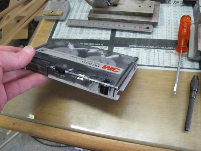
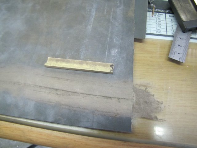
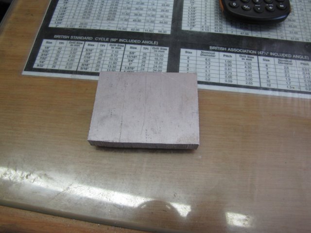
First, the engine block. It must be 3/8" (9.53mm) thick. I have some 10mm thick aluminium I could have used, but that bit is from extruded bar and very gummy to machine and tap, so I rather dug a bit of harder 12mm aluminium out of the stock bin:
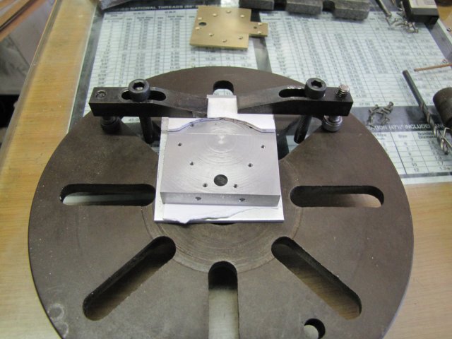
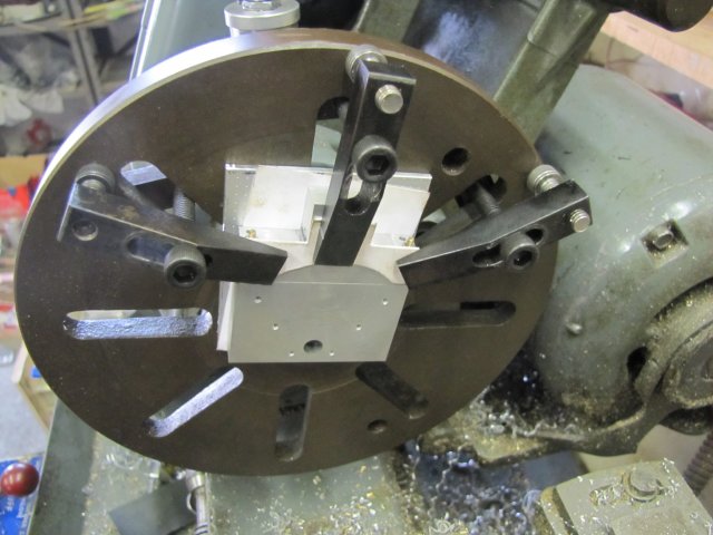
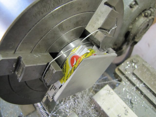
That was then milled square and to size on all edges. As I felt in the mood for some lathe work, I set it up in the 4-jaw on the lathe - just centered by eye and using a bearing shell as a parallel to the chuck body. Some strips of aluminium drinks can were used to prevent chuck marks, and I used wire to bind down the parallel so that it wouldn't rattle around and damage the chuck face if it did happen to come loose:
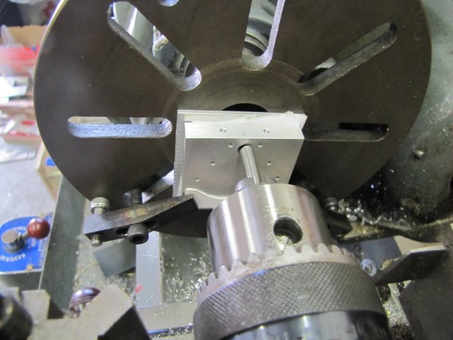
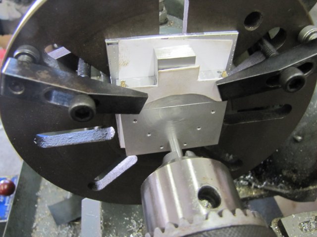
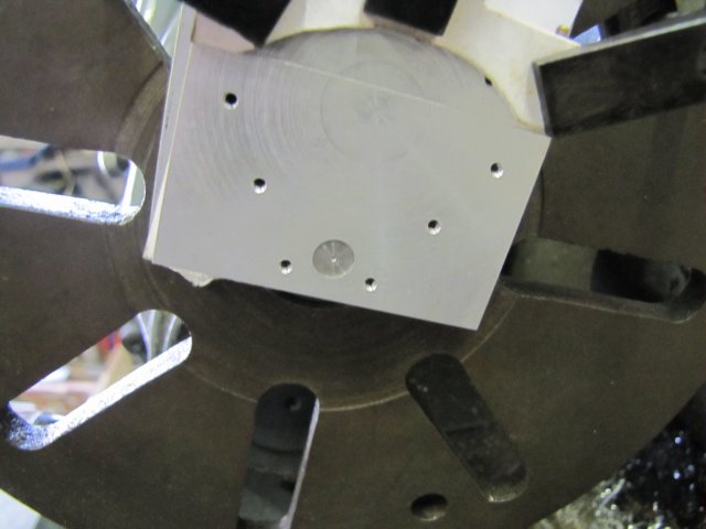
Faced one side smooth, flipped the block around in the chuck, and faced the other side down to thickness:
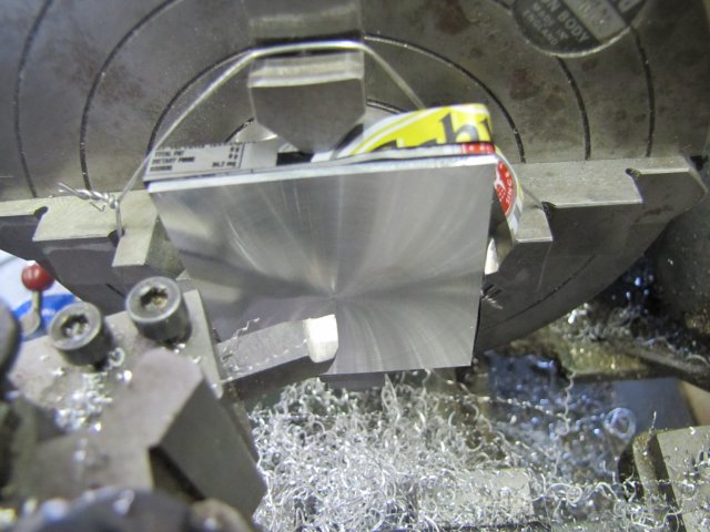
There's a slightly rough bit close to the center, but it does not matter, as that's in an area that will be machined away later.
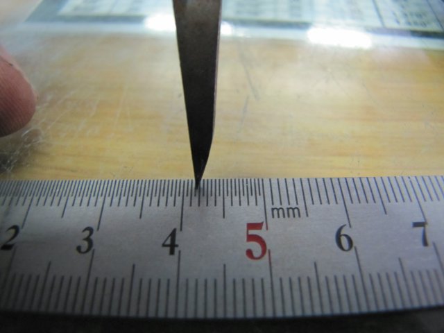
The block needs to be very parallel, and a check with a micrometer gave me less than 0.005mm (that's 2/10ths of a thou) difference measured in a couple of different locations. My old girl (ML7) may be 40 years old, but she can still do it ;D
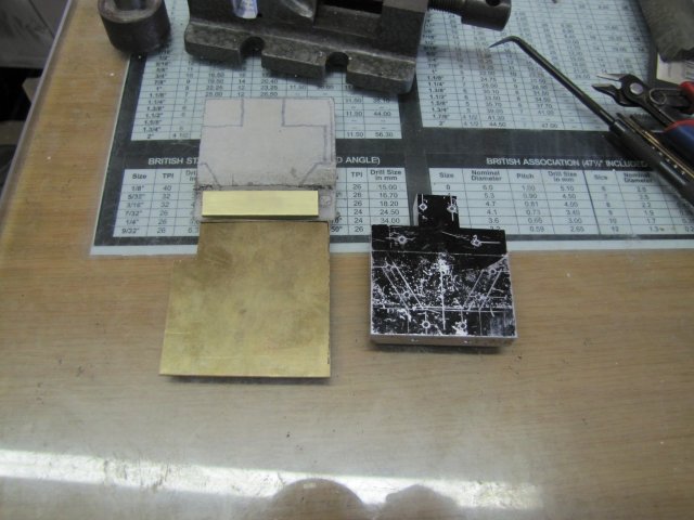
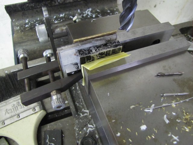
Some quick marking out for bits that needed to be milled away and the double marking across is 1mm thick where it must be cut with a slitting saw later:
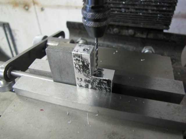
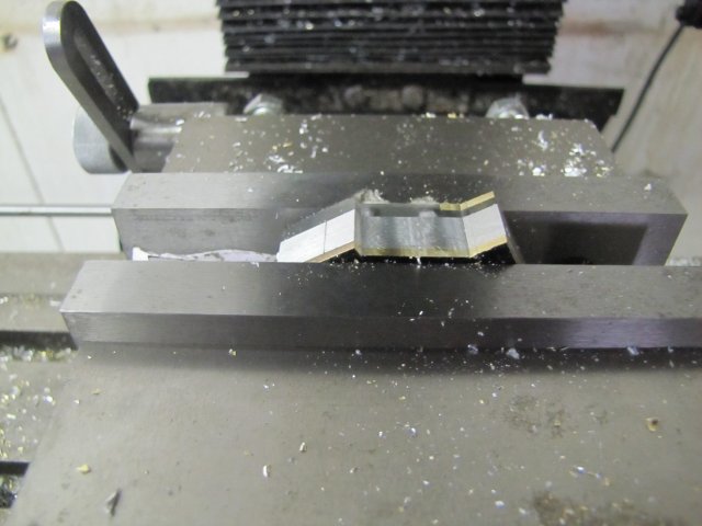
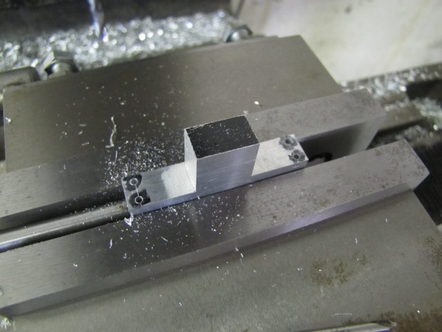
Cut-outs milled away; just hogged it down close to size with the 16mm end mill and then a light final pass either side to clean it up:
I bought a 5mm edge finder quite a while ago, but it was a bit rough and sticky and didn't work well. Last week one evening I gave it a thorough wash-out with methylated spirits to get rid of the sticky oil that was used on it, mixed some Brasso with thin oil and lubricated the running face with that concoction and gave it a bit of a run, before once again washing it out thoroughly and just giving it some light machine oil. Used it today for the first time, and it works beautifully ;D :
At 800RPM it wiggles around a bit, then smooths out, and then suddenly kicks out positively. On the mill dials this was exactly on the same reading each time; I'll test it's accuracy more thoroughly at another time.
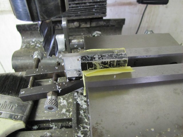
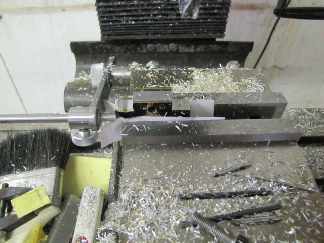
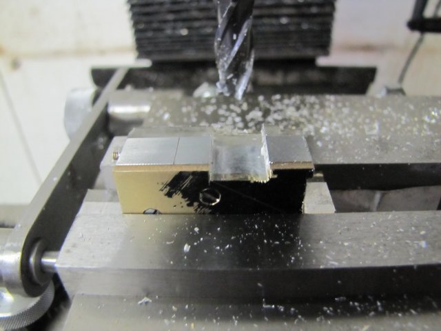
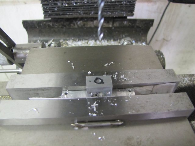
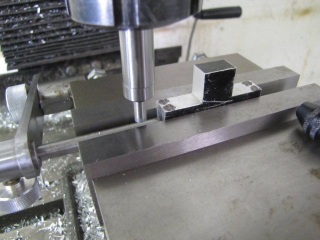
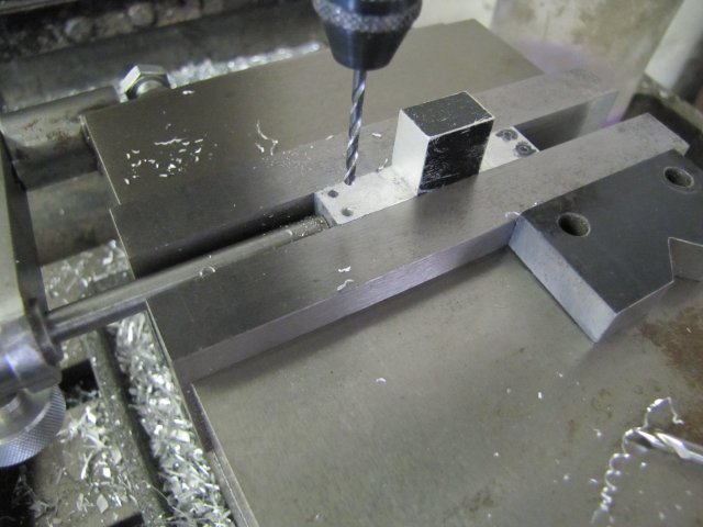
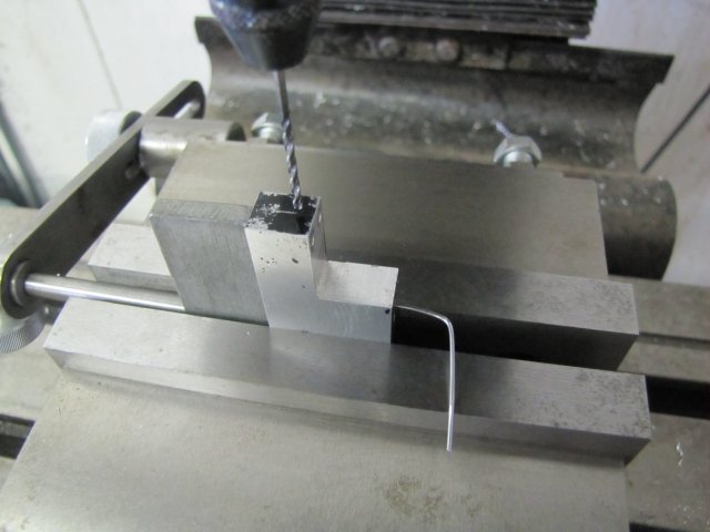
I used the vise stop and the mill's dials to coordinate drill the mounting holes 1.6mm to tap M2 later:
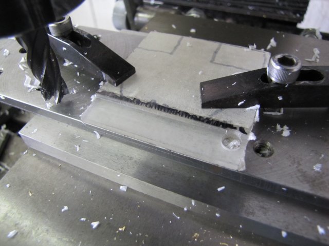
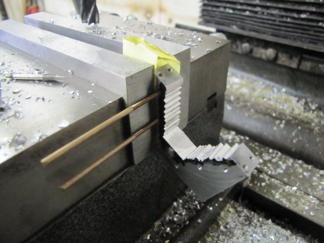
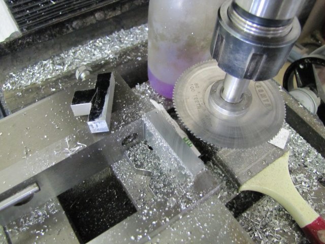
Then I slit the top section off:
As I didn't change the vise stop or dial zero-rings when slitting, I just used the same settings and readings to drill 2mm clearance holes through the top:
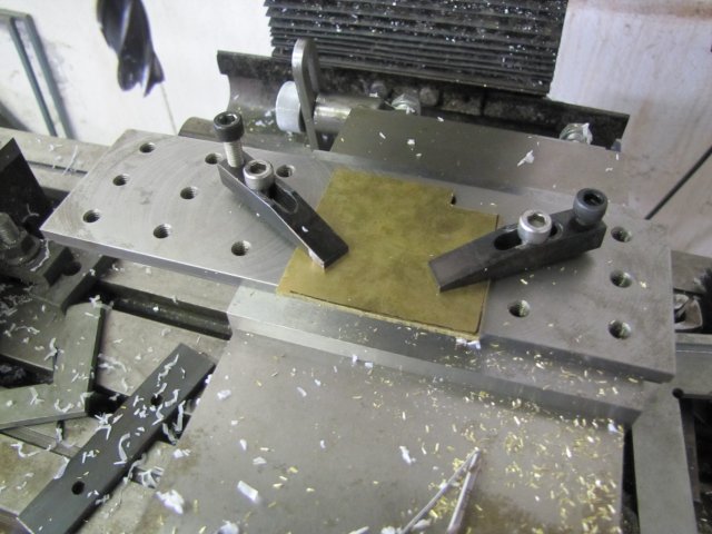
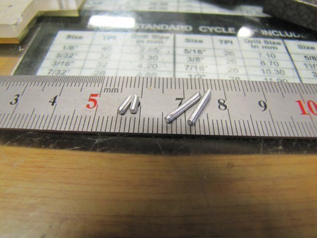
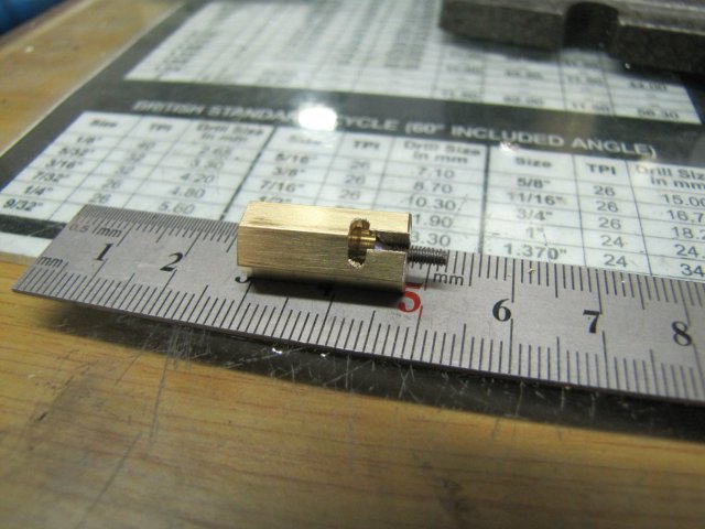
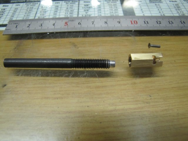
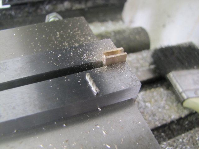
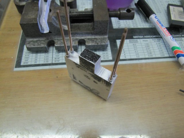
Next I tapped the holes in the bottom section. I don't have long enough 2mm screws, so out with some bits of threaded rod:
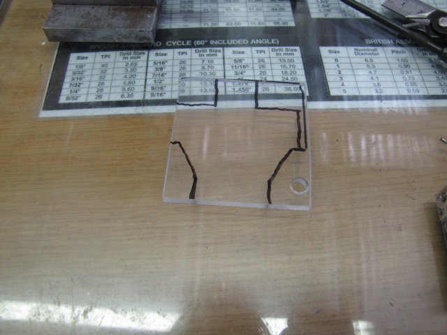
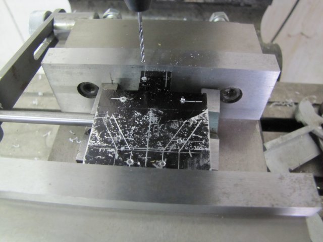
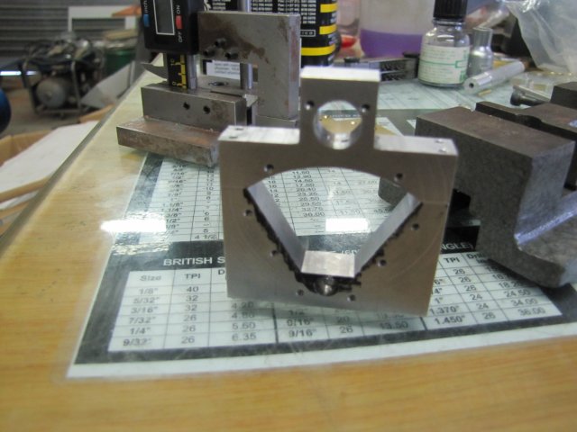
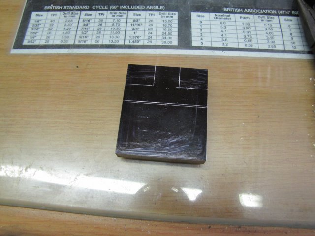
More marking out. The engine block layout on the plan is quite busy, and it's easy to get some measurements wrong. In addition, the tangent sections are a bit difficult to lay out, as Elmer didn't give easy measurements to get to them. As you can probably see, I ended up with a bit of a discrepancy in the thickness of the tangent sections - a combination of trying to manipulate the protractor and forgetting to compensate for the scribe tip's thickness:
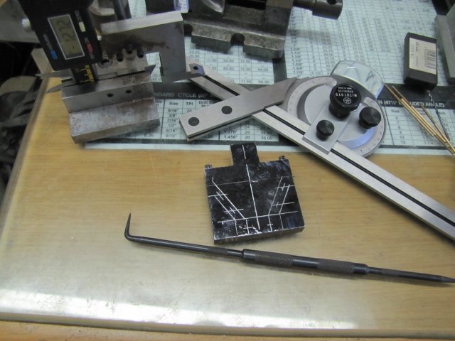
Fortunately, the error is not a biggie; I stopped quite a while ago scribing deep lines on the work, as that's too difficult to get rid of later. Both the scribe and the height gauge tips need a bit of sharpening as well; that's why the lines appear so thick. I'll be using the vise stop to mirror the work as I go, so I only need good layout on one side anyway.
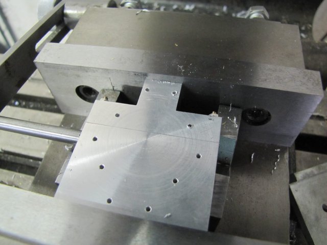
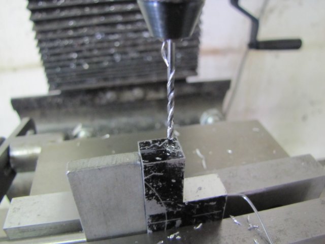
I then started drilling the 1.6mm holes for mounting the "cylinder" covers; these needs to be tapped M2 later. Simple process to get the mirroring; locate a hole on the marked-out side and drill, then flip the workpiece end-over end and drill the mirrored hole on the unmarked side. Here it is ready to be flipped to drill the last hole:
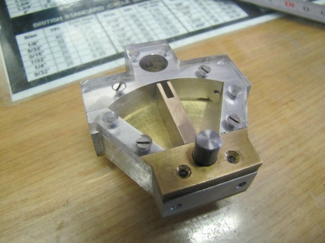
After drilling that last hole I stopped for the day. I'm torn between making both the covers from some 2mm brass plate I have, or making the one cover from perspex so that the vane can be seen in operation. The only suitable perspex I have is 3mm thick, and I'll have to check whether this will fit. In addition, the vane shaft uses the holes in the covers as part of its bearing, so if I make a perspex one, I'll have to think up a way to insert a bush in it, and that's not so easy, as the inside part must be very flat as it is part of the sealing surface...
Time to think a bit...
Regards, Arnold
From this point on, I'll work a bit slower, as this is the start to the more difficult parts of the build.
First, the engine block. It must be 3/8" (9.53mm) thick. I have some 10mm thick aluminium I could have used, but that bit is from extruded bar and very gummy to machine and tap, so I rather dug a bit of harder 12mm aluminium out of the stock bin:
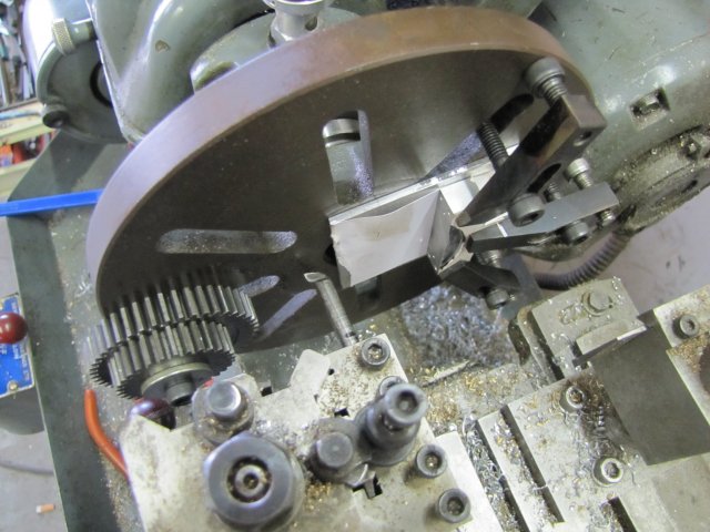
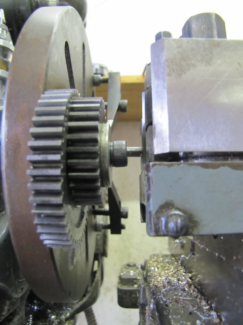
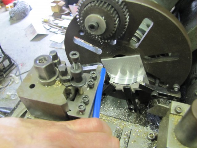
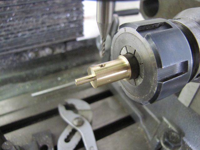
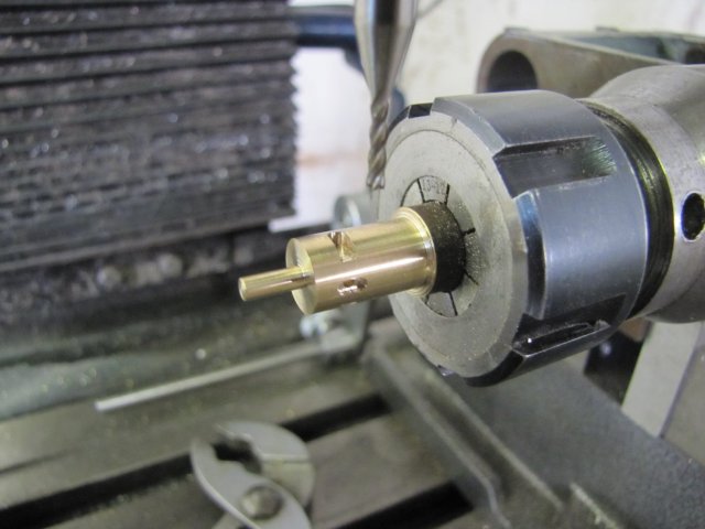
That was then milled square and to size on all edges. As I felt in the mood for some lathe work, I set it up in the 4-jaw on the lathe - just centered by eye and using a bearing shell as a parallel to the chuck body. Some strips of aluminium drinks can were used to prevent chuck marks, and I used wire to bind down the parallel so that it wouldn't rattle around and damage the chuck face if it did happen to come loose:
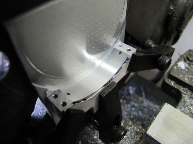
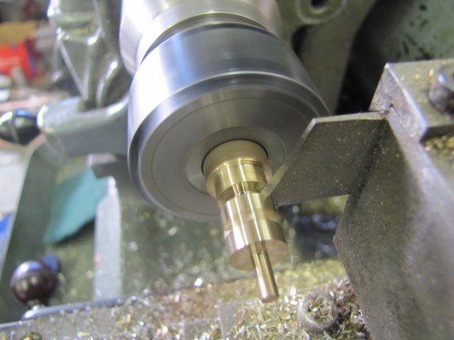
Faced one side smooth, flipped the block around in the chuck, and faced the other side down to thickness:
There's a slightly rough bit close to the center, but it does not matter, as that's in an area that will be machined away later.
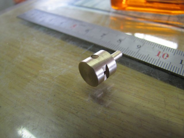
The block needs to be very parallel, and a check with a micrometer gave me less than 0.005mm (that's 2/10ths of a thou) difference measured in a couple of different locations. My old girl (ML7) may be 40 years old, but she can still do it ;D
Some quick marking out for bits that needed to be milled away and the double marking across is 1mm thick where it must be cut with a slitting saw later:
Cut-outs milled away; just hogged it down close to size with the 16mm end mill and then a light final pass either side to clean it up:
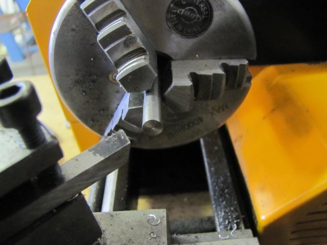
I bought a 5mm edge finder quite a while ago, but it was a bit rough and sticky and didn't work well. Last week one evening I gave it a thorough wash-out with methylated spirits to get rid of the sticky oil that was used on it, mixed some Brasso with thin oil and lubricated the running face with that concoction and gave it a bit of a run, before once again washing it out thoroughly and just giving it some light machine oil. Used it today for the first time, and it works beautifully ;D :
At 800RPM it wiggles around a bit, then smooths out, and then suddenly kicks out positively. On the mill dials this was exactly on the same reading each time; I'll test it's accuracy more thoroughly at another time.
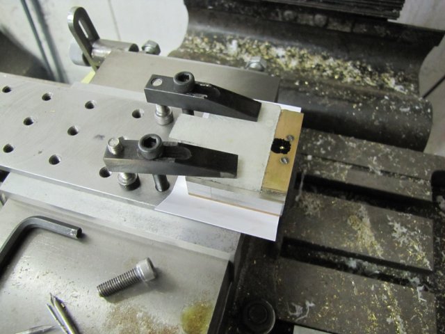
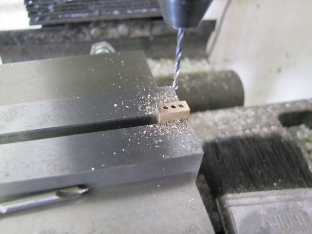
I used the vise stop and the mill's dials to coordinate drill the mounting holes 1.6mm to tap M2 later:
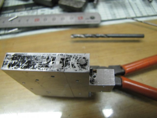
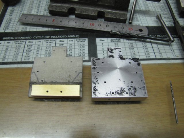
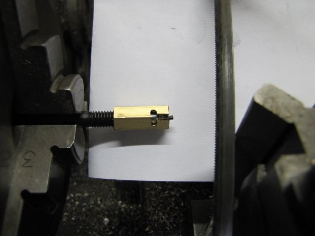
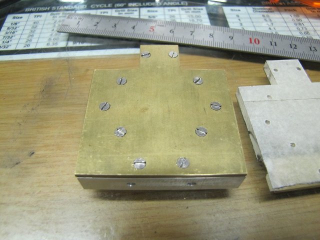
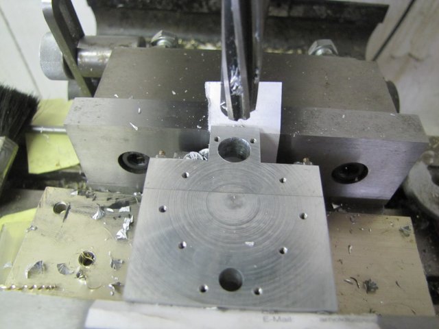
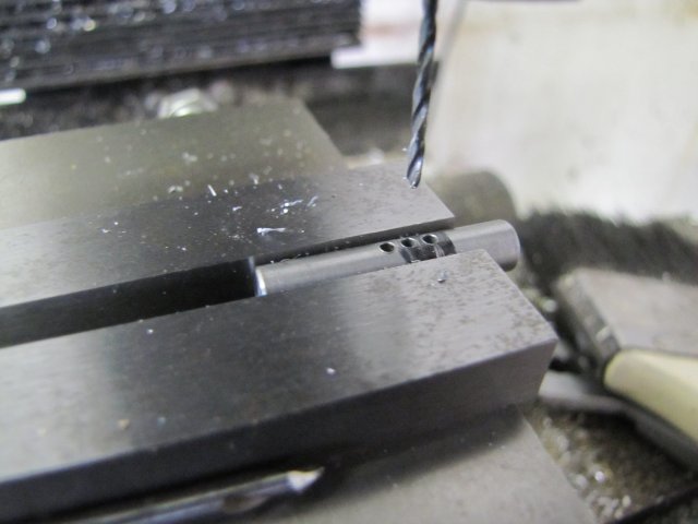
Then I slit the top section off:
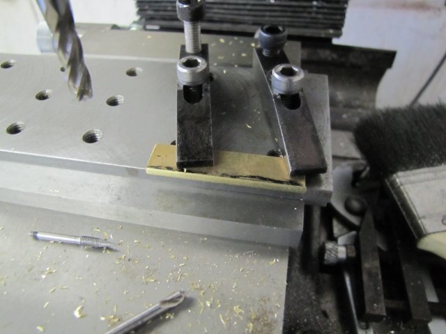
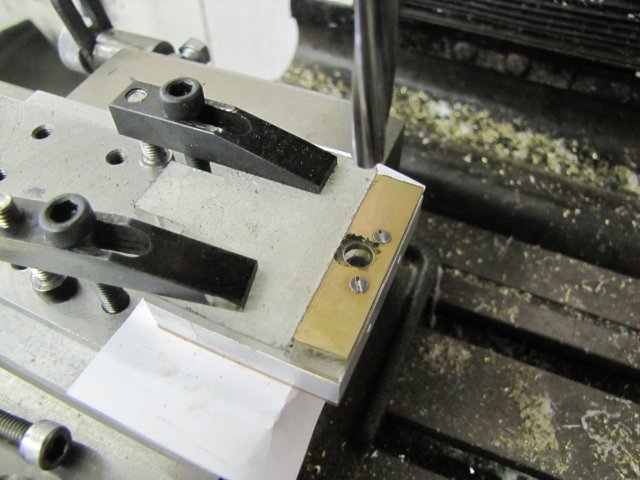
As I didn't change the vise stop or dial zero-rings when slitting, I just used the same settings and readings to drill 2mm clearance holes through the top:
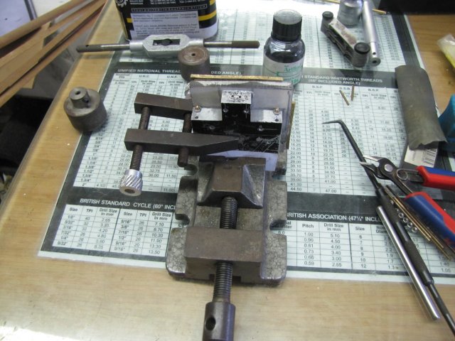
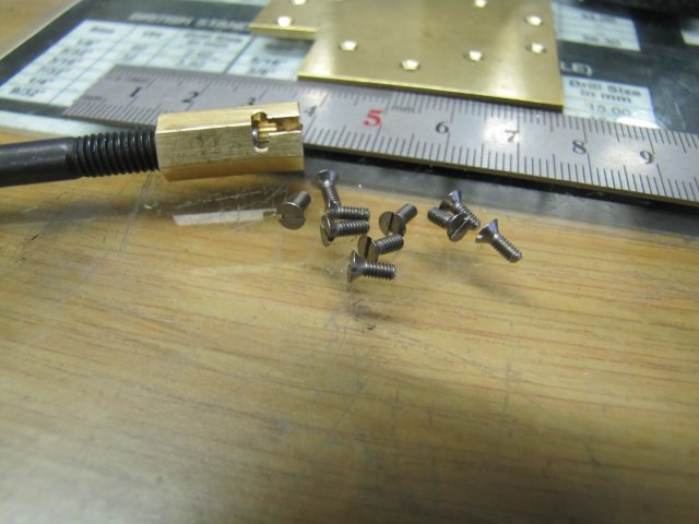
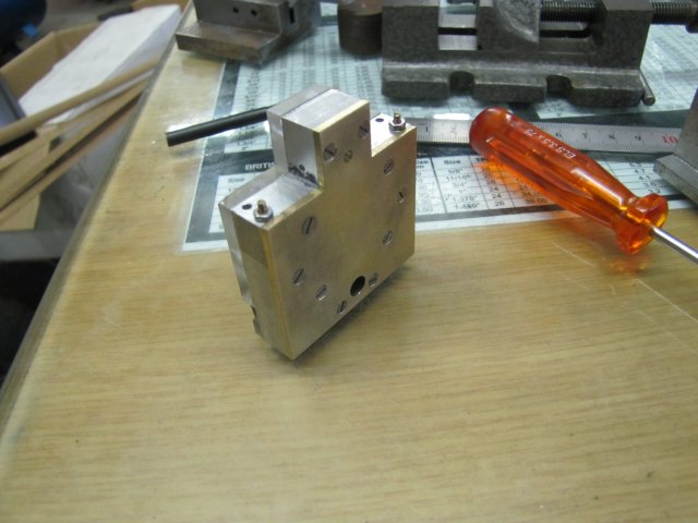
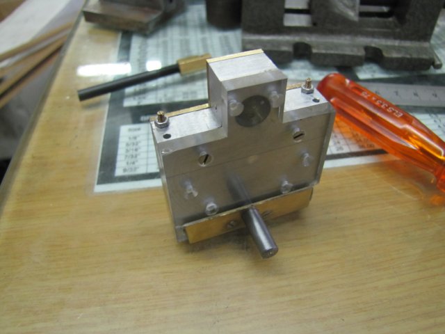
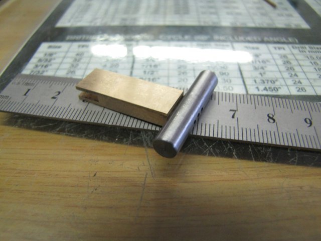
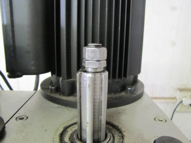
Next I tapped the holes in the bottom section. I don't have long enough 2mm screws, so out with some bits of threaded rod:
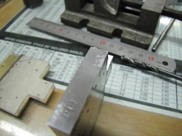
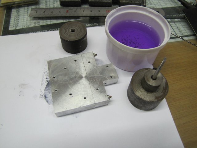
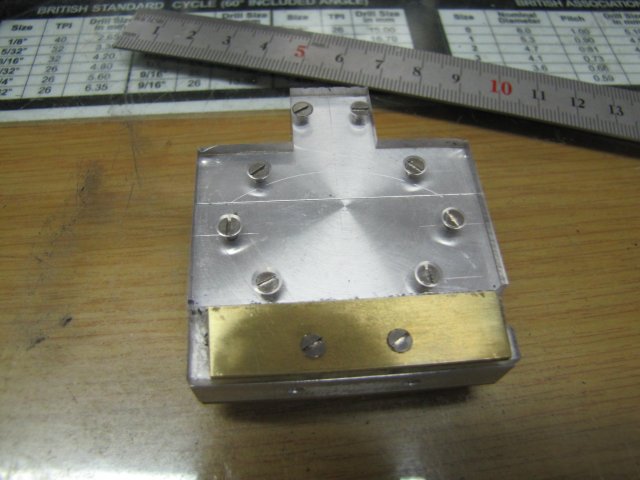
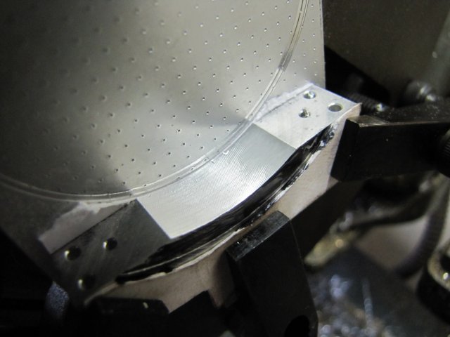
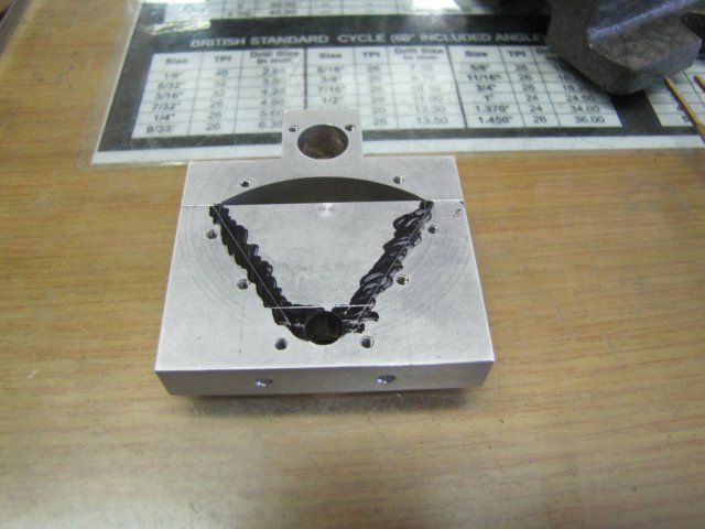
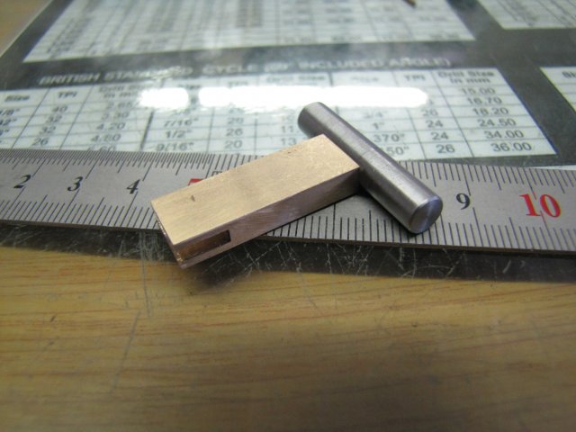
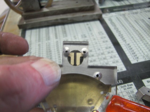
More marking out. The engine block layout on the plan is quite busy, and it's easy to get some measurements wrong. In addition, the tangent sections are a bit difficult to lay out, as Elmer didn't give easy measurements to get to them. As you can probably see, I ended up with a bit of a discrepancy in the thickness of the tangent sections - a combination of trying to manipulate the protractor and forgetting to compensate for the scribe tip's thickness:
Fortunately, the error is not a biggie; I stopped quite a while ago scribing deep lines on the work, as that's too difficult to get rid of later. Both the scribe and the height gauge tips need a bit of sharpening as well; that's why the lines appear so thick. I'll be using the vise stop to mirror the work as I go, so I only need good layout on one side anyway.
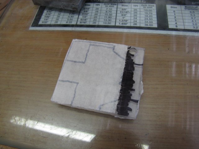
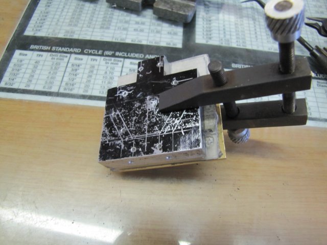
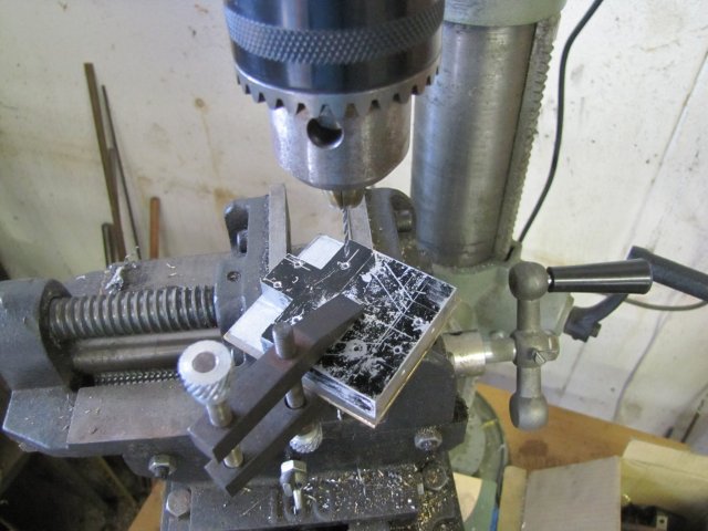
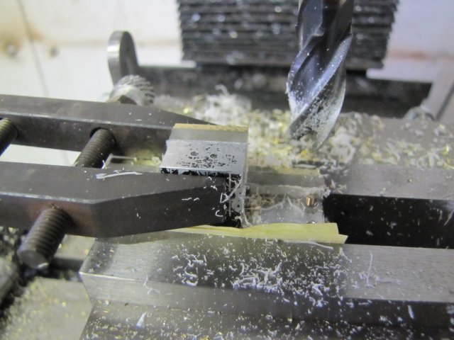
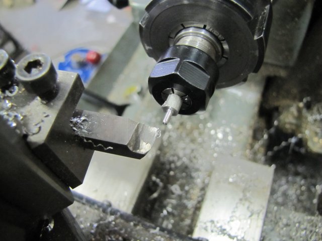
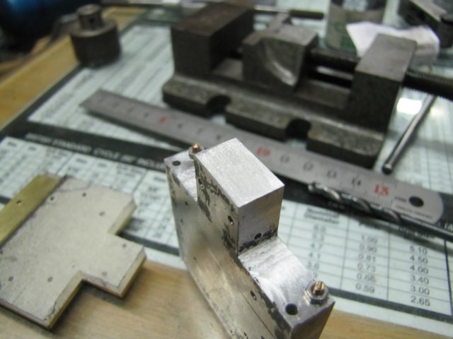
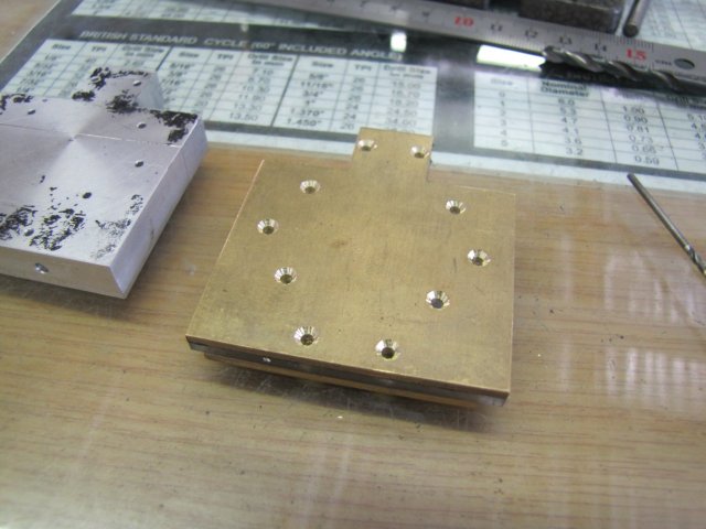
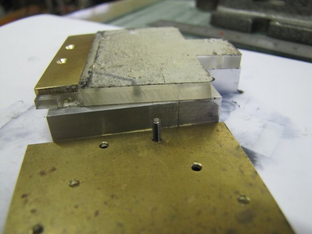
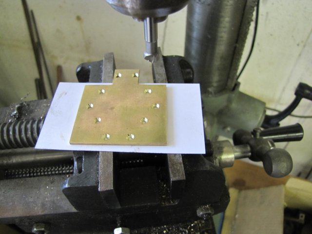
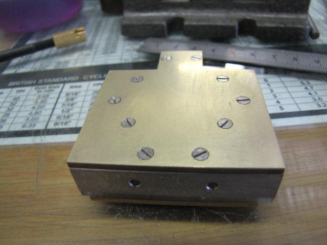
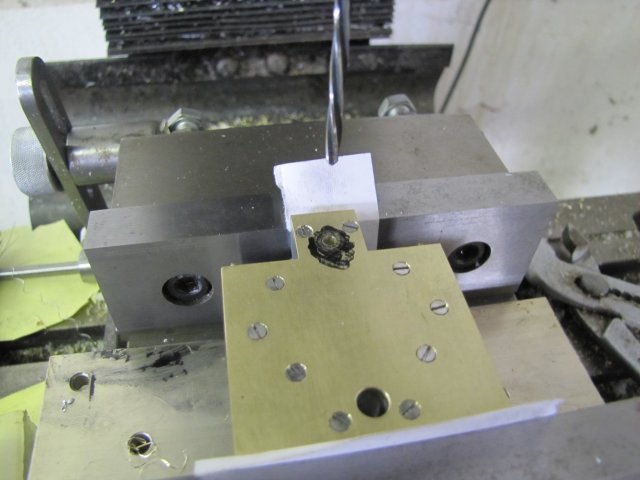
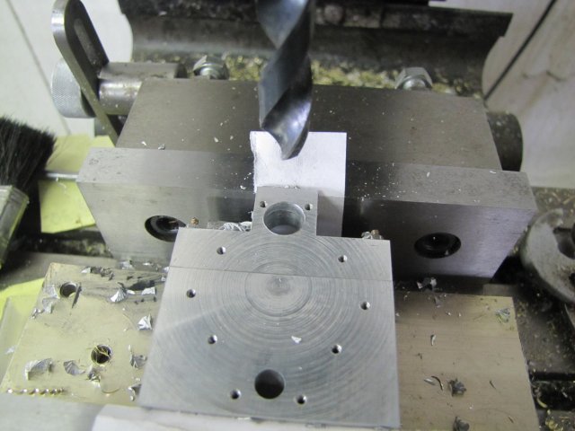
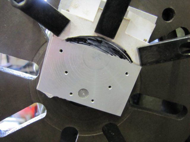
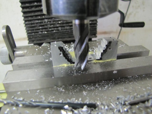
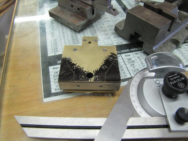
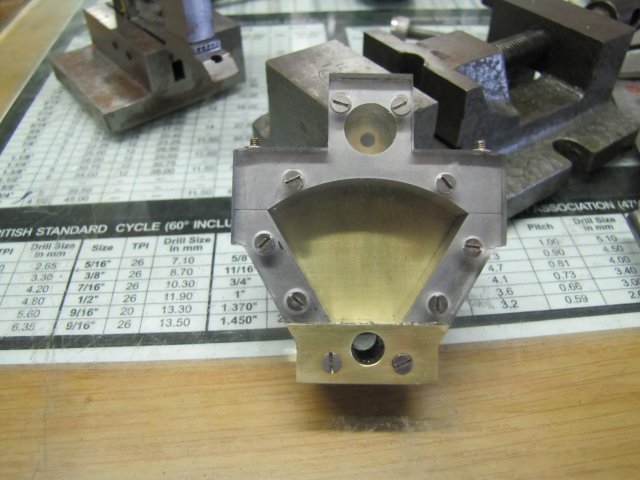
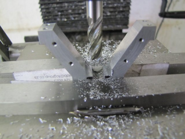
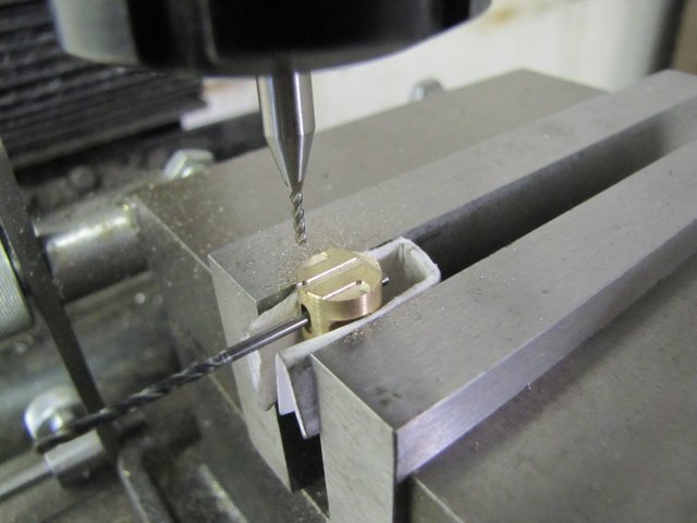
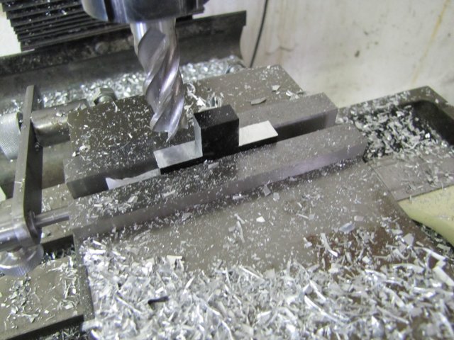
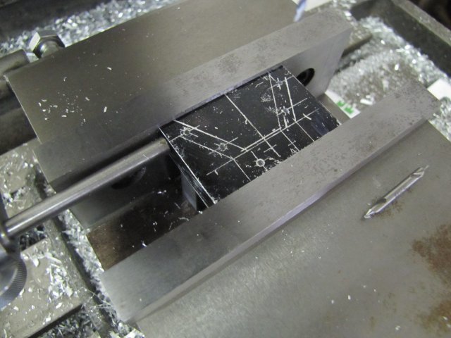
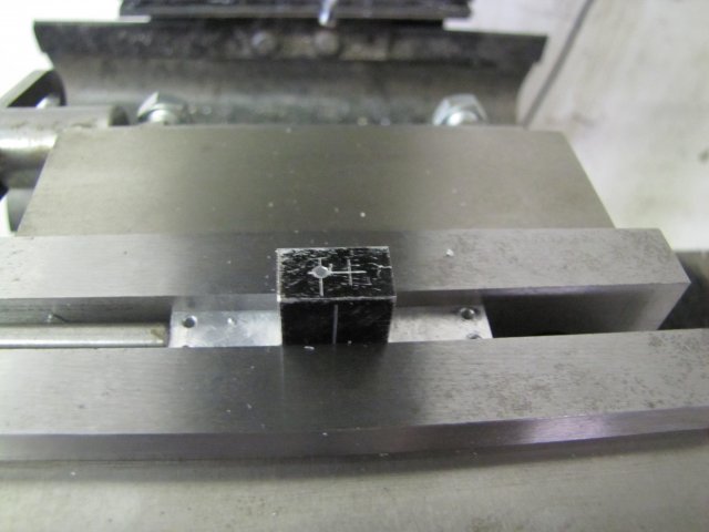
I then started drilling the 1.6mm holes for mounting the "cylinder" covers; these needs to be tapped M2 later. Simple process to get the mirroring; locate a hole on the marked-out side and drill, then flip the workpiece end-over end and drill the mirrored hole on the unmarked side. Here it is ready to be flipped to drill the last hole:
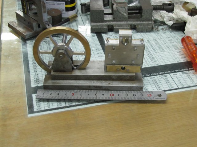
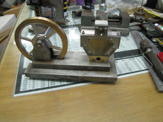
After drilling that last hole I stopped for the day. I'm torn between making both the covers from some 2mm brass plate I have, or making the one cover from perspex so that the vane can be seen in operation. The only suitable perspex I have is 3mm thick, and I'll have to check whether this will fit. In addition, the vane shaft uses the holes in the covers as part of its bearing, so if I make a perspex one, I'll have to think up a way to insert a bush in it, and that's not so easy, as the inside part must be very flat as it is part of the sealing surface...
Time to think a bit...
Regards, Arnold
") Ken, I was once in Cape Town when it went up to 35... Camping in a caravan... High temperatures in CT is really unpleasant :wall:
Ken, I was once in Cape Town when it went up to 35... Camping in a caravan... High temperatures in CT is really unpleasant :wall: