Entablature Steam Pumping Engine

Home Model Engine Machinist Forum

Help Support Home Model Engine Machinist Forum:

This site may earn a commission from merchant affiliate links, including eBay, Amazon, and others.
Really nice work on a beautiful example of Victorian architecture in a steam engine. I'm anxious to see the crosshead when it's done

Cheers,
Phil
 
Thanks, Phil - it's always nice to hear things are going in the right direction!

You're right though - the crosshead has got to come out of the desk drawer and hit the machine again, but I'm wavering between that, the crankshaft or the pedestal corners next... :confused:
 
Ok, first things first - I hope you're all had a great Christmas, and will have a very happy New Year! ;)

Also, I've been very bad on taking pictures of progress so far as I've been grabbing machining time when I can, but not always when I've had a camera with me... :(

Where we're at now is that the crankshaft is done - machined from a very handily sized bit of gauge plate. The crank pin was turned first between centres, and then after rough milling, the main bearings turned. The finishing was face milling to get the tapers on the sides of the webs, and then hand filing and papering to blend these into the mains.

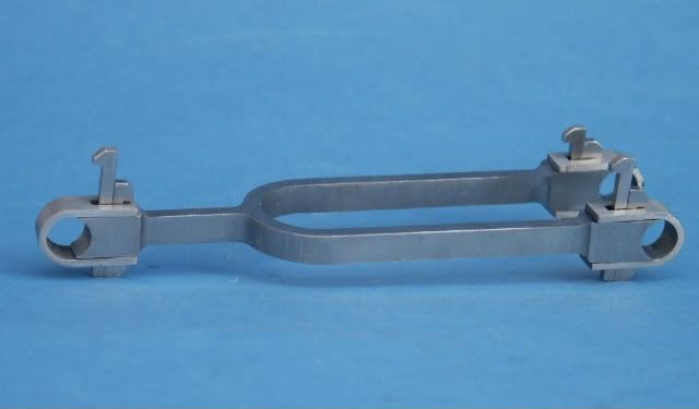
Also, I've started the con-rod. This took a reasonable amount of research and SW design, as I'd like it to reflect the full strapped design of the original, but not many details or proportions were in the plans. I'll try to post the SW image soon, but for the main part of the rod I started with a session on an Interact to produce the main profile, with a bit of mild 3D work in the centre for the radius. Then after knocking the back off (roughly and carefully) on a manual mill, I put it up between centres on a manual lathe, and am currently in the process of turning the centre profile - very gently though!

Will pay more attention, and take more pics soon, but feel free to ask for any info or pics! :)

Btw, couldn't help myself but drop in a pic of a little bit of 3D machining the Interact did a while back - corny but cute ;D

Dave

PIC_0025.jpg


PIC_0029.jpg


PIC_0030.jpg


PIC_0031.jpg
 
First progress of the New Year - hopefully we'll get this done before the years too far gone :rolleyes:

Here's one end of the connecting rod centre finished now. Mounted in the same way as before - 14mm 5C collet holding the top end, and half centre carrying the back, I machined a 2.2deg taper to blend the previous 4.5deg taper into the parallel mid point. This was the blended with 80grit emery cloth on a file, before working down to 400 and the 800 grit.

Second half tomorrow when I can find who's borrowed my radiussed tool steel bit that I used last time... :confused:

IMG_0580.jpg


IMG_0581.jpg
 
Good to see you making some more progress with this one. I had to do a similar conrod on my Benson though all the sections were rectangular so it could all be done on the mill.

Keep them comming

J
 
Cheers, Jason :)

Nearly time to break out the needle files for the wedge slots too - how long did yours take you to do?
 
I Like the insert tool that you are using; I have wanted to get one like that.

Nice work on the engine; thanks for sharing your progress.


Dave
 
They're very useful tools for getting into tight spaces, and will also so lightish roughing - highly recommended. I've had this one for about 12 years now, and even after modifying it to finish the inside of a BR2 crankcase it's still a blinder :)

Glad you like the progress too - thanks!
 
I took most of the material out by drilling several 1.4mm holes and then plunging with a 1/16" slotdrill in 0.010" steps and then finally attacked it with a file 1/8" square file that I ground two sides off so it was just the right width for the 1/16" slot and in effect had two safety edges.

PICT0336-1.jpg
 
I see I'm really late to this party. I could get a doctors slip though.:( Very, very beautiful work Dave. I'm certainly glad you jogged my memory about this build yesterday. And what's really nice is I'm not to blame for any of it. I'm positive Jason is right and he provided that link. Anyway he lives closer to you Dave. And for anyone who hasn't seen much of Dave's Solidworks creations? He's far too modest. The Victorian style of engine building have always amazed me due to the amount of artistic shaping the designers used. Form didn't follow function. Jason's Benson is another that has much less details added, but it was still done on the full size that weren't needed, but they were still used simply to help beautify an engine.

I'm curious though, I've only seen George Gentry's drawings in the older M.E's. Does anyone know his history? He was very talented, and I can't believe that the M.E. magazine was the only one to publish his work. He was much too late to have been a full size designer for the Victorian style of engines. Maybe a designer for the more modern types during the mid 20th century?

Pete
 
Last edited:
Pete - you may be right, but for sure you're a bad influence anyway on the project front - my list has expanded beyond all recognition with these plans you keep sending! :eek:
Good to see you on here again though - roll on a speedy recovery and getting that shop going again!

Nice work on that 'rod Jason - hopefully I'll have something similar in the not too distant future...

Anyway, roll on lunchtime machining - it's Edwards 5 cylinder heads on the CNC, and the second half of the 'rod on the lathe today ;D
 
Well here's a bit more machining, finally :D
The straps for the con-rod have been programmed in Gibbs, machined from gauge plate, and cleaned up - just waiting for the slots to be cut.
The first pic is the Gibbs screen to prove the tool paths - each colour is a separate op.

I do have to admit to cheating on the crosshead though. Its been sat in my desk draw, and nagging at me, so i thought it was time to push it forwards. What I have done though is finish roughing it out by 3D milling on the CNC - a wuss I know, but if it gets the engine done... :hDe:
I've milled a fixture for it to align it on a pair of hollow 5/16 dowels, and clamp it by two M6 cap head screws, and then hit it on each side to profile the radius of the cross shaft. Once the machining is done, then it should only be a quickly needle file and emery paper job to clean and polish it ready for it's bushes and fitting to the engine.

I should be able to post some more pics tomorrow on the finally milled crosshead, and hopefully also the start of the post for mounting the pivot of the governor lever - it's taking some tweaking in SW to get the proportions right, but it's close ;)

IMG_0582.jpg


IMG_0584.jpg


IMG_0585.jpg


PIC_0043.jpg
 
Ok, all the 3D milling on the cross head is done now. I pondered a final op with a 3mm cutter to chase out the corners a little further, but the proportions from the 6mm ball nose are looking good. I've had about an hour tonight with needle files to start blending the profile, and apart from one axis of machining, it's looking good and blending in nicely. I guess there was too much slop on the dowels, and I pushed it too far one way on the 'off' axis. Time now to keep going on the files and then emery paper, but personally the shape is great and I can't wait to get the 'rod' hooked up to it ;)

PIC_0045.jpg


PIC_0046.jpg
 
After several hours of needle filing, then emery cloth, and a trip to the buffing wheel, the first end of the crosshead is nicely blended in. I'm well happy with how it's coming up, but what feels like an eternity of fettling and blending all the different curves together is soul destroying - still, only half the main 'head and the pump lug to do now... :wall:

PIC_0048.jpg
 
This looks very nice! Great work! But is this element need to be machined from single piece of material ? Maybe easier way would be machine subparts on lathe and then weld them ?
 
That's one amazing build Dave, can't wait to see the end result! Beautiful work.

cheers, Ian.
 
Many thanks for the kind comments guys :)

Hinte, call it personal preference, but I prefer machining parts from solid if at all possible. Partly it's not having any joints in the part, but mainly it's that I like to push myself and improve my machining skills, and this part has certainly done that, lol. The filing in particular is soul destroying - glad it's nearly done!

I have fabricated parts in the past, either by welding or silver soldering, and there's always the issue of jigging the part correctly, and then remachining to remove any distortion, filing/papering to remove discolouration, and then sometimes the joint lines are visible... :mad:
 
Another lunchtimes machining, and the crosshead is progressing nicely after a quick session on the buffing wheel. There's a few corners still to get into with the emery paper, so bang goes my social life again tonight :wall:

For a bit of light relief I also turned the base of the governor lever post from 316. It the drawing it looks to be a single component, but to ease assembly I've split it into 2 pieces to make aligning the governor lever with both the main fly-ball shaft and also the throttle butterfly a little easier.

Hopefully tomorrow I'll get either the governor lever or the fork for it's pivot onto the mill ;)

IMG_0589.jpg


IMG_0591.jpg


Governor - 24-01-13.jpg
 

Latest posts

Back
Top