More than a few months later, this morning I was able to finish all the parts of Elmer's tiny in 1/4 scale. On with assembling the parts...
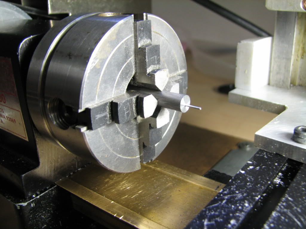
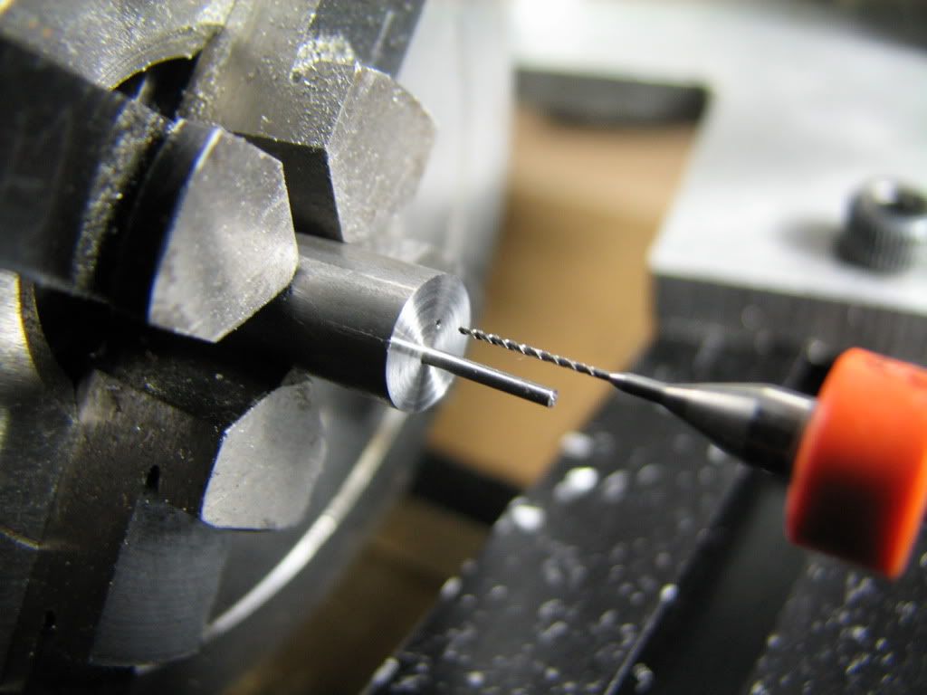
I had to machnine the airducts. Because the engine is so small, I have to supply the air through the base.
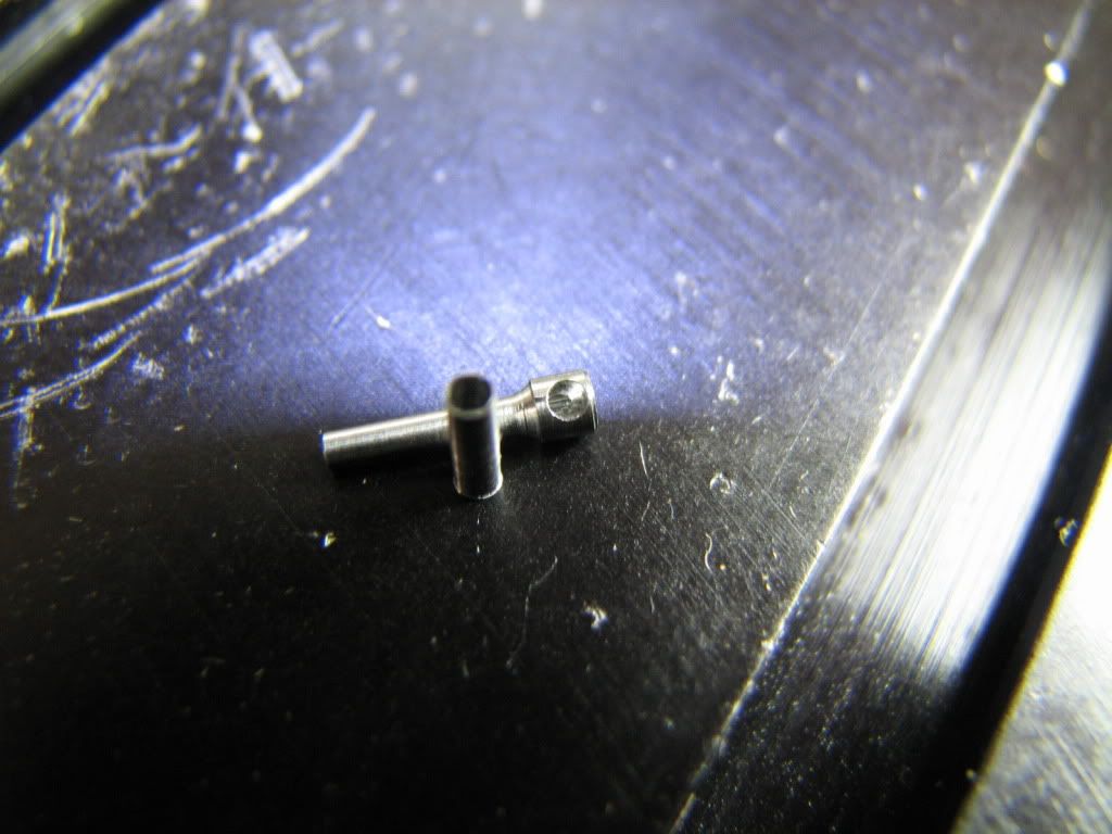
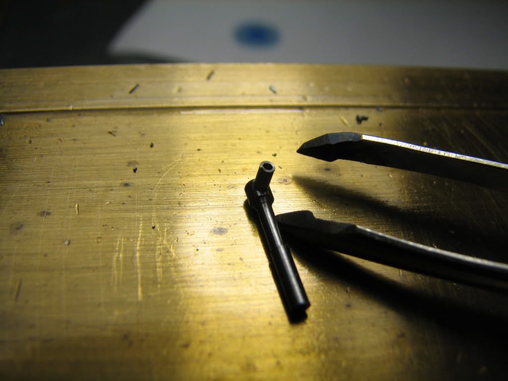
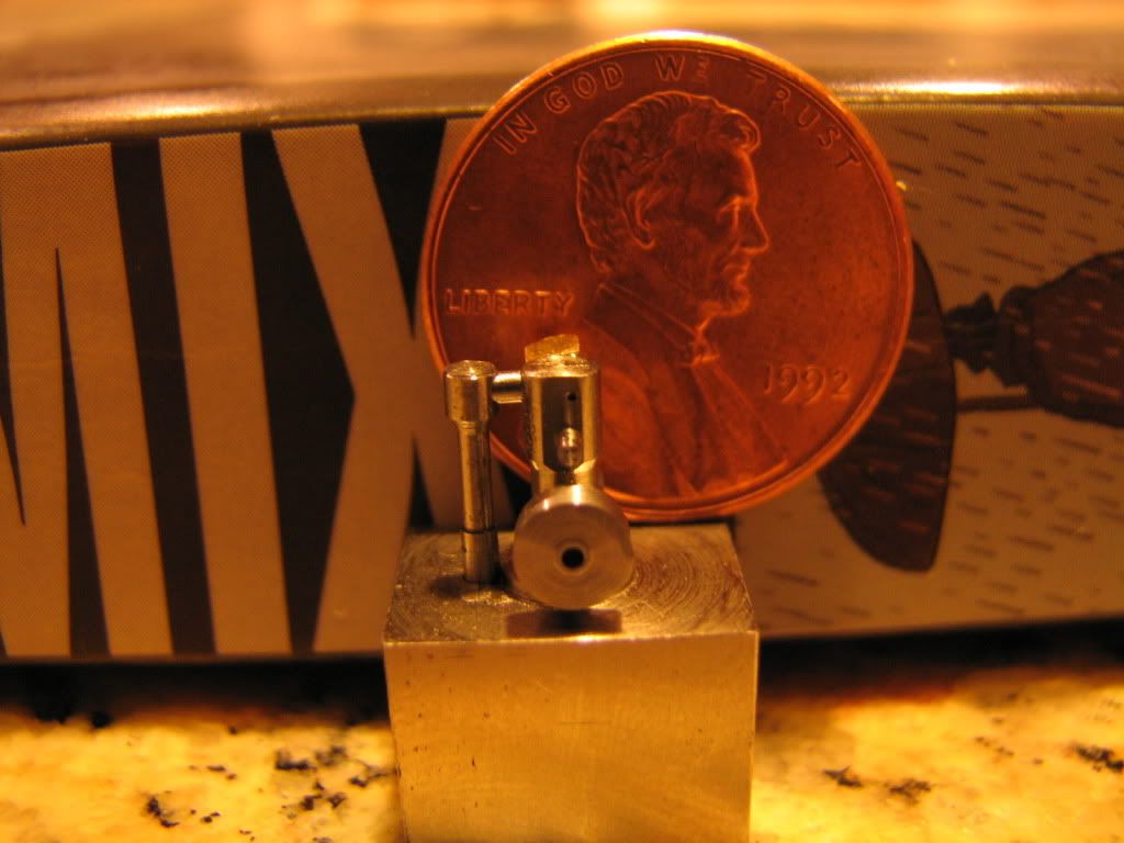
These are 2 parts that will form the ascending airduct (My drill is a tad short, and I had to build the duct up from 2 parts). The part that is laying down is 0.285" long, with a stem of 0.044" diameter. The upright part is the lower portion of the ascending airduct, has an external diameter of 0.0531" and it's upper part has a hole at 0.0445" to receive the other
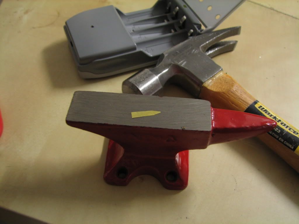
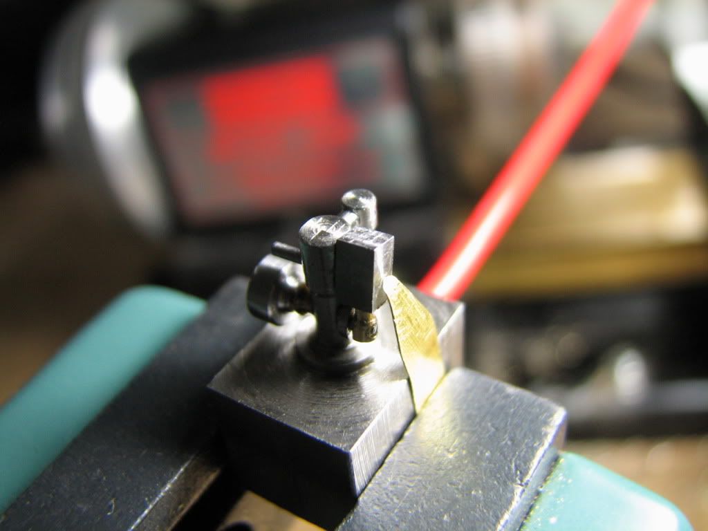
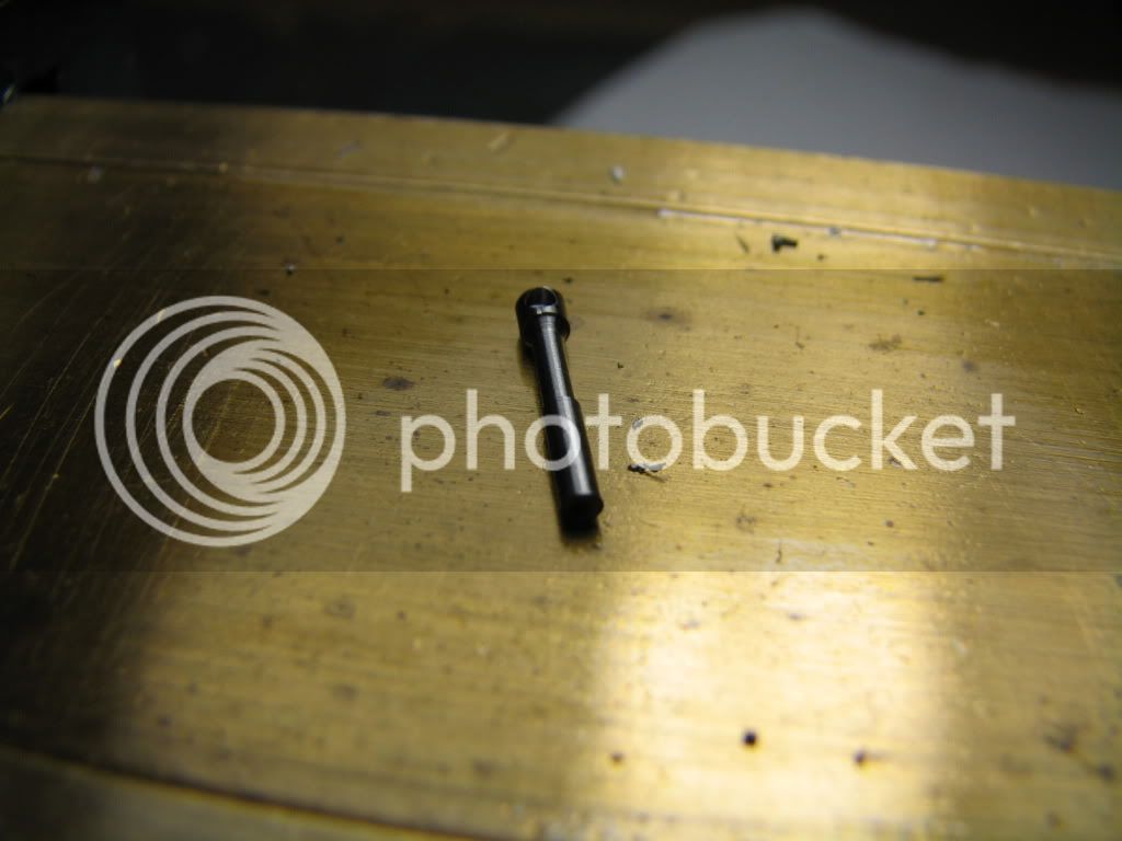
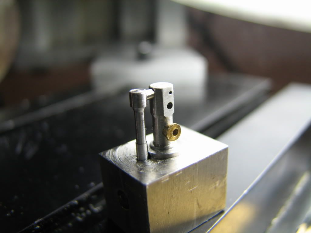
The two parts loctited together
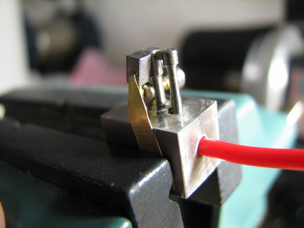
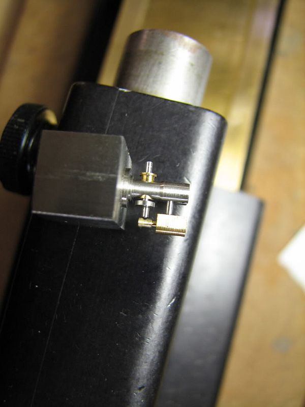
And with the horizontal bridge that will connect to the main column of the engine.
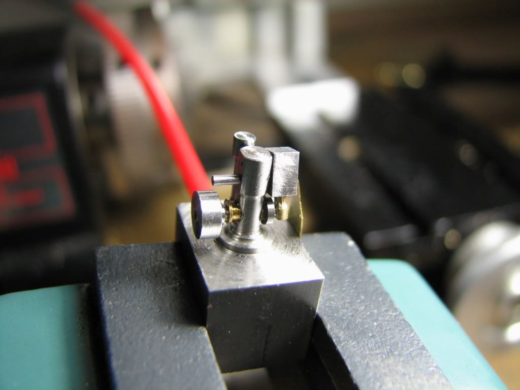
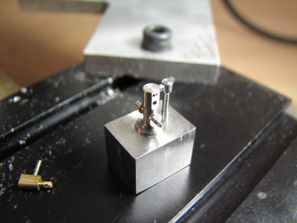
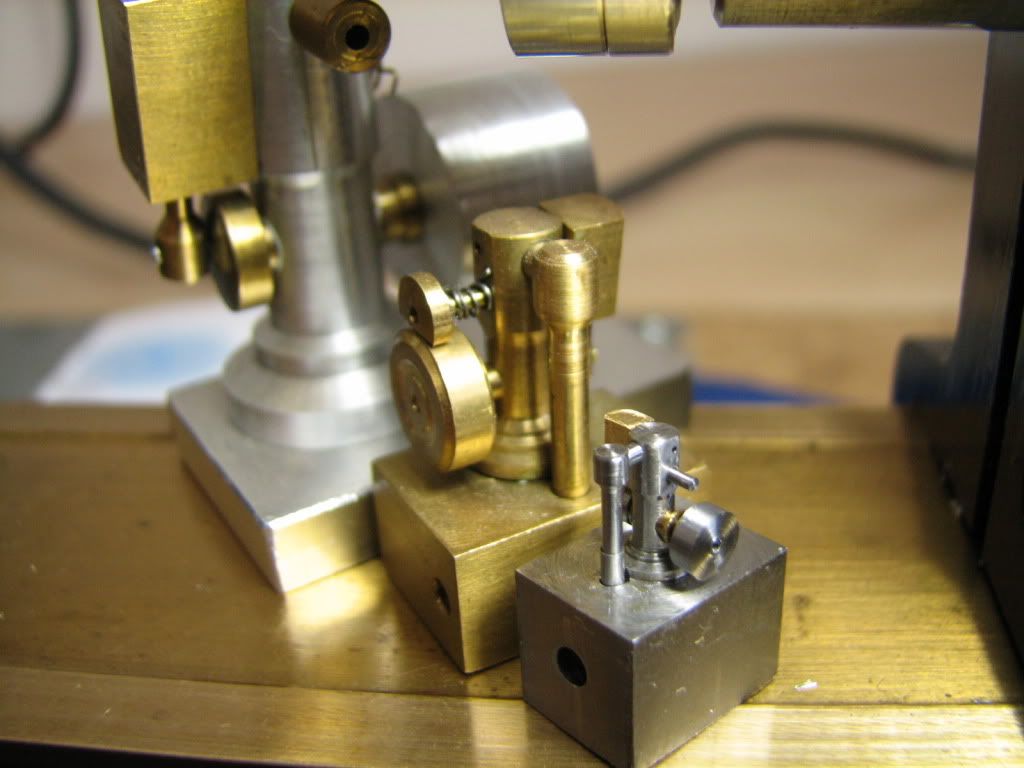
This is how it fits the main column of the engine. If you were following the thread you may remember that my mill has had an extensive 6-7 thousands of backlash which I mistakenly did not account for when drilling the ports and holes, which ended upp 6 thousands off center. To correct the geometry I made an eccentric bushing for the crankshaft - eccentric by 6 thousands. :-*
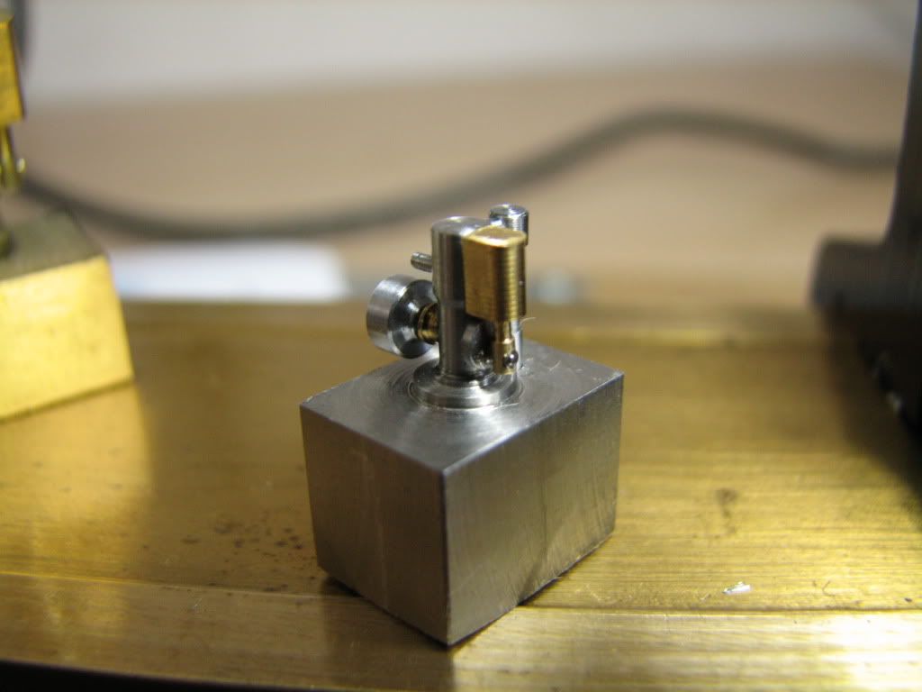
Crankshaft in place, cylinder and piston assortment on the left.
They fit...
Note the long pivot pin -- it is meant to have a tiny spring to hold the cylinder in place... Instead of a spring I'll use another solution (thanks Bogs)...
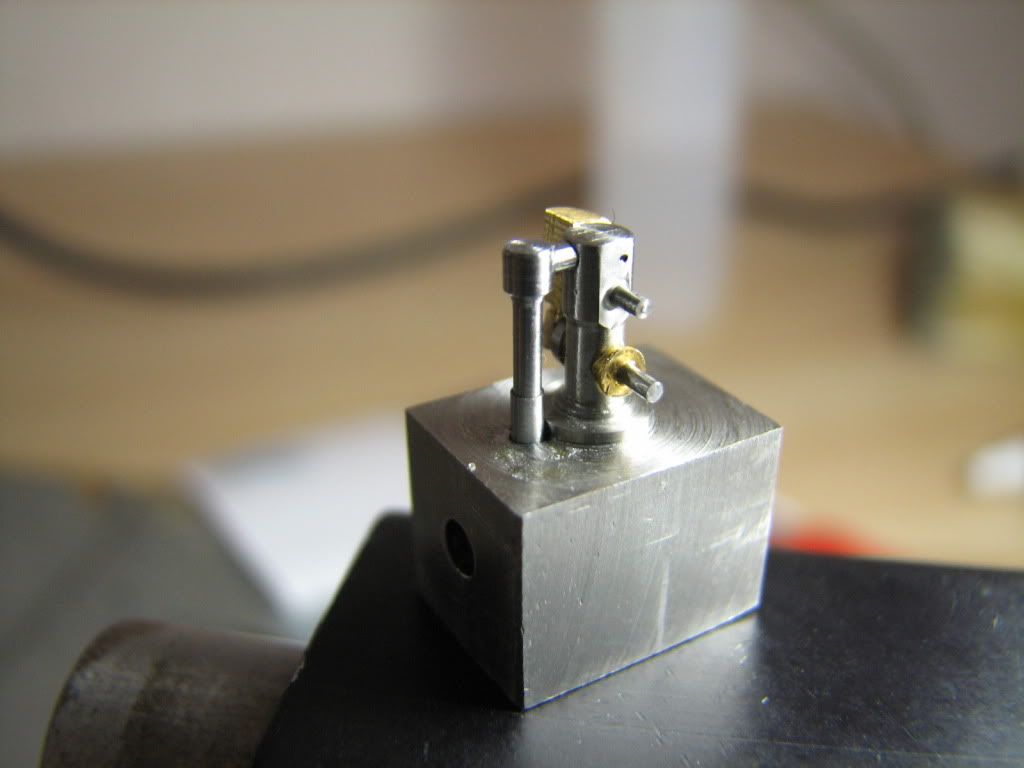
Another view...
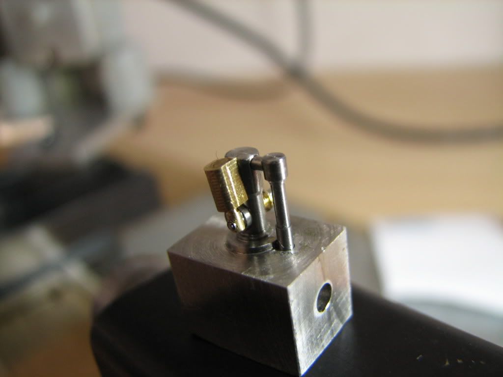
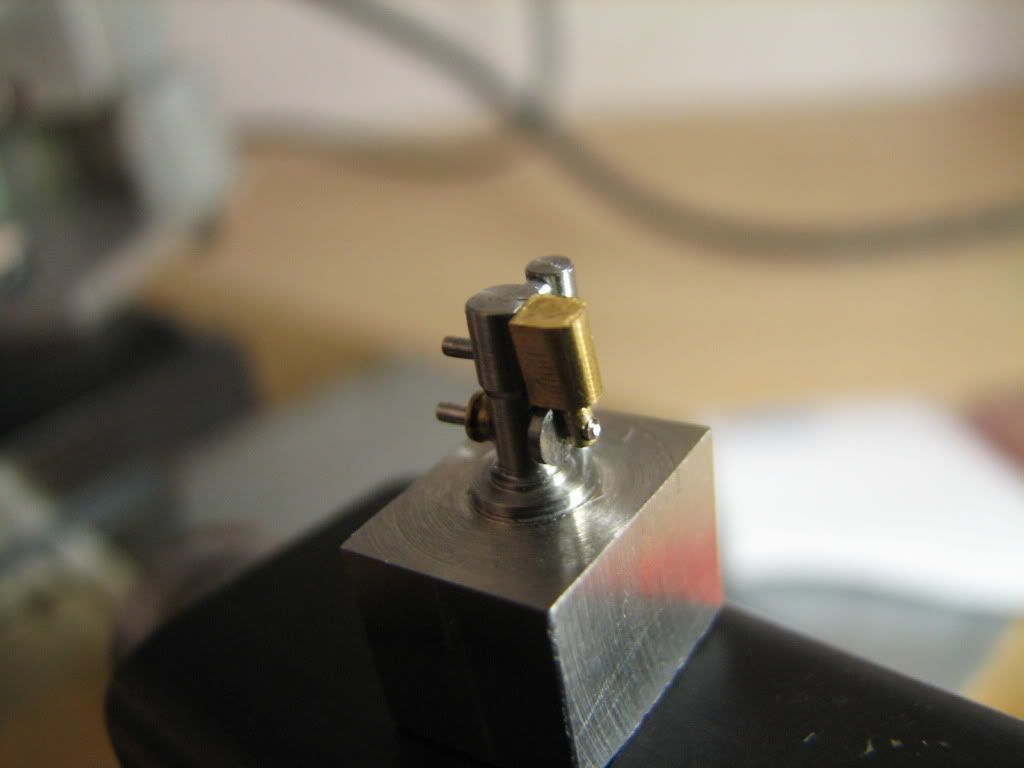
Another view...
With the flywheel...
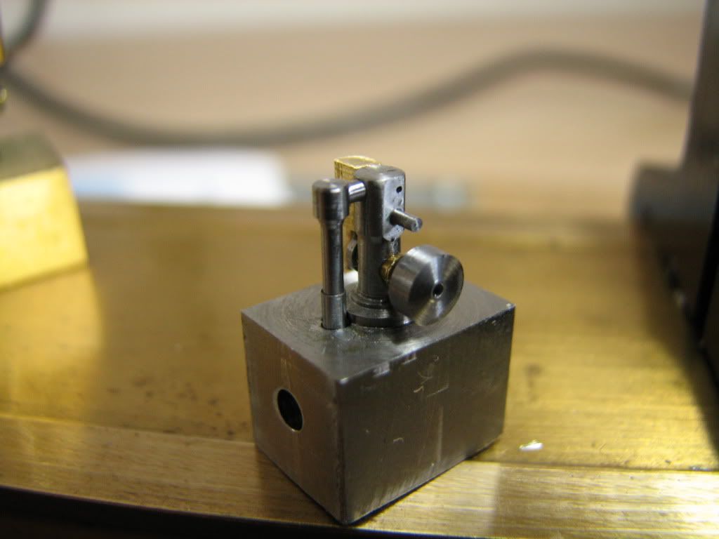
Another angle...
Together with the 1/2 size of Elmer's tiny I made last year...
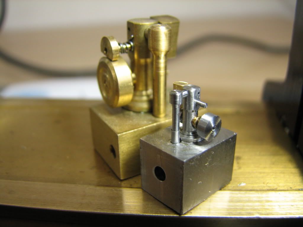
And together with the full size of the tiny...
Next week, perhaps, I'll implement Bogs' solution to replace the string... and test if it runs...
till then take care,
tom in MA
I had to machnine the airducts. Because the engine is so small, I have to supply the air through the base.
These are 2 parts that will form the ascending airduct (My drill is a tad short, and I had to build the duct up from 2 parts). The part that is laying down is 0.285" long, with a stem of 0.044" diameter. The upright part is the lower portion of the ascending airduct, has an external diameter of 0.0531" and it's upper part has a hole at 0.0445" to receive the other
The two parts loctited together
And with the horizontal bridge that will connect to the main column of the engine.
This is how it fits the main column of the engine. If you were following the thread you may remember that my mill has had an extensive 6-7 thousands of backlash which I mistakenly did not account for when drilling the ports and holes, which ended upp 6 thousands off center. To correct the geometry I made an eccentric bushing for the crankshaft - eccentric by 6 thousands. :-*
Crankshaft in place, cylinder and piston assortment on the left.
They fit...
Note the long pivot pin -- it is meant to have a tiny spring to hold the cylinder in place... Instead of a spring I'll use another solution (thanks Bogs)...
Another view...
Another view...
With the flywheel...
Another angle...
Together with the 1/2 size of Elmer's tiny I made last year...
And together with the full size of the tiny...
Next week, perhaps, I'll implement Bogs' solution to replace the string... and test if it runs...
till then take care,
tom in MA
 (but not as nice). Amazing work Tom!