After building my first ever runner (Elmer's Tiny) and my second ever runner (Elmer's Tiny in 1/2 scale)
http://www.homemodelenginemachinist.com/index.php?topic=6231.0
I decided to build Elmer's Tiny in 1/4 scale... So I was in serious need of new tools... Feedback in my first post suggested that the task is not trivial...
BTW, plans are found in this wonderful site... as most of you know") ... go to engine #23...
... go to engine #23...
http://www.john-tom.com/html/ElmersEngines.html
A few weeks back I bothered your graces with my log for the stereomicroscope mount...
http://www.homemodelenginemachinist.com/index.php?topic=6383.0
So now that I got a set of small drills from HF and a set of mini endmills from EBay I decided to start with the column...
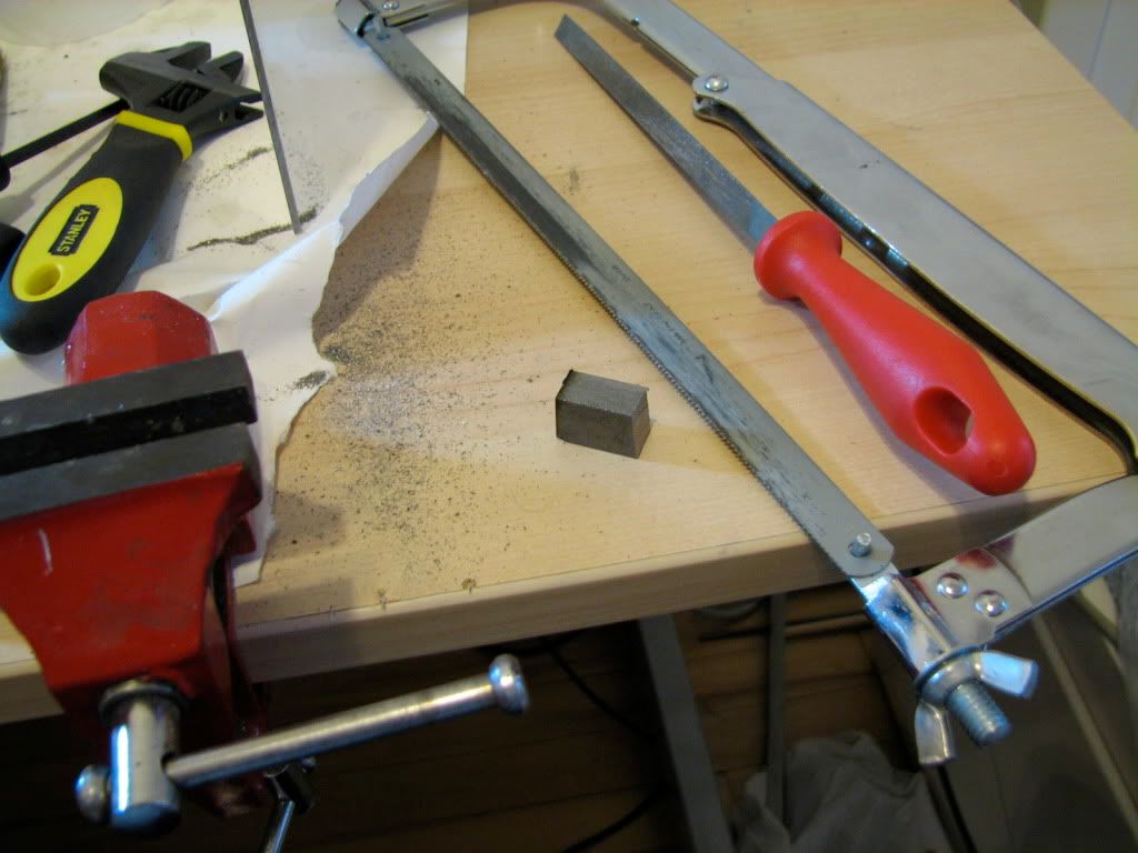
First, hacksaw to part a small piece of steel... Which I then milled to make square surfaces.
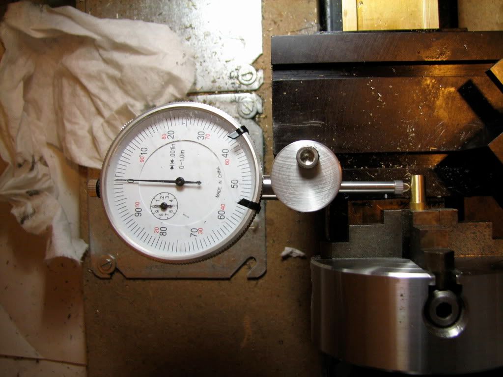
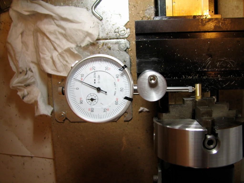
Mill on the floor, lathe on the desk... Mounted on the 4 jaw. This is a Taig 4" chuck that fits my Sherline... It's a bit bulky... I need to get a smaller one... I centered the piece with the indicator, mounted on a home-made base that holds it to the center of the spindle.
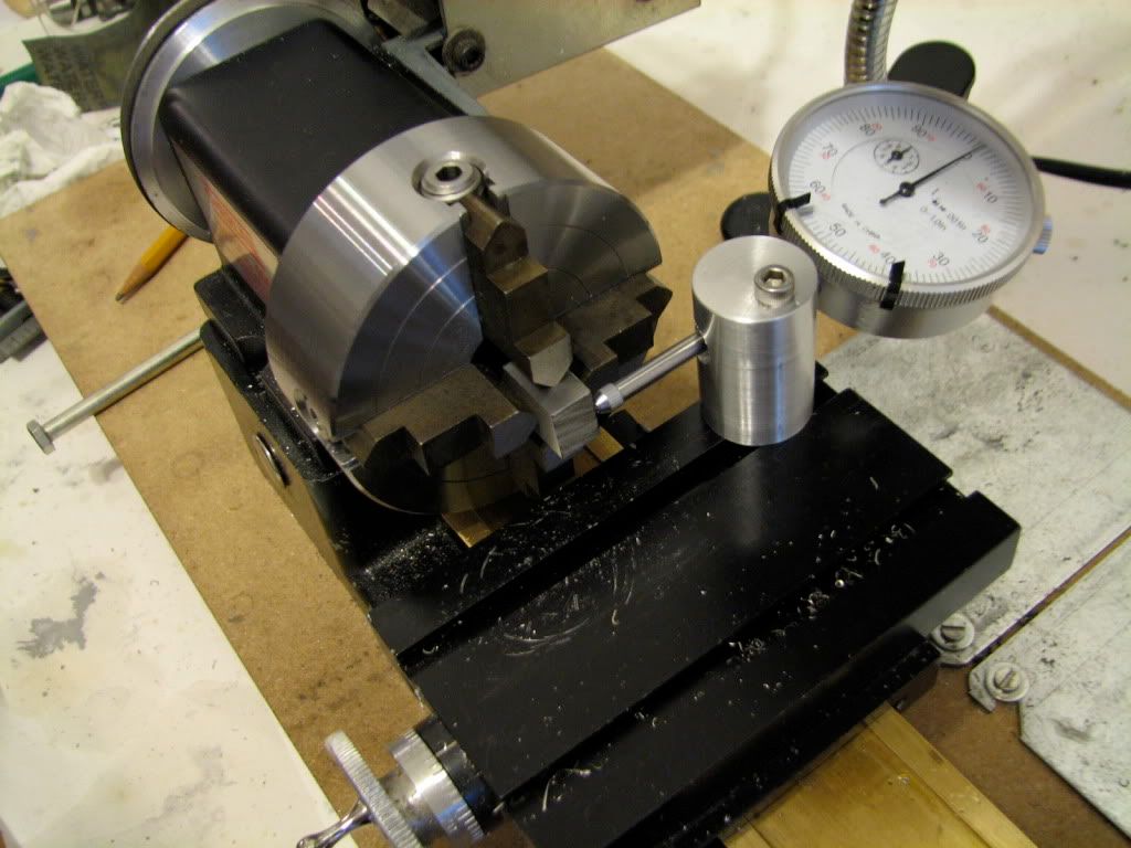
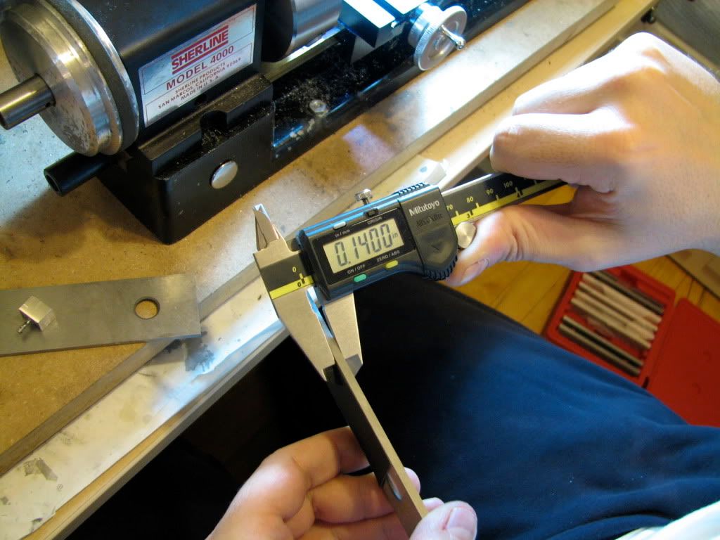
Then I turned the stock down to start forming the column... The diameter at this point is 0.189" - it will be turned down further later.
Lathe on the floor, mill on the desk. Indicating a good reference for the Y axis.
Mounting the piece directly on the mill table. So exciting...
... and so dummkopf... the screw of the mounting gear (step block) gets in the way...
... but also the milling collet is practically sitting in the spindle and the headstock does not go so low... so the whole setup was in vain. Anyhow, milling vise. Here I drill the hole that will accommodate the bushing for the crankshaft (and the crankshaft). I started with a #80 drill (why??? - not shown) and then enlarged with a #67 - shown.
Then drill to size with a 1/16". Note that I do not make everything to scale. First I have no tools, second, I think that the shafts will be too feeble if I make them 1/4 scale... Third I could not care less. ;D ;D ;D. I'm sure Elmer Verbung would approve :hDe:
Then I started drilling the hole for the cylinder pivot thingie (shaft). This is a #80 drill, can you see it going all the way through?. I enjoyed drilling with these small drills... it was completely unnecessary though... I made the final hole a #66. Do not ask why. Because.
Then I milled a small flat where the steam ports would be, and I center-drilled (not shown) the first of the 2 steam ports (not shown). I did not use a jig, as Elmer does. I trig'ed out the location of the holes and did them manually. I aimed to make the holes now that the column has not been turned down to final diameter and is thus more rigid...
I decided that the holes should be #80. The centers of the 2 steam ports (intake/outtake) are in a 0.023" distance... There is not a lot of room for larger diameters... This thing will need some serious air pressure to run.. if it ever runs...
AND THEN THE S**T HIT THE FAN. :fan: BIG TIME th_wtf1 !!! The freaking #80 drill broke in the port. I guess I was too drilling-happy...
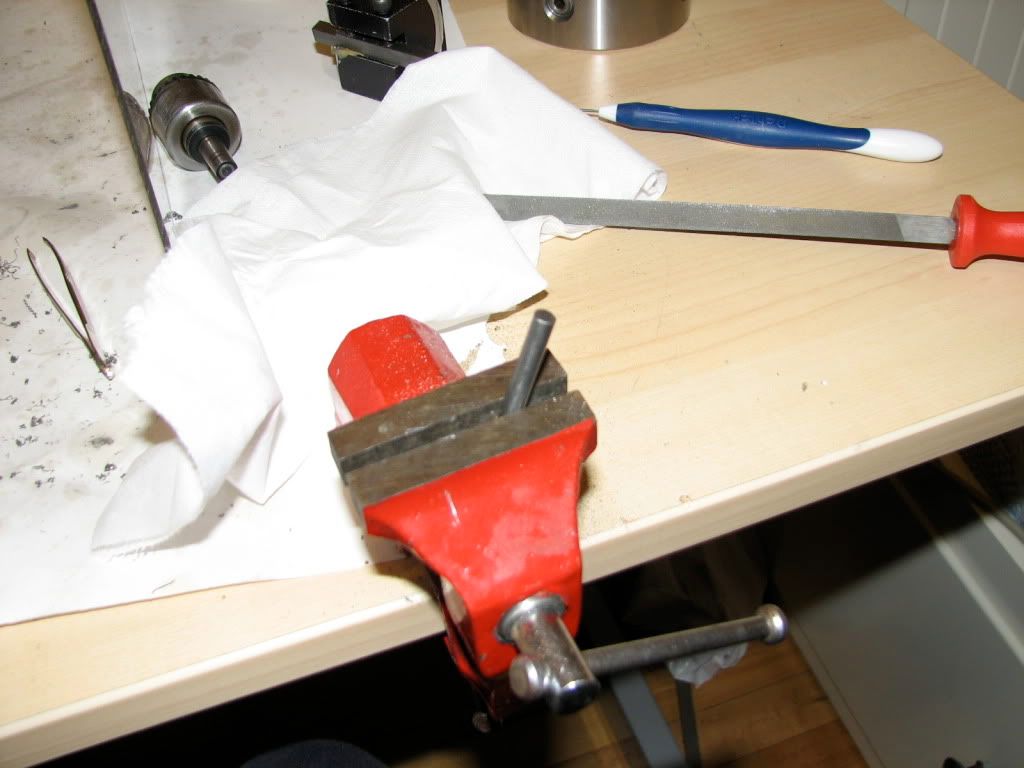
Anyway, tried to salvage the part by... taking the broken drill out. *bang*
You know the routine. Mill on the floor, lathe on the desk.
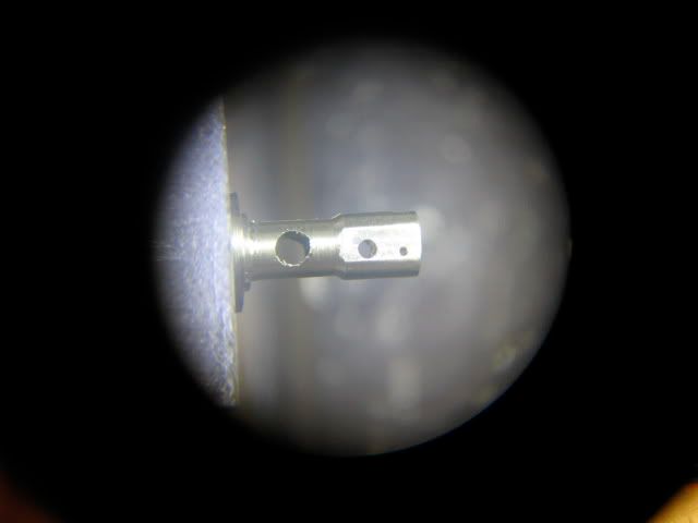
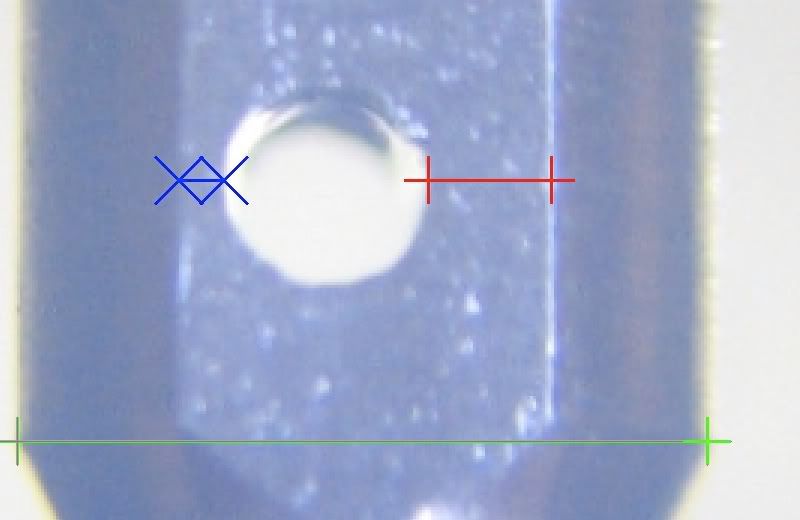
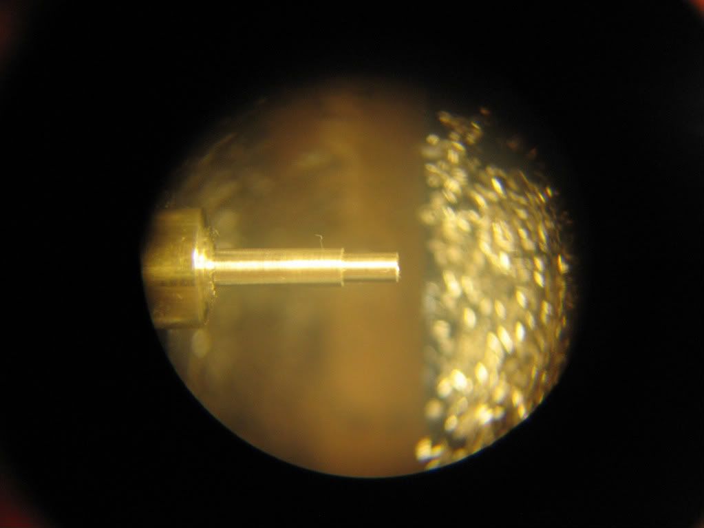
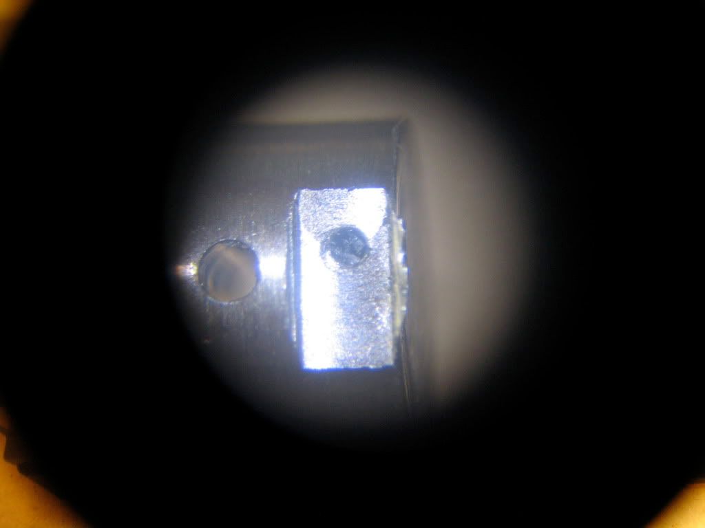
I put the stereomicroscope on. This is an image of the problem.
You can see the #66 hole for the pivot of the cylinder on the left, and the small flat I milled to facilitate drilling of the steam ports. You see the port with the drill broken in there. The photo does not do justice to the microscope image... I could see the little bugger in there... :redface2:
Since the current diameter is 0.189" and the final diameter is 0.109", there is some meat on the column I can turn down... Do i decided to start turning down to get close to the outer part of the broken bit.
and then I started eating away the distal wall of the hole, trying to free the broken bit... At this point I could not get the broken part out with a tweezer or anything I have... But running the lathe at highest RMP, it threw the broken bit out. Sweet :-* . (In the photo, the broken drill is still in there.)
After that I turned down the column to its final diameter (for the column "head") of 0.109" and went on to drill the port holes, and the side hole from which steam will come in.
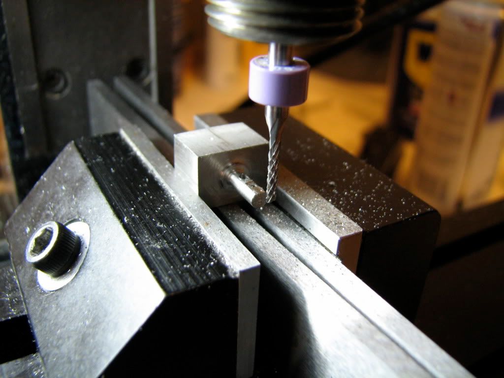
Again, lathe on the floor, mill on the desk. Here I mill the flats on the column. On one of the them (flats) the cylinder will sit.
I do not show how I drilled the steam ports (I did). But after being guided by the force and drilling all the holes and the flats without really seeing wtf i was doing, I decided to inspect...
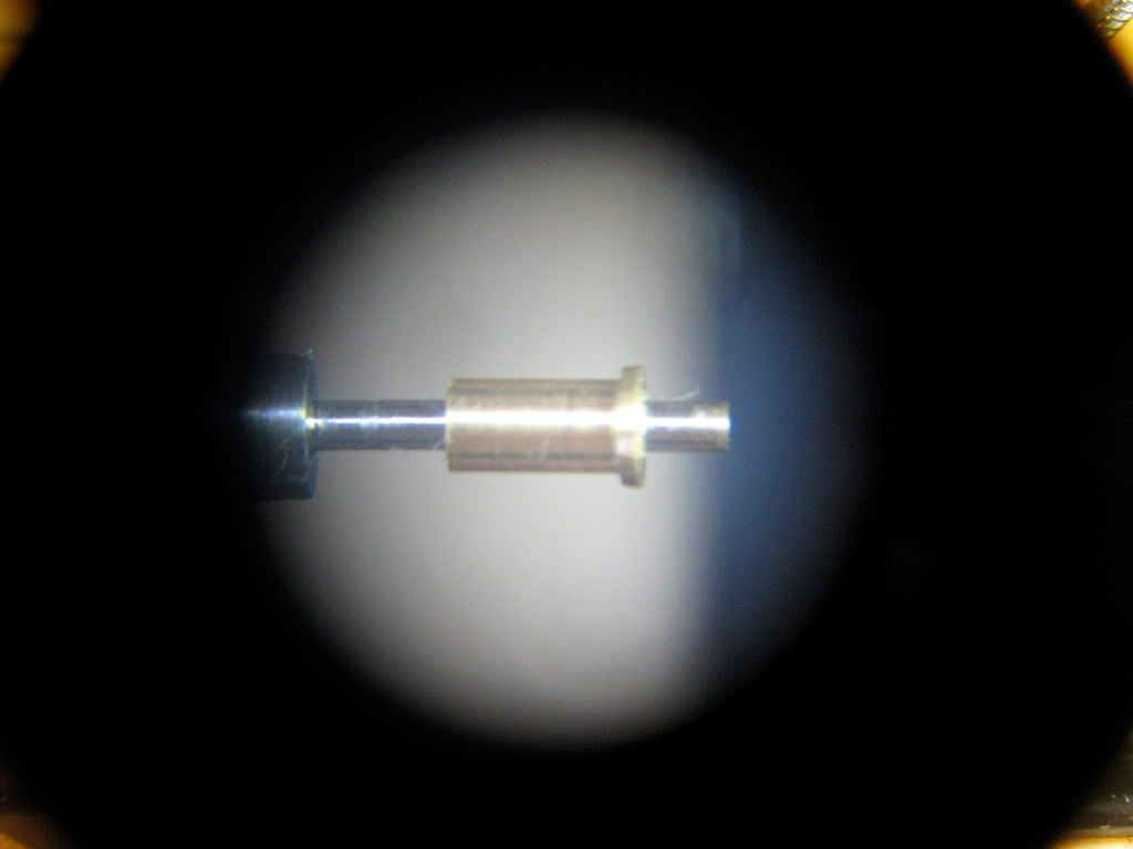
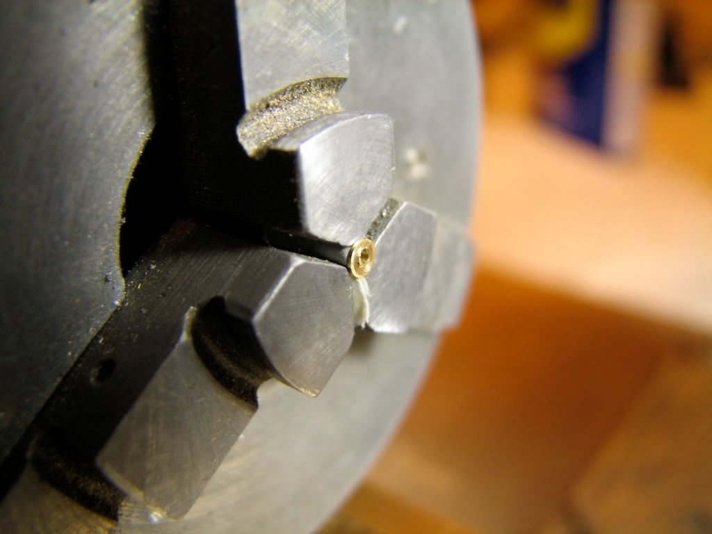
Mill on the floor, lathe on the desk. After mounting and centering on the 4-jaw, a few peeks through the stereomicroscope...
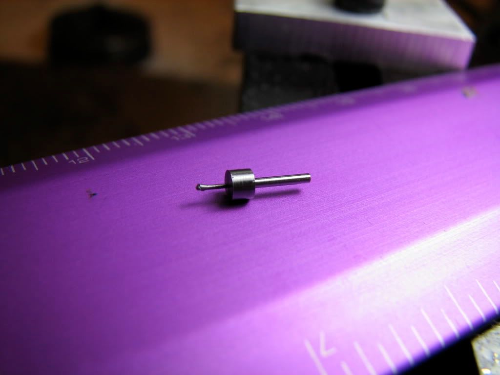
It is a small bugger.
Here is the hole for the bushing/crankshaft.
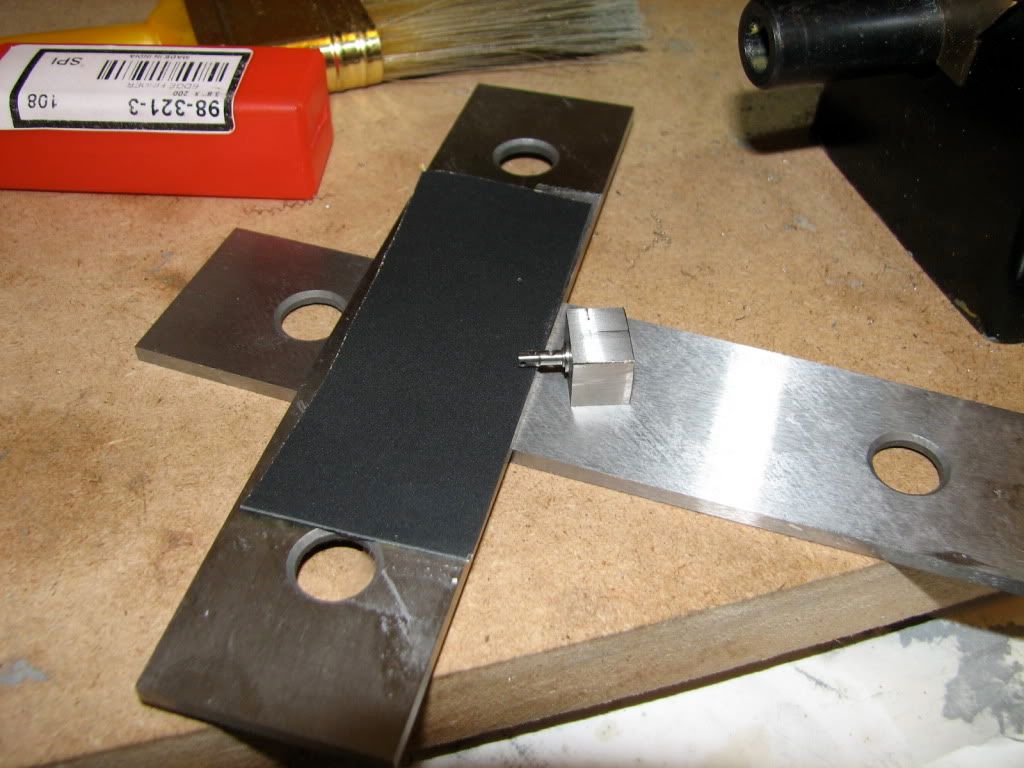
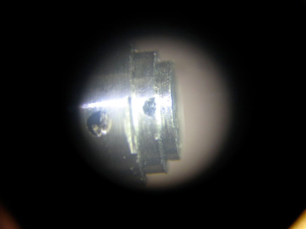
This is the flat from the side of the cylinder. Note that the bigger hole on the left does not sit on the center of the flat... I messed up a tad. Also, the flat is wider on the right and narrower on the left, suggesting that the column was not horizontal when I milled it... OK, I'll fix with fine grit wet dry paper. But LATER. The other two holes are the steam ports. When I center-drilled for the one on top I went a bit down, so there is a chamfer there. Oh well. at least the other one is OK. More or less. For done without really seeing what was done... Enough excuses. Next.
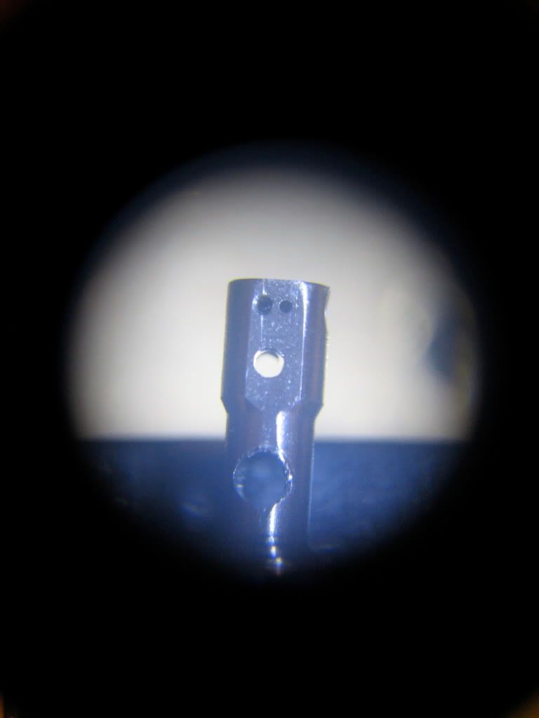
This is the other side, the other flat. Again, the bigger cylinder pivot hole on the left and the outtake steam port on the right. (The other port is a blind hole that meets an ipsilateral steam input side hole.) I know, the flat is not good. It bothers me and I'll fix it. LATER.
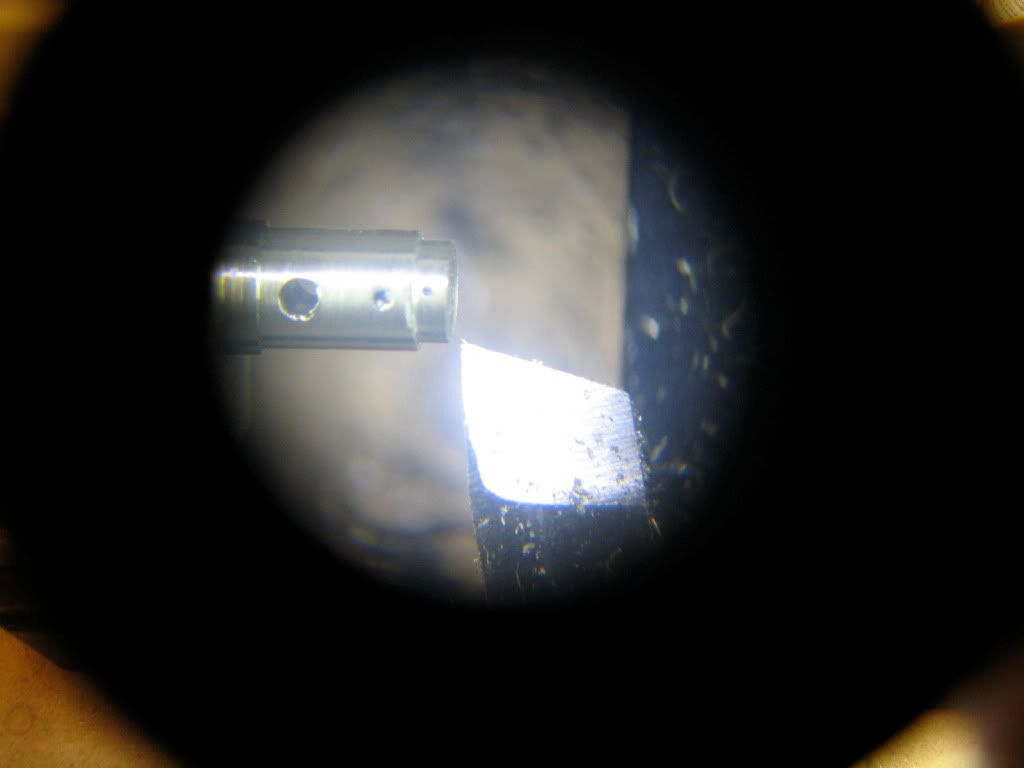
This shows the side hole that meets the (blind hole for the) input port. The input port is barely visible on the flat, top right side of the photograph.
This is how the input port meets the side hole. Bottom right, on the flat you can barely see the outtake port (essentially a through hole).
And this shows where the intake port stops in the bottom of the well of the side hole...
The column is not complete... I have to fix the flats, clear burrs and turn down a small region in the middle of the column a bit more, as per plans... but this will be done next time. Probably in a couple of weekends... I have a friend visiting and he'll need the room where the home shop is...
Any advice on how to correct the flats welcome...
take care
tom
http://www.homemodelenginemachinist.com/index.php?topic=6231.0
I decided to build Elmer's Tiny in 1/4 scale... So I was in serious need of new tools... Feedback in my first post suggested that the task is not trivial...
BTW, plans are found in this wonderful site... as most of you know
... go to engine #23...http://www.john-tom.com/html/ElmersEngines.html
A few weeks back I bothered your graces with my log for the stereomicroscope mount...
http://www.homemodelenginemachinist.com/index.php?topic=6383.0
So now that I got a set of small drills from HF and a set of mini endmills from EBay I decided to start with the column...
First, hacksaw to part a small piece of steel... Which I then milled to make square surfaces.
Mill on the floor, lathe on the desk... Mounted on the 4 jaw. This is a Taig 4" chuck that fits my Sherline... It's a bit bulky... I need to get a smaller one... I centered the piece with the indicator, mounted on a home-made base that holds it to the center of the spindle.
Then I turned the stock down to start forming the column... The diameter at this point is 0.189" - it will be turned down further later.
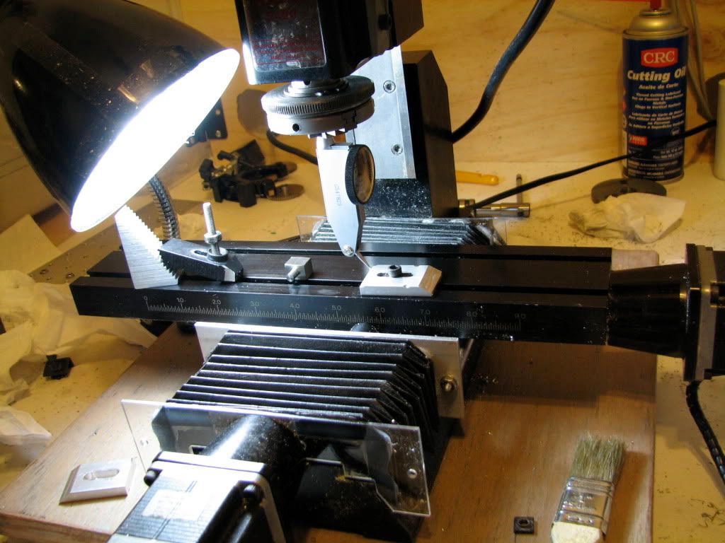
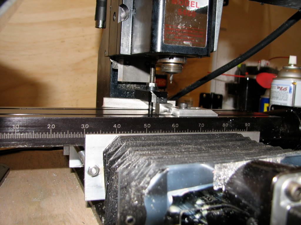
Lathe on the floor, mill on the desk. Indicating a good reference for the Y axis.
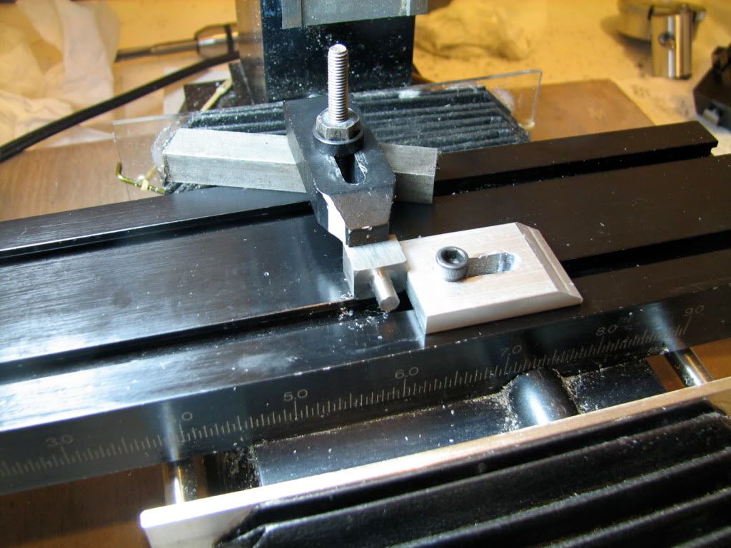
Mounting the piece directly on the mill table. So exciting...
... and so dummkopf... the screw of the mounting gear (step block) gets in the way...
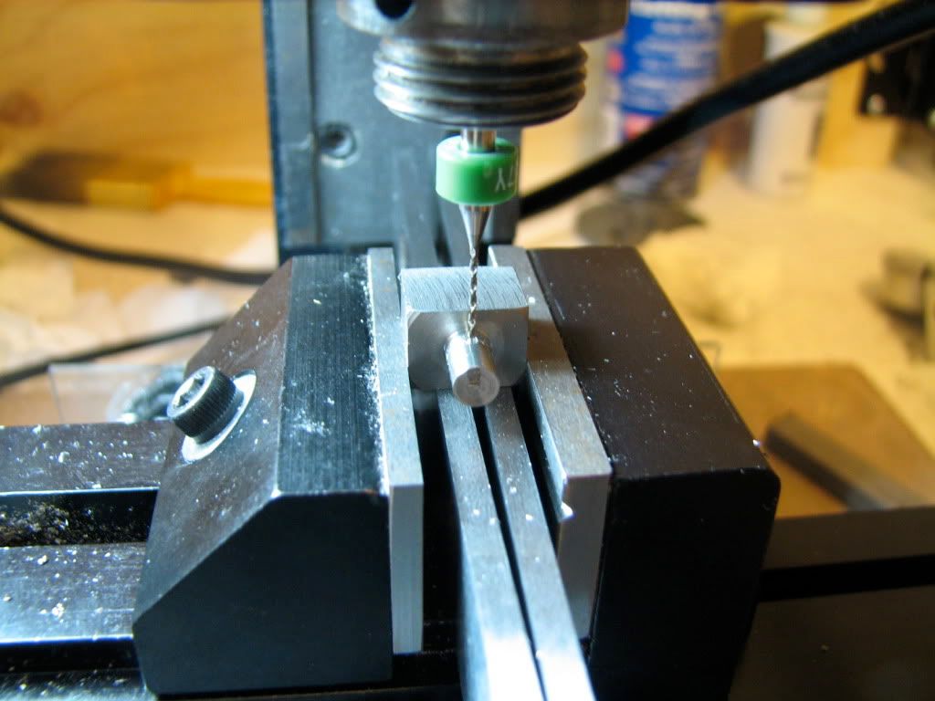
... but also the milling collet is practically sitting in the spindle and the headstock does not go so low... so the whole setup was in vain. Anyhow, milling vise. Here I drill the hole that will accommodate the bushing for the crankshaft (and the crankshaft). I started with a #80 drill (why??? - not shown) and then enlarged with a #67 - shown.
Then drill to size with a 1/16". Note that I do not make everything to scale. First I have no tools, second, I think that the shafts will be too feeble if I make them 1/4 scale... Third I could not care less. ;D ;D ;D. I'm sure Elmer Verbung would approve :hDe:
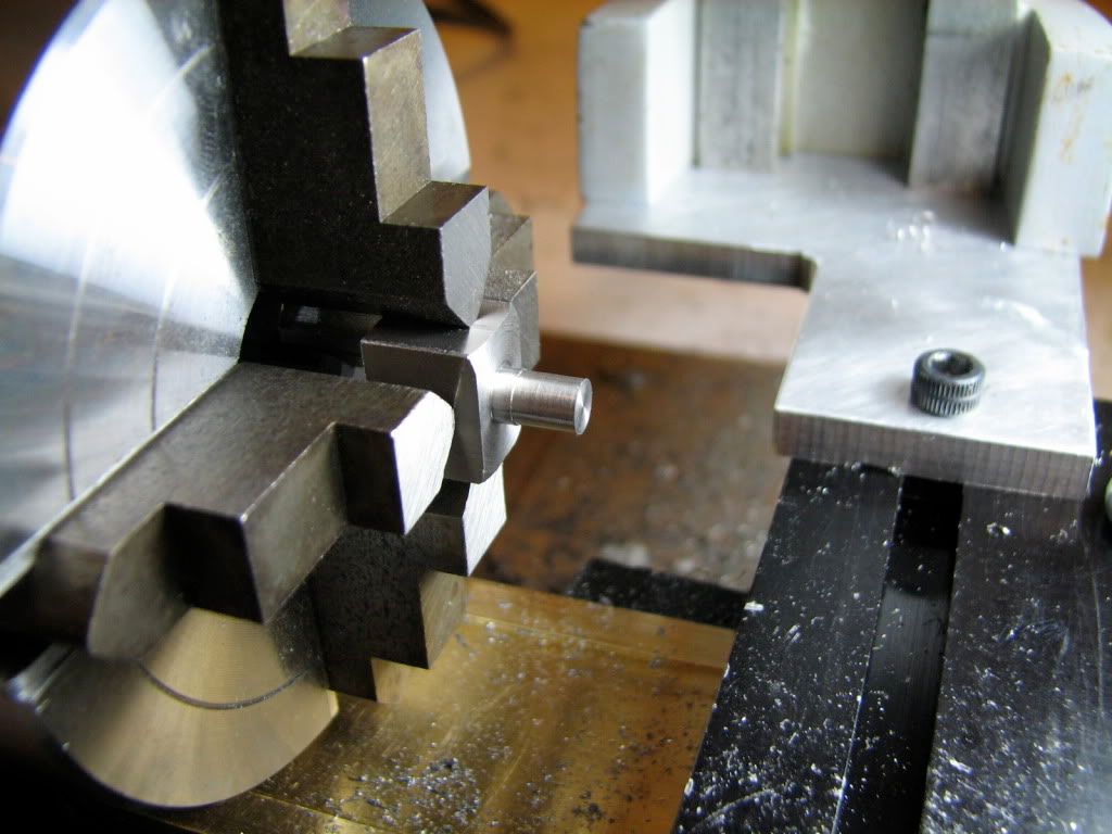
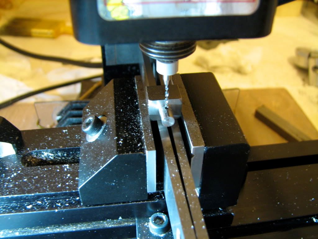
Then I started drilling the hole for the cylinder pivot thingie (shaft). This is a #80 drill, can you see it going all the way through?
. I enjoyed drilling with these small drills... it was completely unnecessary though... I made the final hole a #66. Do not ask why. Because.
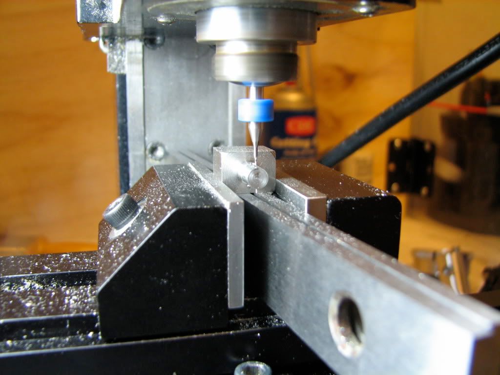
Then I milled a small flat where the steam ports would be, and I center-drilled (not shown) the first of the 2 steam ports (not shown). I did not use a jig, as Elmer does. I trig'ed out the location of the holes and did them manually. I aimed to make the holes now that the column has not been turned down to final diameter and is thus more rigid...
I decided that the holes should be #80. The centers of the 2 steam ports (intake/outtake) are in a 0.023" distance... There is not a lot of room for larger diameters... This thing will need some serious air pressure to run.. if it ever runs...
AND THEN THE S**T HIT THE FAN. :fan: BIG TIME th_wtf1 !!! The freaking #80 drill broke in the port. I guess I was too drilling-happy...
Anyway, tried to salvage the part by... taking the broken drill out. *bang*
You know the routine. Mill on the floor, lathe on the desk.
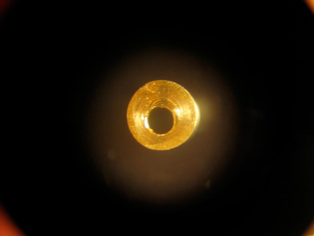
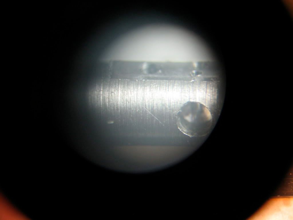
I put the stereomicroscope on. This is an image of the problem.
You can see the #66 hole for the pivot of the cylinder on the left, and the small flat I milled to facilitate drilling of the steam ports. You see the port with the drill broken in there. The photo does not do justice to the microscope image... I could see the little bugger in there... :redface2:
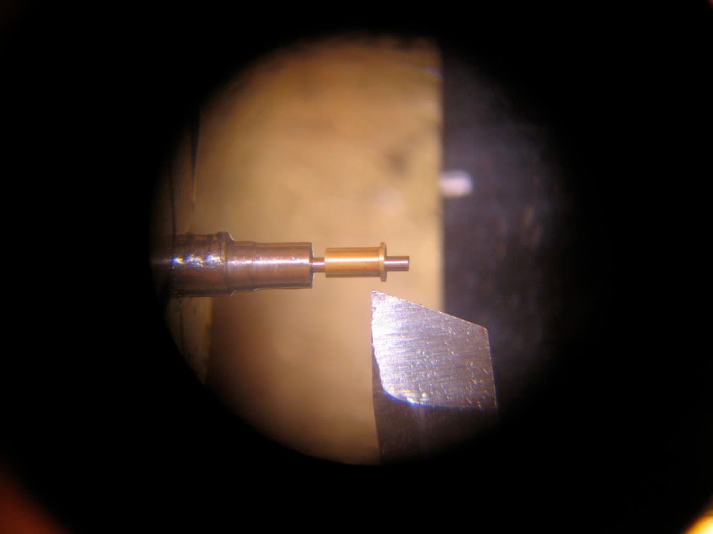
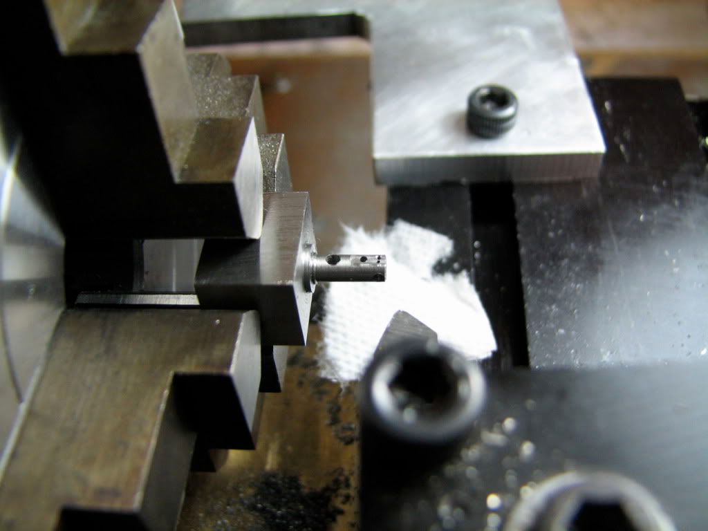
Since the current diameter is 0.189" and the final diameter is 0.109", there is some meat on the column I can turn down... Do i decided to start turning down to get close to the outer part of the broken bit.
and then I started eating away the distal wall of the hole, trying to free the broken bit... At this point I could not get the broken part out with a tweezer or anything I have... But running the lathe at highest RMP, it threw the broken bit out. Sweet :-* . (In the photo, the broken drill is still in there.)
After that I turned down the column to its final diameter (for the column "head") of 0.109" and went on to drill the port holes, and the side hole from which steam will come in.
Again, lathe on the floor, mill on the desk. Here I mill the flats on the column. On one of the them (flats) the cylinder will sit.
I do not show how I drilled the steam ports (I did). But after being guided by the force and drilling all the holes and the flats without really seeing wtf i was doing, I decided to inspect...
Mill on the floor, lathe on the desk. After mounting and centering on the 4-jaw, a few peeks through the stereomicroscope...
It is a small bugger.
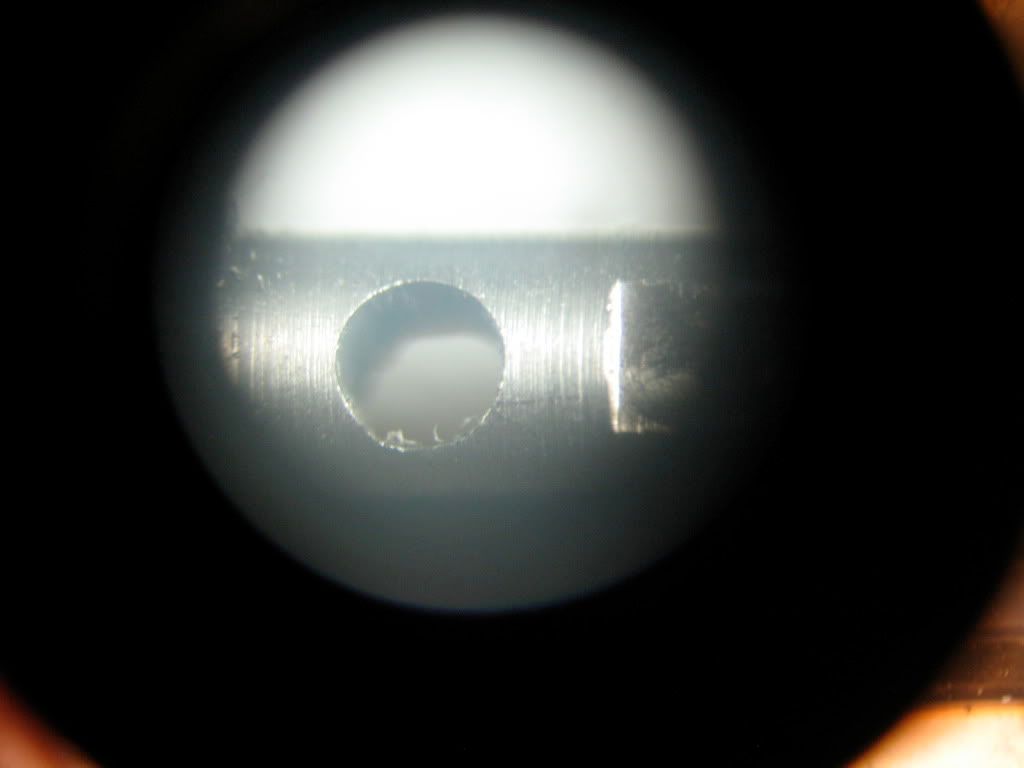
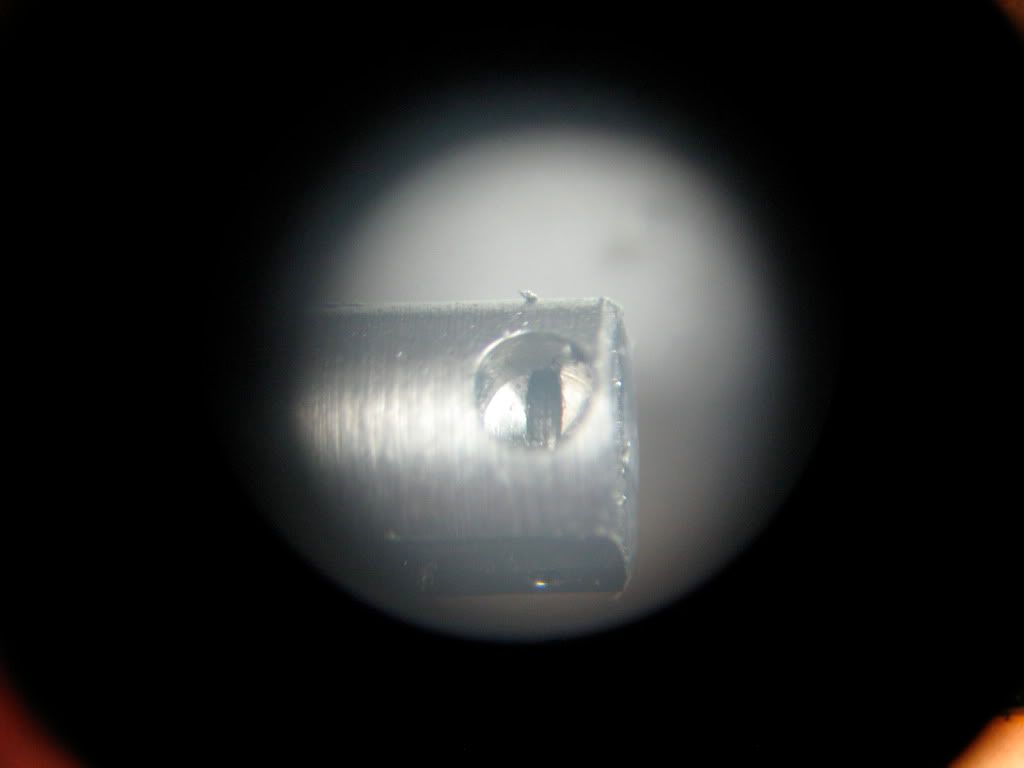
Here is the hole for the bushing/crankshaft.
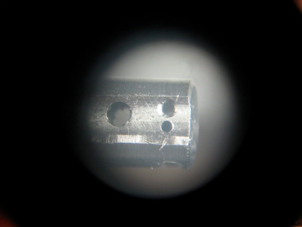
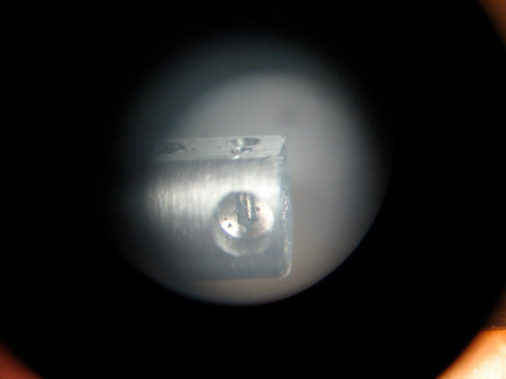
This is the flat from the side of the cylinder. Note that the bigger hole on the left does not sit on the center of the flat... I messed up a tad. Also, the flat is wider on the right and narrower on the left, suggesting that the column was not horizontal when I milled it... OK, I'll fix with fine grit wet dry paper. But LATER. The other two holes are the steam ports. When I center-drilled for the one on top I went a bit down, so there is a chamfer there. Oh well. at least the other one is OK. More or less. For done without really seeing what was done... Enough excuses. Next.
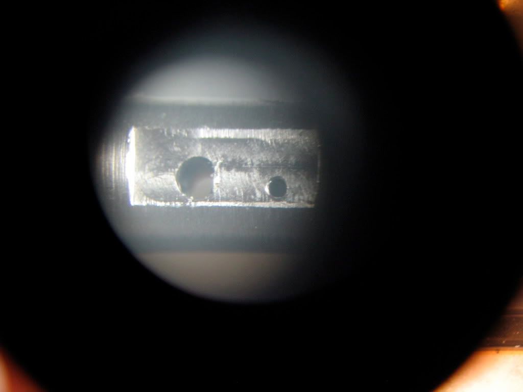
This is the other side, the other flat. Again, the bigger cylinder pivot hole on the left and the outtake steam port on the right. (The other port is a blind hole that meets an ipsilateral steam input side hole.) I know, the flat is not good. It bothers me and I'll fix it. LATER.
This shows the side hole that meets the (blind hole for the) input port. The input port is barely visible on the flat, top right side of the photograph.
This is how the input port meets the side hole. Bottom right, on the flat you can barely see the outtake port (essentially a through hole).
And this shows where the intake port stops in the bottom of the well of the side hole...
The column is not complete... I have to fix the flats, clear burrs and turn down a small region in the middle of the column a bit more, as per plans... but this will be done next time. Probably in a couple of weekends... I have a friend visiting and he'll need the room where the home shop is...
Any advice on how to correct the flats welcome...
take care
tom