
You are using an out of date browser. It may not display this or other websites correctly.
You should upgrade or use an alternative browser.
You should upgrade or use an alternative browser.
Elmer's Tiny in 1/4 scale.
- Thread starter ttrikalin
- Start date


Help Support Home Model Engine Machinist Forum:
This site may earn a commission from merchant affiliate
links, including eBay, Amazon, and others.
hammers-n-nails said:while were talking about micro-steam i found this a while back http://steamtraction.farmcollector.com/Steam-Engines/Smallest-Steam-Engine-in-the-WORLD.aspx how will the overall size of yours compare?
Hammers-n-nails,
The simple engine in this build cannot rival the very complex one in the link you posted. The link said the other one has 150 parts made of silver and gold... mine has approximately 10 (I turn some from solid to simplify things and gain strength -- as I hope it'll run)...
But in terms of sizes, and excluding the base, I have a bigger quarter.
 You can see a bit of my other build f Tiny on the right, in 1/2 scale...
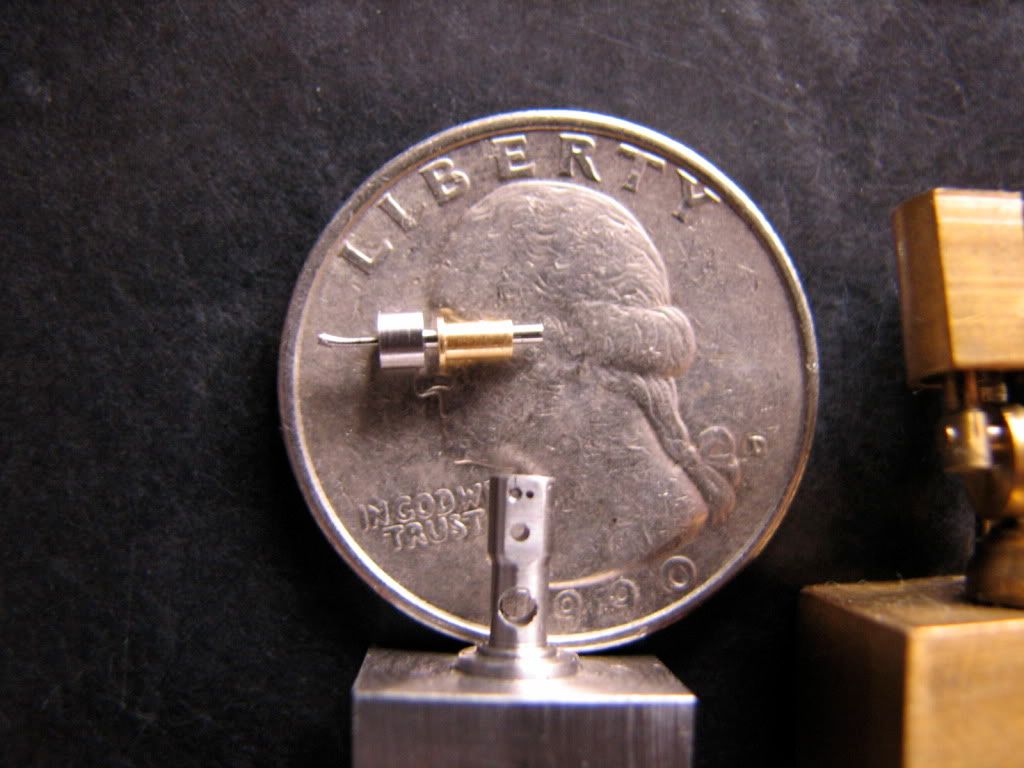
Google Jerry Kieffer to see top notch micromachining. He is finishing a fully functional early model Harley Davidson bike in 1/6 scale, with everything scaled down (to the bolt) -- it will have a functional odometer!!! The engine has been finished and it runs!!!
zeeprogrammer
Well-Known Member
- Joined
- Mar 14, 2009
- Messages
- 3,362
- Reaction score
- 13
Good grief that is small.
I'll be you have a fear of sneezing.
Very nice work.
I'll be you have a fear of sneezing.
Very nice work.
Russel said:Do you have a pin vise?
Many pin vises are designed to be mounted in a chuck. Also, and your mileage may vary, rather than facing the bur off of your offset bushing I would have put the part in a pin vise and honed it with an oilstone or maybe 1000 grit wet or dry sand paper and some thin oil.
I did not have a pin vise but I bought one today. This is a great little tool and so cheap... I'll make a small adapter so that I can mount it on the lathe (MT1 holder with/out a drawbar). Thanks for the pointer, Russ...
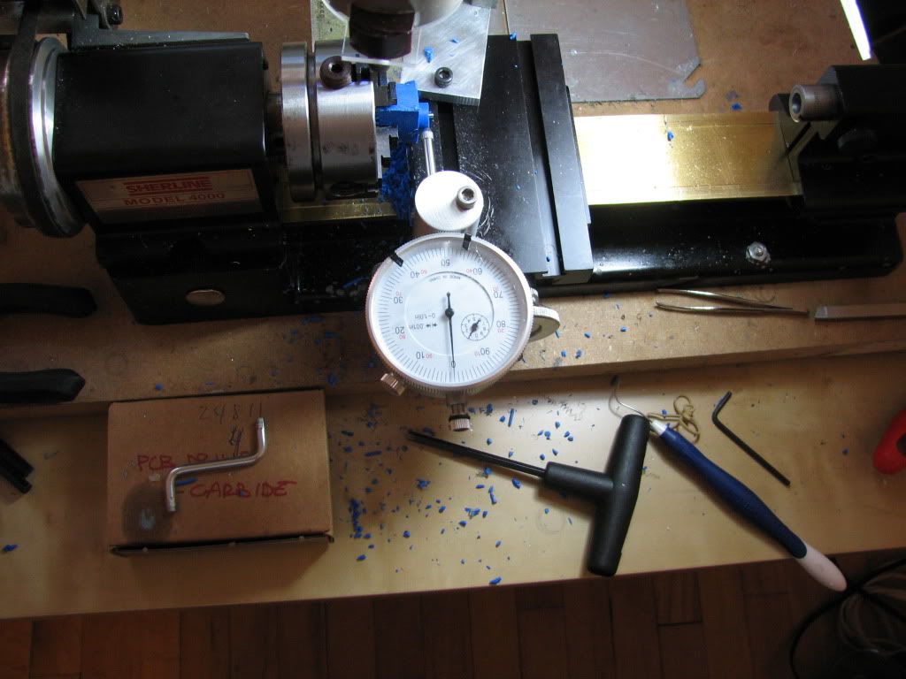
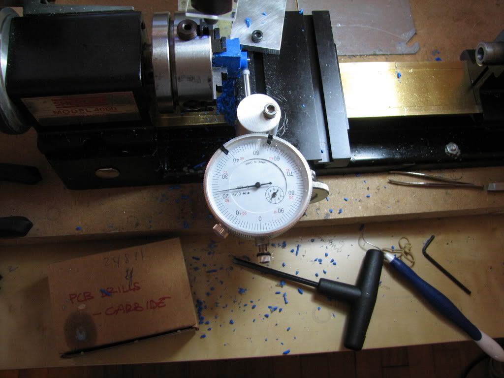
Today was mill tramming day.
Chief Webmentor Jerry G wanted all class members with a mill to learn to tram it correctly... I was delayed in this homework -- so I had to do it today.
Because it is the first time I do it correctly (I think) I made a documentary which I'll upload in the Tips and Tricks section. I'm sure most of you know how to do it, but for me it was a whole morning...
Take care,
tom
Chief Webmentor Jerry G wanted all class members with a mill to learn to tram it correctly... I was delayed in this homework
-- so I had to do it today. Because it is the first time I do it correctly (I think) I made a documentary which I'll upload in the Tips and Tricks section. I'm sure most of you know how to do it, but for me it was a whole morning...
Take care,
tom
Glad to see you're still going with the blow-by-blow on your build, Tom. Little setbacks can be discouraging, but you seem to have it under control!
I forgot who it was that had the brass bed Sherline. It's you!
Nice one.
Dean
I forgot who it was that had the brass bed Sherline. It's you!
Nice one.
Dean
I'm getting pretty tempted to make a couple of standard tiny's for peoples christmas presents - however, I tried this last year and didn't quite get 1 finished! That was designing my own engine though. The tiny looks pretty simple as there are so few components, I guess keeping the tolerances to let it run is the hard bit!
Tom, how was it doing the 1/2 scale one? Don't think I'd cope with stuff that small! Did you do a build log on that or can we have some more pics?
Thanks,
Nick
Tom, how was it doing the 1/2 scale one? Don't think I'd cope with stuff that small! Did you do a build log on that or can we have some more pics?
Thanks,
Nick
NickG said:I'm getting pretty tempted to make a couple of standard tiny's for peoples christmas presents - however, I tried this last year and didn't quite get 1 finished! That was designing my own engine though. The tiny looks pretty simple as there are so few components, I guess keeping the tolerances to let it run is the hard bit!
Tom, how was it doing the 1/2 scale one? Don't think I'd cope with stuff that small! Did you do a build log on that or can we have some more pics?
Thanks,
Nick
That is a neat idea.
Unfortunately I do not have any pics from the build of the 1/2 scale -- I made it before joining this family... It was quite a bit of work for me, as it was my second ever engine. But my 30 year old mildly myopic eyes did not need the microscope for that -- OK was pushing it a bit. I could post figures of the 1/2 as it is now if it helps...
Bob [nickname 90LX_Notch] has built a beautiful 1/2 scale -- shown in his avatar next to his 1/1 scale -- he may have pics of the build...
Bob are you around? Or are you playing with your baby daughter all day? (who can blame you?
)take care,
tom
- Joined
- Dec 28, 2008
- Messages
- 548
- Reaction score
- 4
Nick: My first engine was your design.
Here's the link to the Tiny 1/2 scale build:
http://www.homemodelenginemachinist.com/index.php?topic=4524.0
Tom: Thanks for the compliment. My daughter is keeping us busy, but work is keeping me even more. I just finished a 70+ hour week. I'm starting to get the desire to pick back up on my 1/4 scale build, but as you know you, at this scale it takes a lot of focus and I'm just too tired. I briefly tried spinning mine in the lathe to get the bit out but it didn't work. I'll have to try to debur it and give it another shot. Keep up the good work. You're getting there with yours. Cripes, I started mine in June and you'll be done ahead of me.
Bob
Oh yes, of course Bob, I remember you starting the Tiny after you made my simple engine, didn't realise you'd done a 1/2 scale aswell! Nice 1, they look excellent. I will have to read your build log, the wife is nagging though! I don't think I'd wake up all the following week if I'd done 70 hours! :bow:
Nick
Nick
Almost June 2010. Almost good weather outside the half-opened window in our little apartment near the northern end of the orange line. Almost scrapped the almost finished crankshaft from near 6 months ago...
I'm trying to turn the crankshaft for the 1/4 scale version of Elmer's Tiny from the solid... The modified plans with the scaled down version are in pdf file format here (link in the 2nd line of the narrative):
http://web.me.com/ttrikalin/Machining/Elmers_tiny_1_4_(a).html
This is the half-finished crankshaft from last November... I intend to turn the crankpin by holding from the shaft (0.032" diameter -- beefed up, not to scale) by off-setting by 0.023"
I decided to mount a piece of delrin in the 4-jaw, and open up a hole that snuggly fits the half-finished crankshaft... like a home-made collet... (seriously - delrin? *bang* )
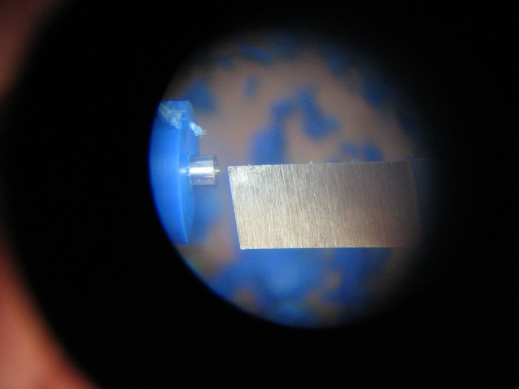
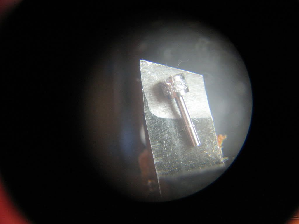
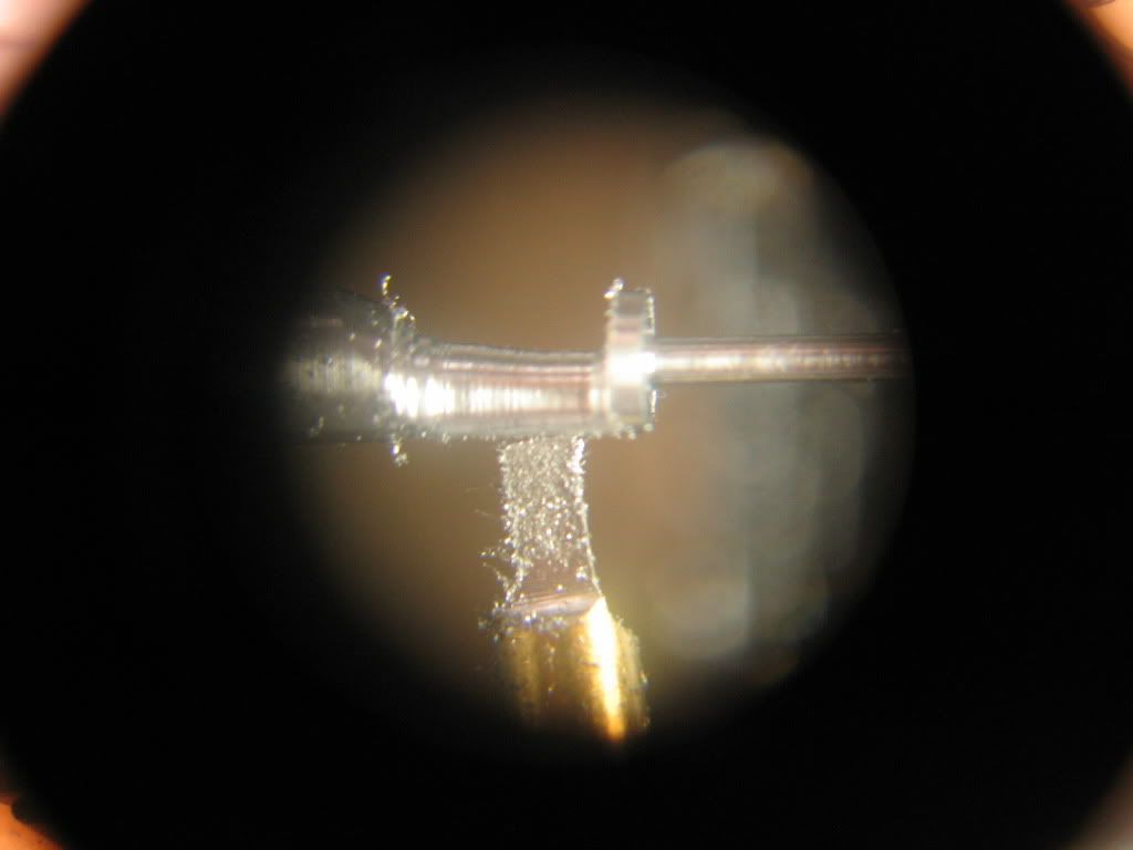
Heres a peek through the stereomicroscope... It is a snug fit... the shafts diameter is a few tenths of a thousand larger...
I will turn the crankpin by offsetting by 0.023. Therefore I turned a reference surface, concentric to the initial hole that holds the crankshaft-to-be. This will help me indicate the offset.
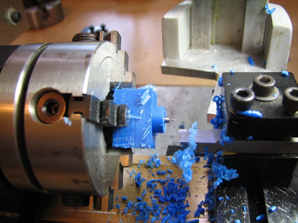
A small dab of silicone to secure the connection... you may be able to see it spill out where the derlin and the crankshaft meet...
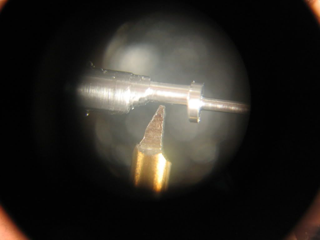
Next step, offset the crankshaft by 0.023 to turn the crankpin. Start at 0, indicating on the reference surface I turned earlier...
and finish at 0.023"...
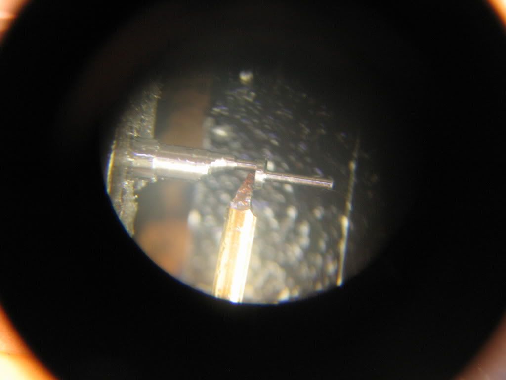
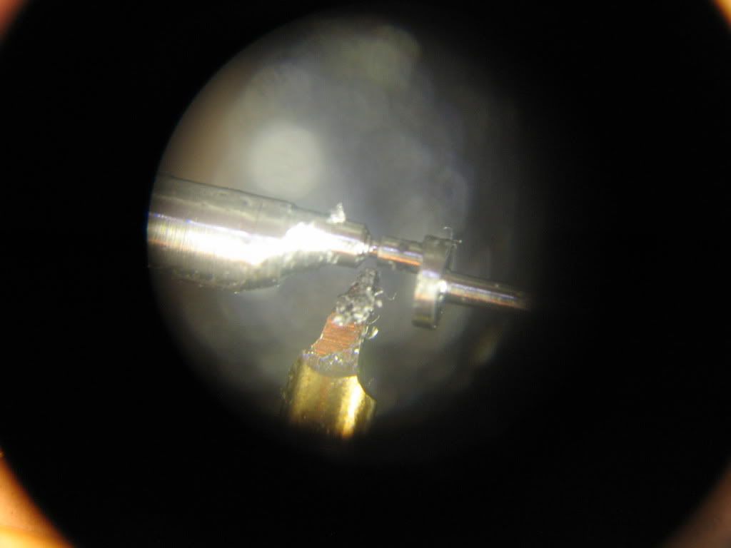
Using derlin was a stupid idea... the connection is not strong enough, and the tool digs in and practically ruins the part... The photo says it all... another difficulty is that with such small parts the machine is relatively huge and there is little sensory feedback while you turn the dials... So i did more damage to the part than needed... but it is salvageable I think...
See the ugly turning job below... from within the stereomicroscope...
Any pointers welcome...
Oh well... next time...
take care,
t
I'm trying to turn the crankshaft for the 1/4 scale version of Elmer's Tiny from the solid... The modified plans with the scaled down version are in pdf file format here (link in the 2nd line of the narrative):
http://web.me.com/ttrikalin/Machining/Elmers_tiny_1_4_(a).html
This is the half-finished crankshaft from last November... I intend to turn the crankpin by holding from the shaft (0.032" diameter -- beefed up, not to scale) by off-setting by 0.023"
I decided to mount a piece of delrin in the 4-jaw, and open up a hole that snuggly fits the half-finished crankshaft... like a home-made collet... (seriously - delrin? *bang* )
Heres a peek through the stereomicroscope... It is a snug fit... the shafts diameter is a few tenths of a thousand larger...
I will turn the crankpin by offsetting by 0.023. Therefore I turned a reference surface, concentric to the initial hole that holds the crankshaft-to-be. This will help me indicate the offset.
A small dab of silicone to secure the connection... you may be able to see it spill out where the derlin and the crankshaft meet...
Next step, offset the crankshaft by 0.023 to turn the crankpin. Start at 0, indicating on the reference surface I turned earlier...
and finish at 0.023"...
Using derlin was a stupid idea... the connection is not strong enough, and the tool digs in and practically ruins the part... The photo says it all... another difficulty is that with such small parts the machine is relatively huge and there is little sensory feedback while you turn the dials... So i did more damage to the part than needed... but it is salvageable I think...
See the ugly turning job below... from within the stereomicroscope...
Any pointers welcome...
Oh well... next time...
take care,
t
- Joined
- Dec 28, 2008
- Messages
- 548
- Reaction score
- 4
Go Tom Go!!! Better you then me! I've been wanting to restart on mine, but I can't get that motivated.
Bob
Bob
Bob, I do not really know what to do...
oh: McGruber time once more... I'm thinking of making a collet holder for a #9 collet that could hold the shaft and then mount it on the 4 jaw to go on with the eccentric turning of the crankpin...
:shrug:
too much work to turn a freaking crankpin!
oh: McGruber time once more... I'm thinking of making a collet holder for a #9 collet that could hold the shaft and then mount it on the 4 jaw to go on with the eccentric turning of the crankpin... :shrug:
too much work to turn a freaking crankpin!
- Joined
- Dec 28, 2008
- Messages
- 548
- Reaction score
- 4
Tom,
I never finished my crank (3 pc). I have the crank disk: faced, turned to diameter and the holes drilled, but it is still attached to the parent material.
I thought of doing a one piece crank. My problem is I want to keep it to scale. So at .016 diameter it becomes a little insane.
Since I don't have a four jaw this how I would attempt it....
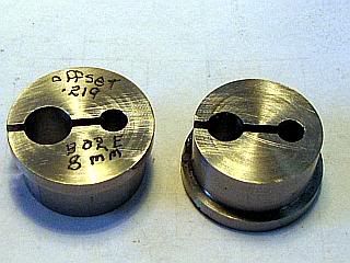
For a one piece crank I would make an offset bushing out of round stock and hold it in the three jaw. I would use a set screw(s) to hold the crankshaft and then pray to the metal gods for their blessings.
Bob
I never finished my crank (3 pc). I have the crank disk: faced, turned to diameter and the holes drilled, but it is still attached to the parent material.
I thought of doing a one piece crank. My problem is I want to keep it to scale. So at .016 diameter it becomes a little insane.
Since I don't have a four jaw this how I would attempt it....
For a one piece crank I would make an offset bushing out of round stock and hold it in the three jaw. I would use a set screw(s) to hold the crankshaft and then pray to the metal gods for their blessings.
Bob
- Joined
- Feb 17, 2008
- Messages
- 2,326
- Reaction score
- 440
Tom,
I built the original Micro HOSC and Steve built an improved version of it. Here is a photo of Steve's.

I don't remember how he built his crankshaft, but I made a split collet of brass. It was 3/16 OD as I recall and I drilled the 1/32 hole for the crankshaft in the mill by offseting the part in the mill. Then I split it almost to he hole with a slitting saw and finished to the hole with a jewelers saw with a 0.006 wide blade. I don't have a photo of it, but it looks like this only on a smaller scale and being so small it did not need the second relief hole.
Steve is active here most days so you might ask him how he did his. His member ID is:
stevehuckss396 if you want to PM him.
His plans for the micor HOSC are also in the down loads section at:
http://www.homemodelenginemachinist.com/index.php?action=tpmod;dl=item145
Gail in NM
I built the original Micro HOSC and Steve built an improved version of it. Here is a photo of Steve's.
I don't remember how he built his crankshaft, but I made a split collet of brass. It was 3/16 OD as I recall and I drilled the 1/32 hole for the crankshaft in the mill by offseting the part in the mill. Then I split it almost to he hole with a slitting saw and finished to the hole with a jewelers saw with a 0.006 wide blade. I don't have a photo of it, but it looks like this only on a smaller scale and being so small it did not need the second relief hole.
Steve is active here most days so you might ask him how he did his. His member ID is:
stevehuckss396 if you want to PM him.
His plans for the micor HOSC are also in the down loads section at:
http://www.homemodelenginemachinist.com/index.php?action=tpmod;dl=item145
Gail in NM
I made all my HOSC cranks the same way. Brass disk with shafts pressed in. My crank for the micro had a .0625 shaft and a .020 arm.
I turned the disk and drilled it. Pressed the shaft in. Then drilled the hole for the arm and pressed that in.


I turned the disk and drilled it. Pressed the shaft in. Then drilled the hole for the arm and pressed that in.
Thanks Steve and Gail and Bob...
I decided to turn from solid because I was worried that a built-up design (with press-fitting) will not hold if it ever runs... My crank disk had diameter 0.094" and width 0.023"... the shaft had a length of 0.125" 0.196" and diameter 0.032"...
I write "had" 'cause I foolishly destroyed it in the last few thou of turning the crankpin because the cutter was too low relative to the dimension of the part... I removed the bit to hone it on an oilstone and never centered it precisely... th_wtf1
Too bad...
Here's making the home brewed "collet" (sandwiched)... the 0.005" brass shims were removed so that the M5 bolt could pinch the shaft...
and here's the broken-off part, RIP on the "collet", near the screw head ... the still thick end is the crankpin at 48 thou diameter - that broke on it's way to 0.032"...
I may build it up with press-fits... but I'll give it another try to turn from solid... tomorrow... tonite I have to drawn the sorrow... *beer*
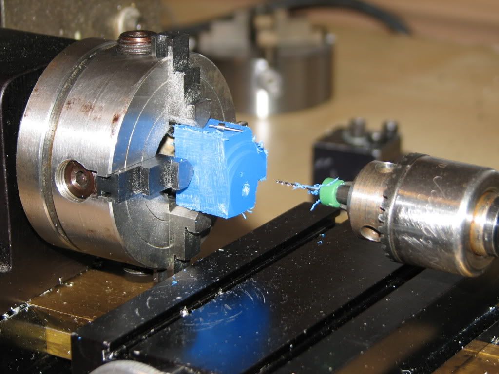
I started once more to turn from the solid... If this failed Id build it up using press fits...
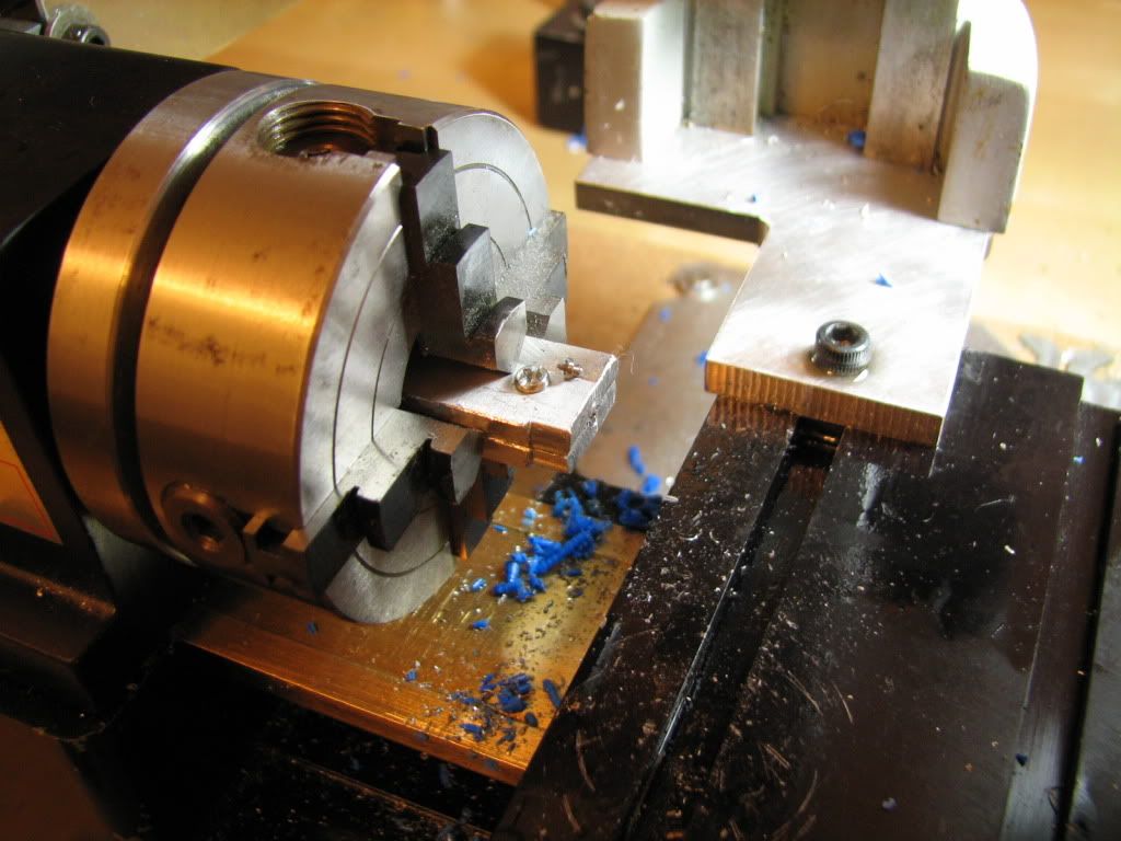
First I centered (dead centered) all my tools by taking face cuts on a piece of brass mounted on the 3-jaw... Shown is a microtool holder that I made using Luis Allys (goes by tryally on YouTube) instructions (he is the One).
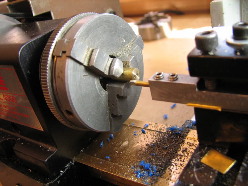
I started from a 1/8 steel shaft from a broken #80 carbide drill centered in the 4-jaw. The shaft is not carbide, only the drill is... BTW it machines beautifully... Im happy that I know my machines by now and that I can generally machine within 0.0005...
When machining such small diameters you have to step it down from left to right in small increments... if you do the whole length at once the tool will deflect the part and youll be turning a taper... Joe Martins book details how to do this...
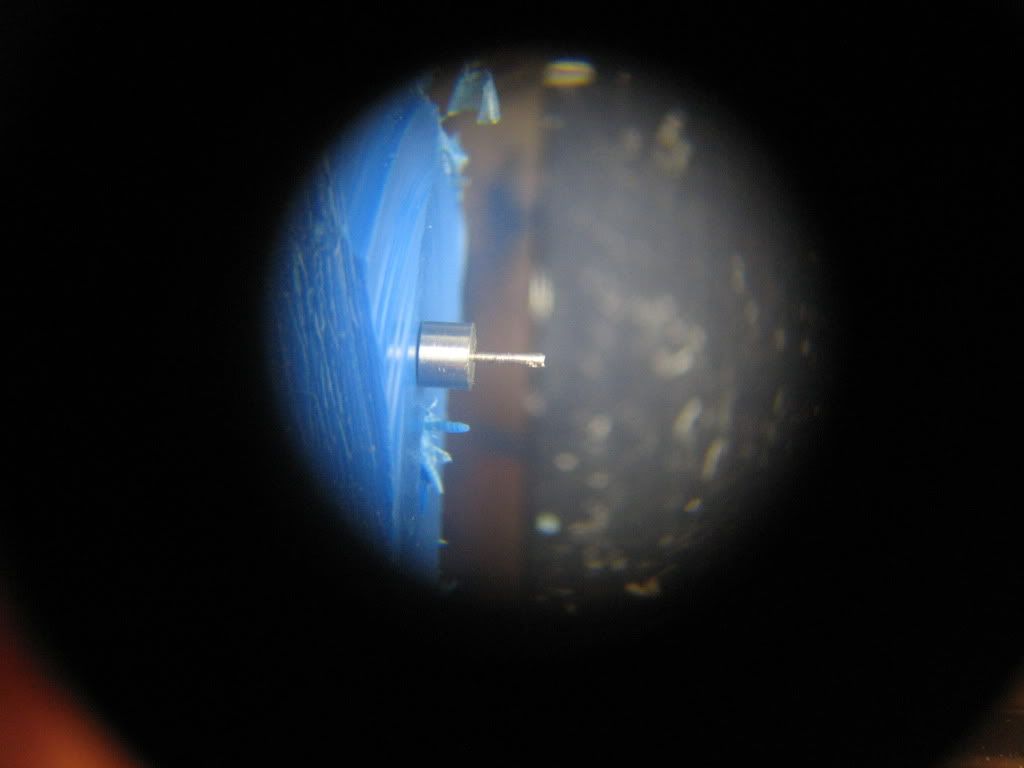
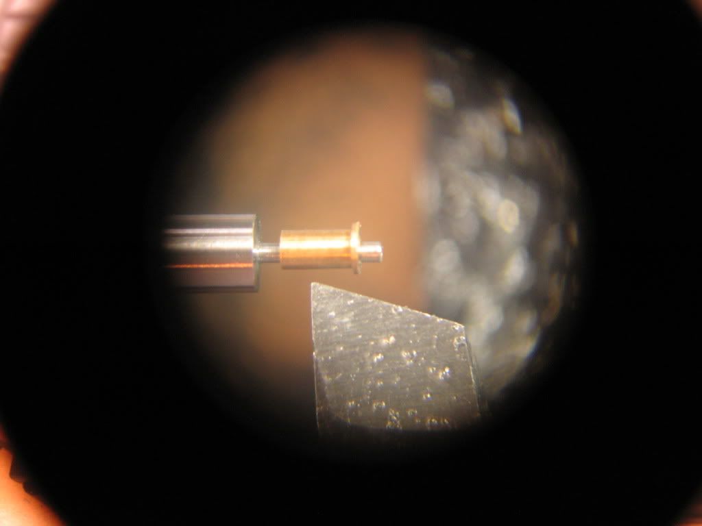
Heres the bearing, fits very nicely (as did the previous)... Note that the hole of the bearing is eccentric by 0.006 as stated above... to correct a mistake when making the column.
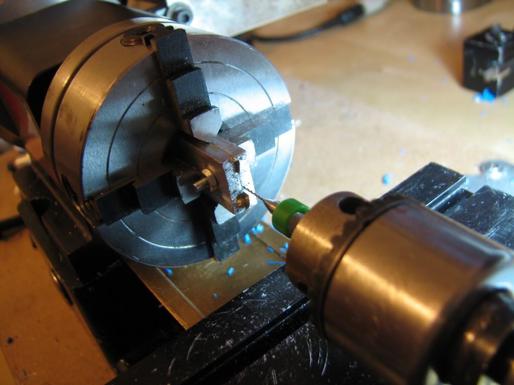
Here I have offset the shaft by 0.023 in the 4-jaw... and start turning the crankpin... with very light passes and constant honing of the tool...
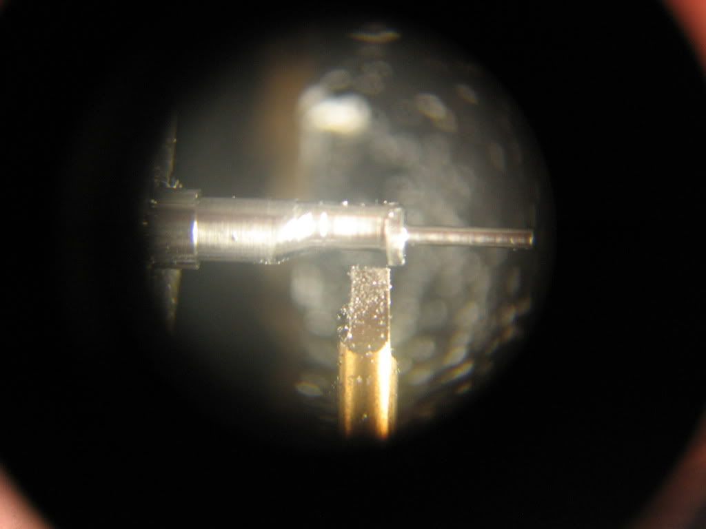
I was angling the microtool to be able to plunge it with the corner...
I then ground the microtool as a mini left hand tool that is also thin...
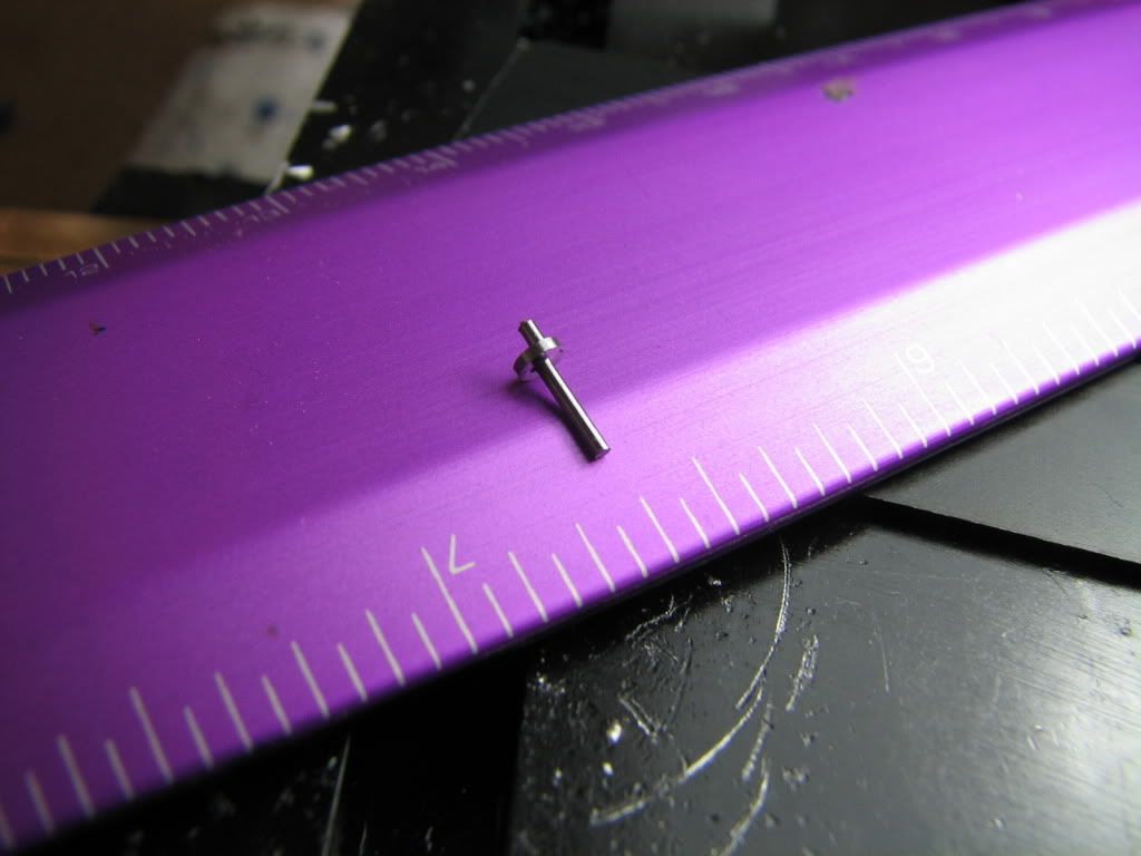
This diameter of the crankpin is 0.032 using the Mitutoyo calipers... cannot mike it in there... (it was OK in the end...)
Parting off...
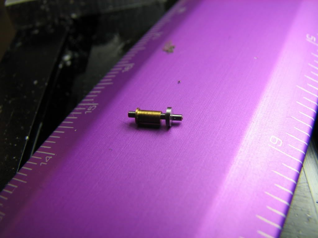
Success!
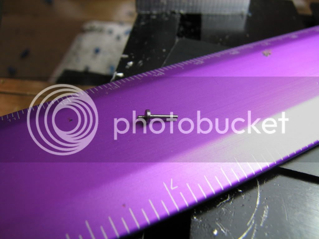
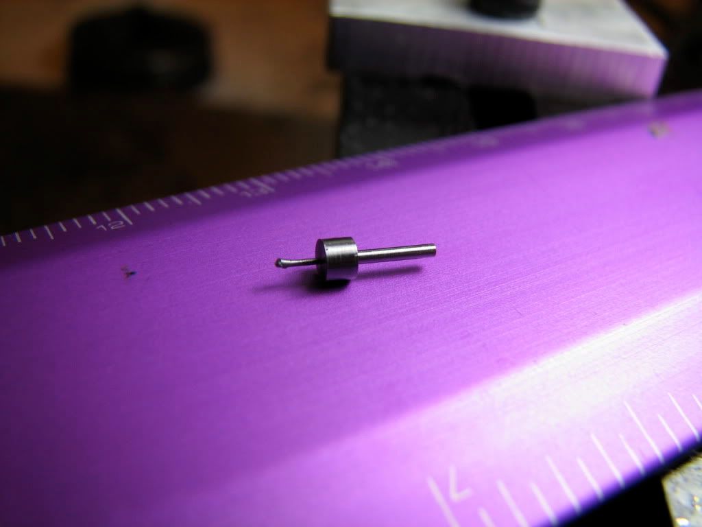
Success! Miking it I see that I have the correct dimensions... A photograph blowup and measurement suggests that the eccentricity of the crankpin is 0.022" -- good enough... Here in assembly with the bearing...
Next is the cylinder...
First I centered (dead centered) all my tools by taking face cuts on a piece of brass mounted on the 3-jaw... Shown is a microtool holder that I made using Luis Allys (goes by tryally on YouTube) instructions (he is the One).
I started from a 1/8 steel shaft from a broken #80 carbide drill centered in the 4-jaw. The shaft is not carbide, only the drill is... BTW it machines beautifully... Im happy that I know my machines by now and that I can generally machine within 0.0005...
When machining such small diameters you have to step it down from left to right in small increments... if you do the whole length at once the tool will deflect the part and youll be turning a taper... Joe Martins book details how to do this...
Heres the bearing, fits very nicely (as did the previous)... Note that the hole of the bearing is eccentric by 0.006 as stated above... to correct a mistake when making the column.
Here I have offset the shaft by 0.023 in the 4-jaw... and start turning the crankpin... with very light passes and constant honing of the tool...
I was angling the microtool to be able to plunge it with the corner...
I then ground the microtool as a mini left hand tool that is also thin...
This diameter of the crankpin is 0.032 using the Mitutoyo calipers... cannot mike it in there... (it was OK in the end...)
Parting off...
Success!
Success! Miking it I see that I have the correct dimensions... A photograph blowup and measurement suggests that the eccentricity of the crankpin is 0.022" -- good enough... Here in assembly with the bearing...
Next is the cylinder...