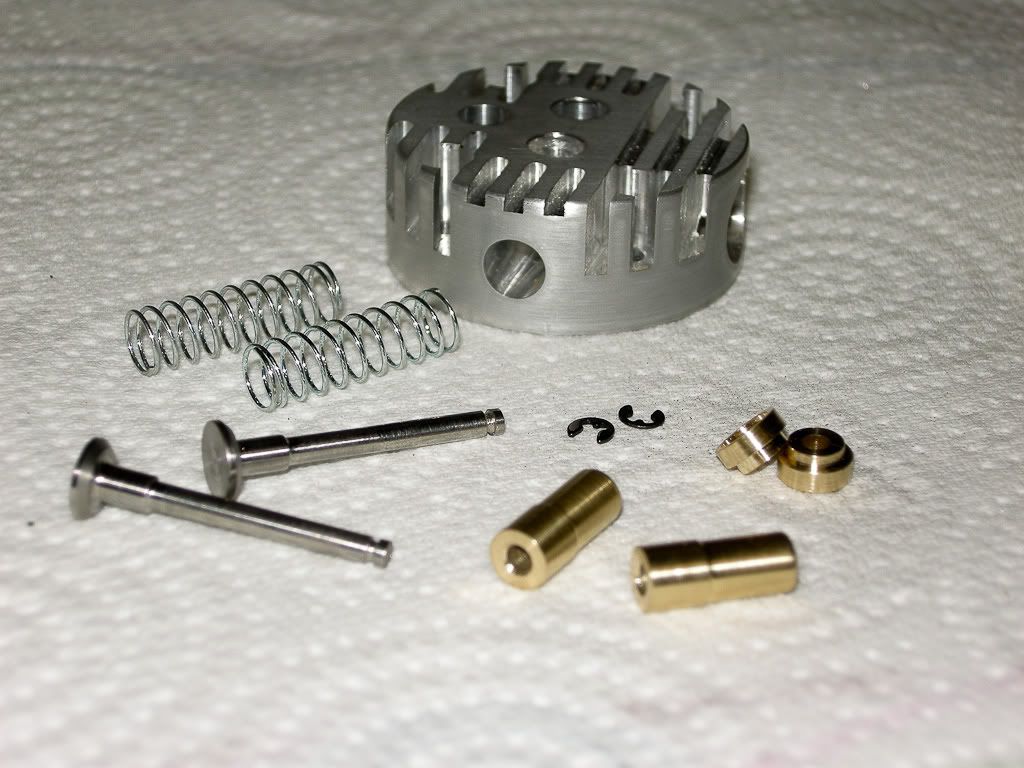
DaveRC Builds a Upshur Single Vertical engine

Home Model Engine Machinist Forum

Help Support Home Model Engine Machinist Forum:

This site may earn a commission from merchant affiliate links, including eBay, Amazon, and others.
004 – Valves, guides, springs and bits.

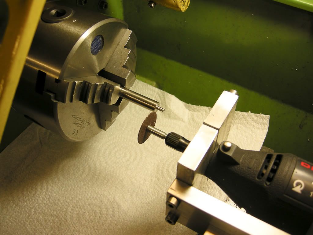
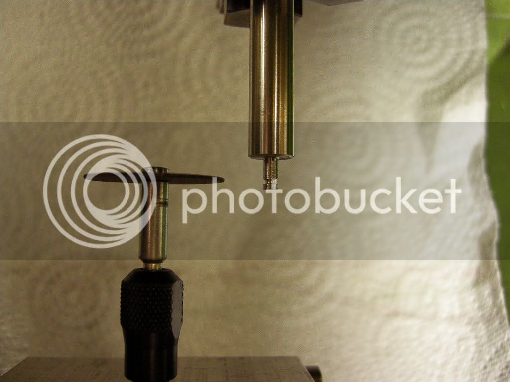
Valves, humm, first one I made is in the bin, did not get a very good finish on it and just was not happy with the way it turned out. Second one was to my satisfaction. Made out of stainless, turned down about ¼ inch at a time to stop it springing while cutting. I cut the grove for the E clip with a dermal, now I am not taking any credit for this idea I have seen this done before on this very forum, but can’t for the life of me remember who it was, but looked like a dam good idea, so I tried it.. The mount for the dermal I have I made a long time ago for a different project and been using it for all sorts since. The holder replaces the tool post, it did the trick.

DSCN1450.jpg

DSCN1451.jpg


Finished valves

DSCN1453.jpg


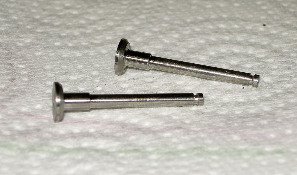
Valve guides made from brass and the caps as well, springs I had kicking about.

DSCN1452.jpg


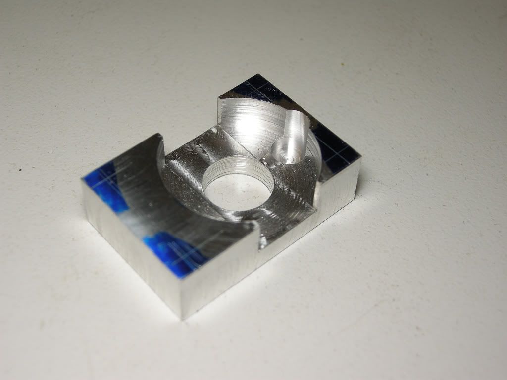
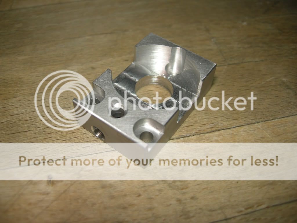
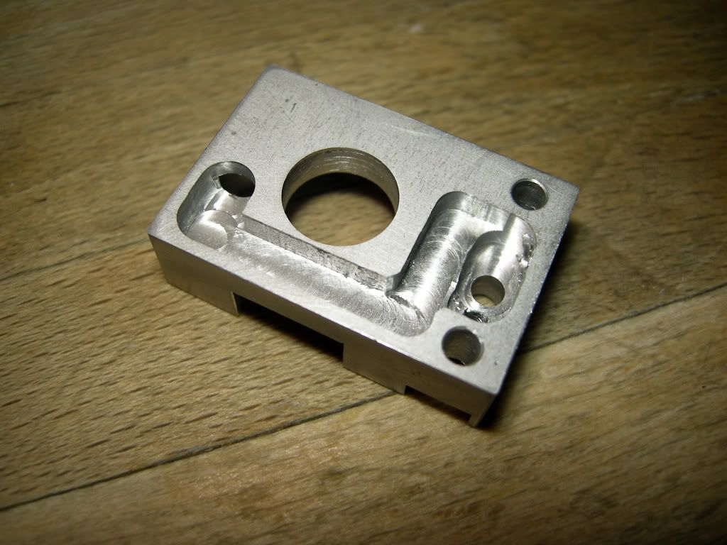
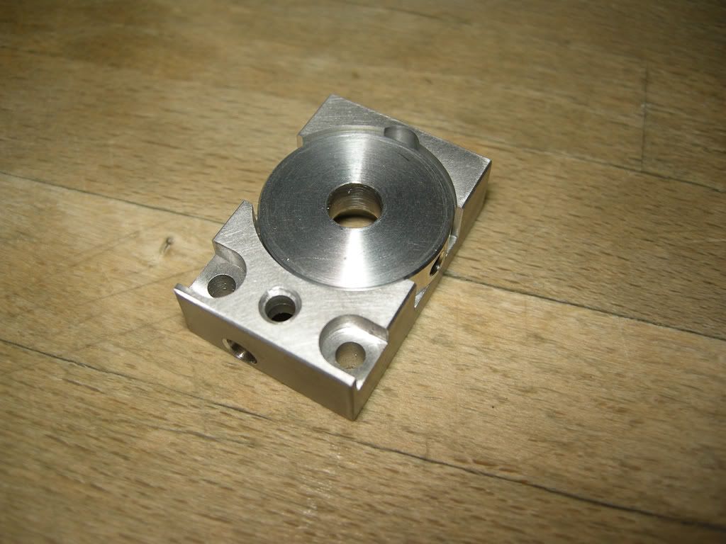
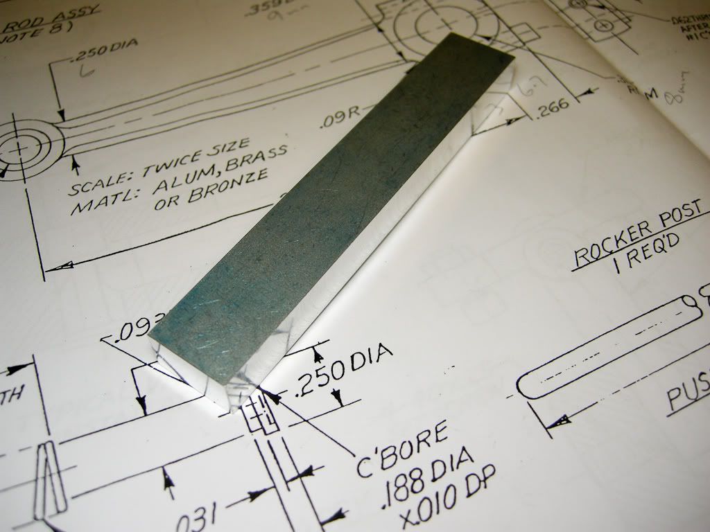
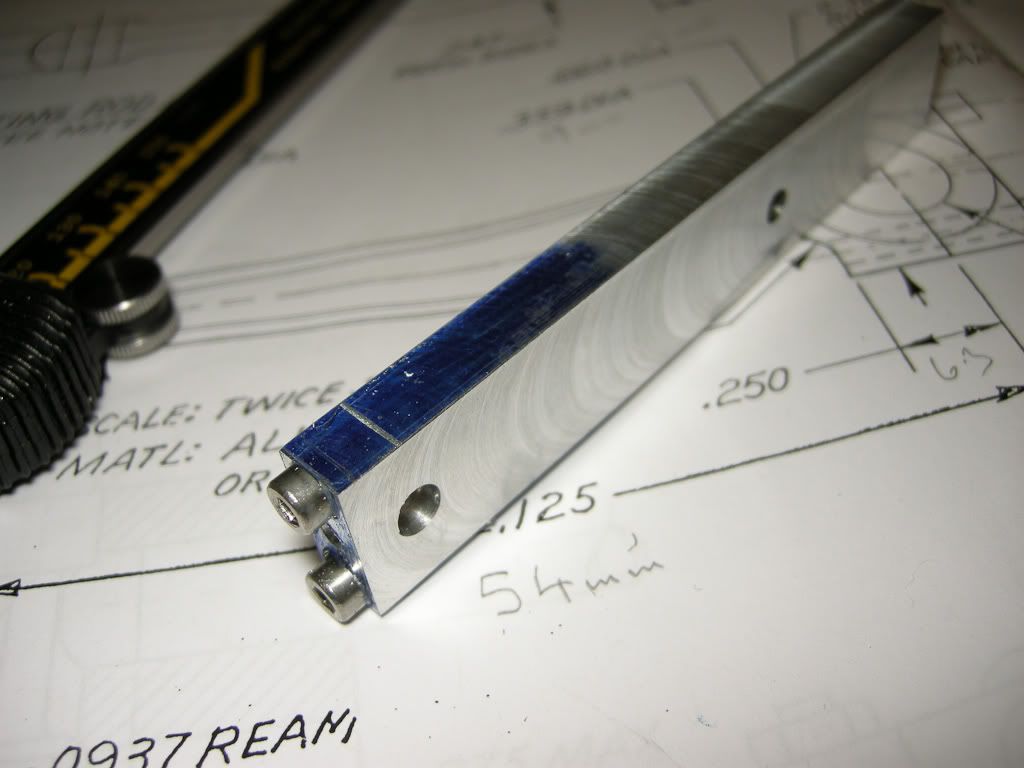
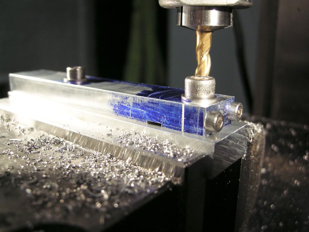
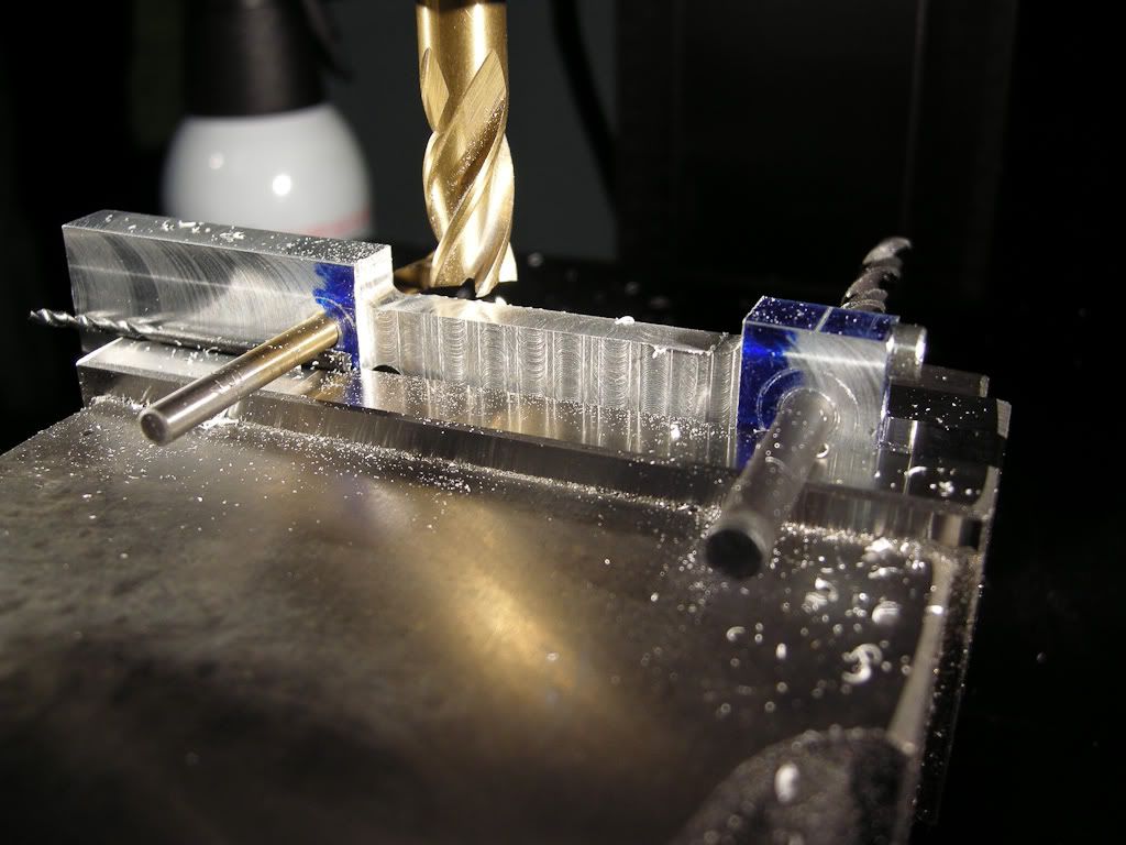
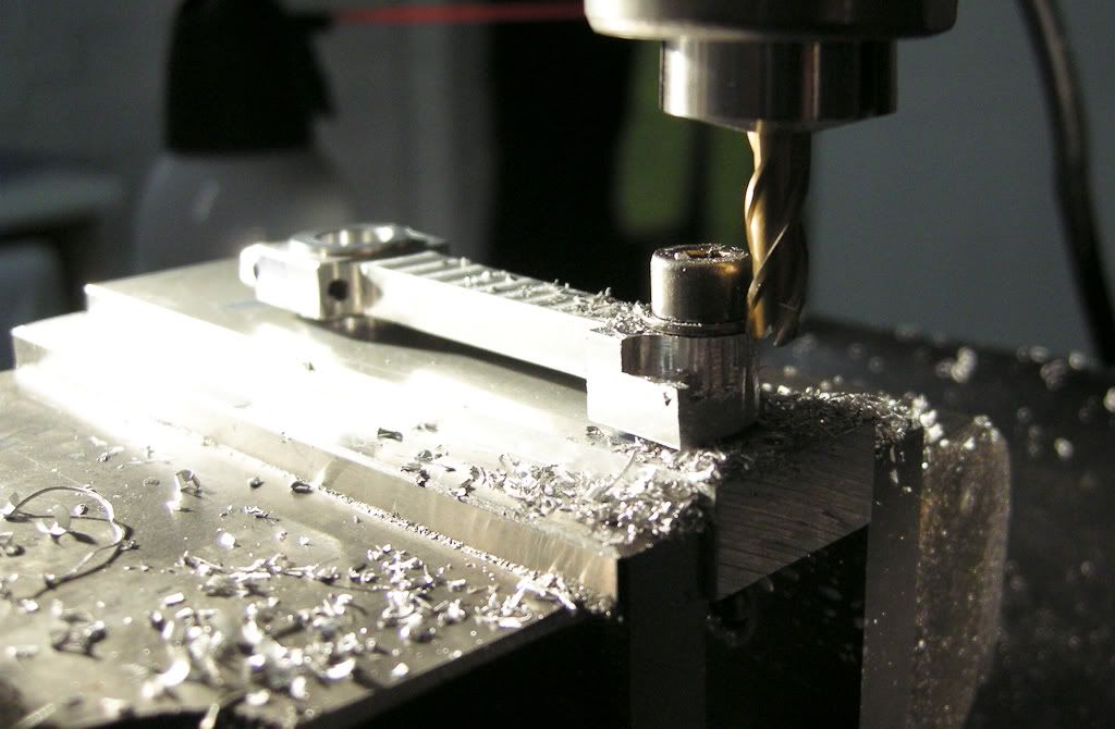
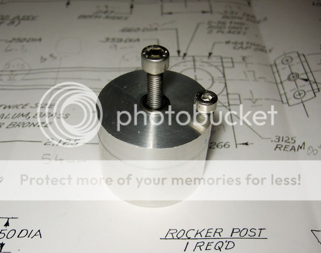
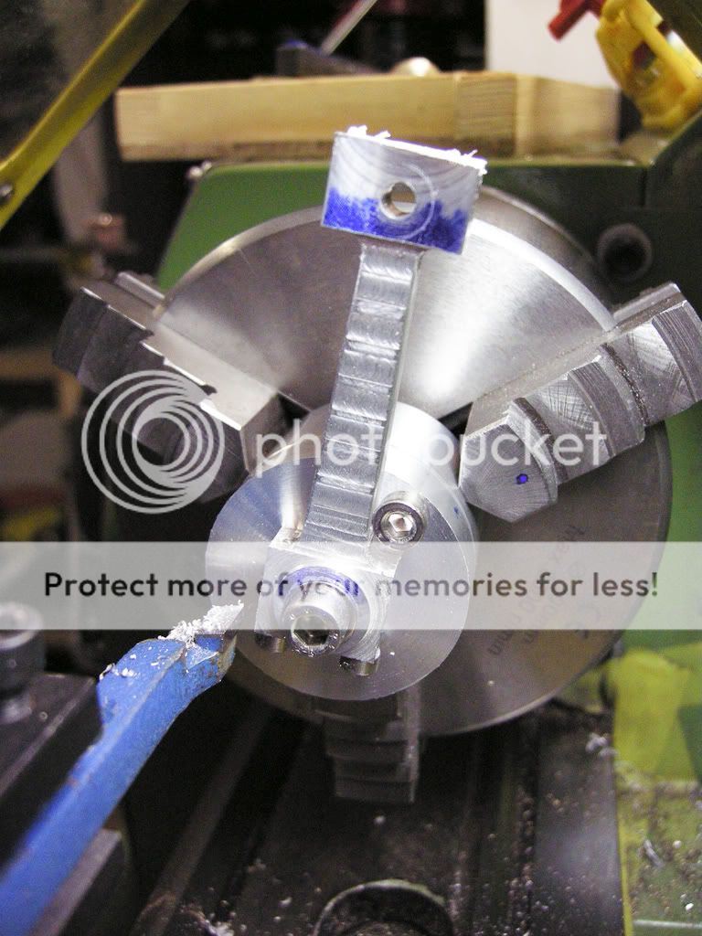
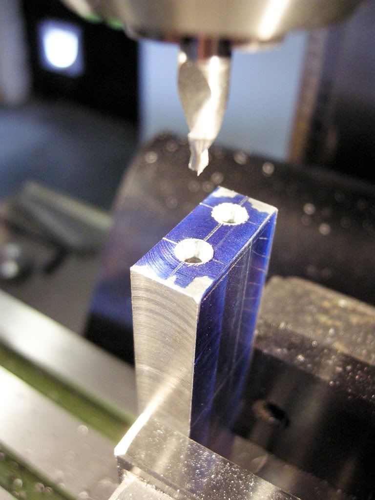
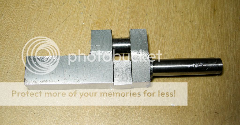
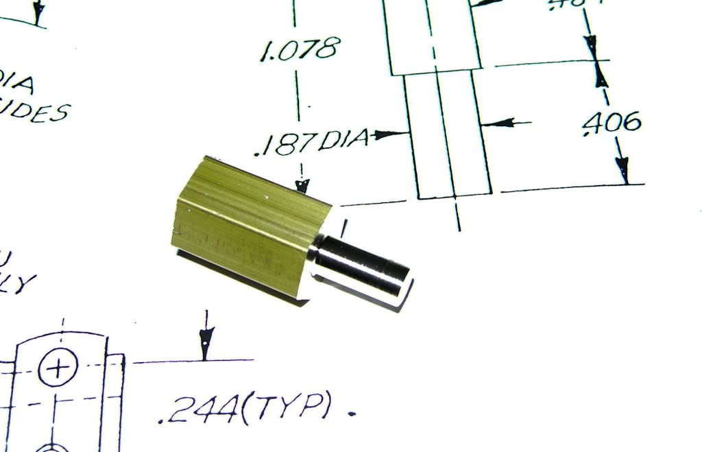
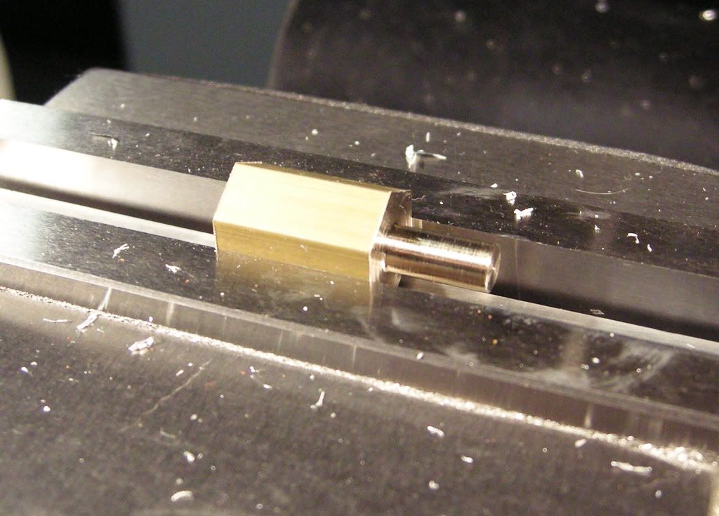
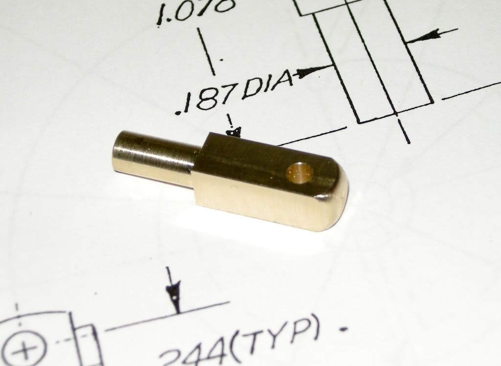
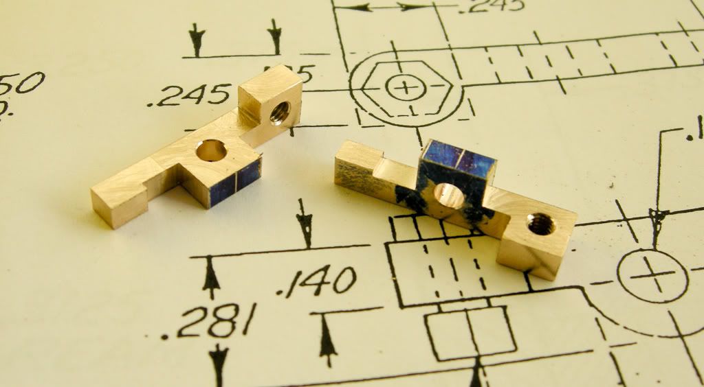
Next was the rocker support. I have probably made this back to front, I am sure others would have made the square post first and this with a 4 jaw in the lathe turned down the mounting post. I did this the other way, I used a bit of hex to start with, turned down the mounting post and then it was easy to mount in the mill to make the square post.

DSCN1464.jpg


DSCN1465.jpg


DSCN1468.jpg


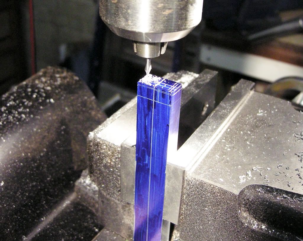
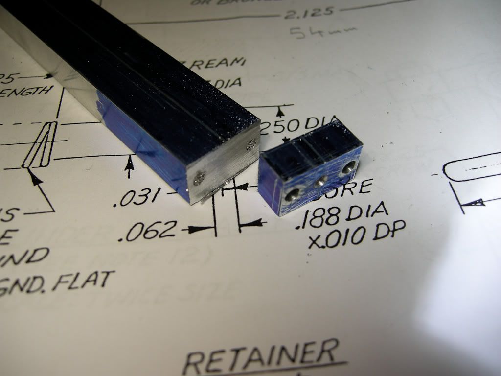
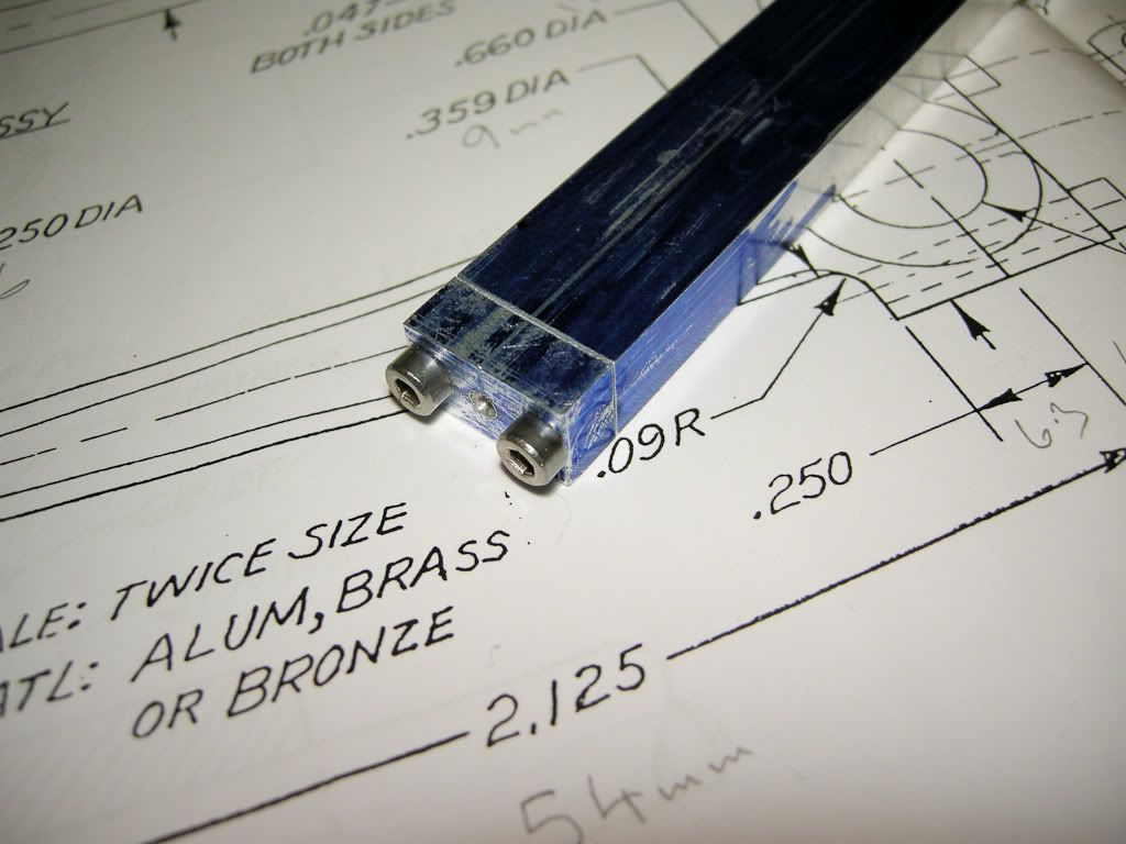
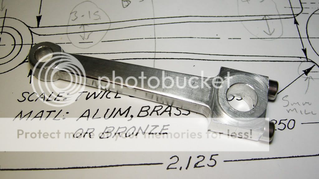
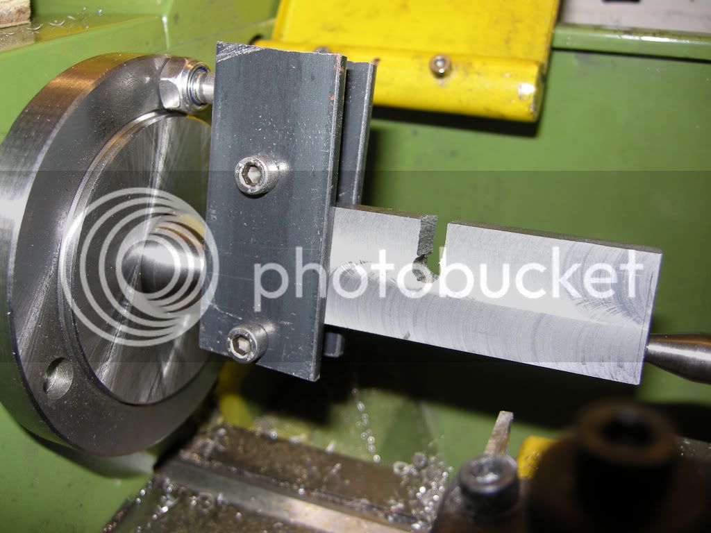
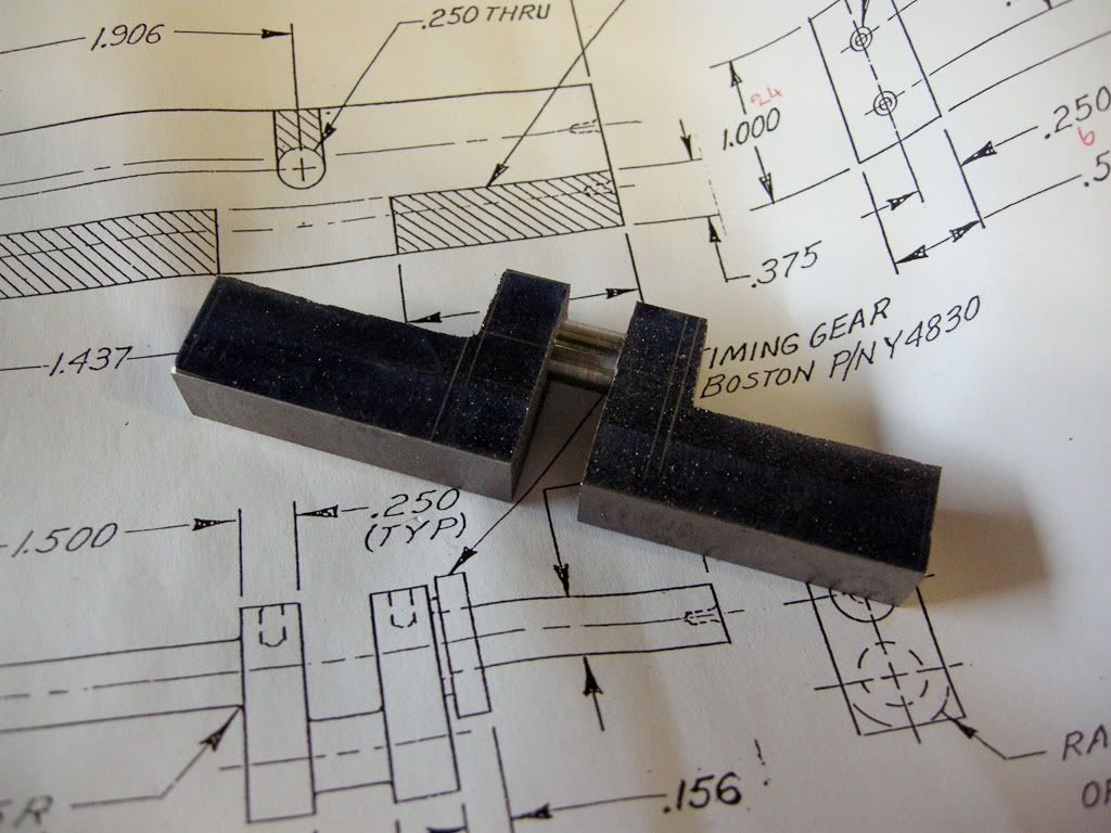
Next was the rockers, wow, these were a pig to make. I thought I would be clever (bad idea) and make the basic shape to size for both at the same time in one long bit, then cut them in two to finish off. First problem was the mill bit slipped in the collet (never happened before) and dug in to it, first bit in the :toilet:. Next I got myself confused with the left and right handed bits and cut them the wrong way, next bit in the :toilet:… So I decided to mill one at a time, much better, I did bolt then back to back to finish off, but it was worth the effort and I think they look good, the final rounding was done with a drum sander in the dermal and then finally with a file.

DSCN1471.jpg


Last was the rocker shaft, tried to follow the original plan and drill and tap the ends for some very small bolts, just could not get it to dill small enough in something so small and hard. Gave up and used 2 more E clips.


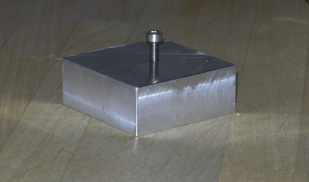
With the valve guides finally glued in there final resting place, there where a good push fit but a bit of loctite on them just to make sure. I put a small bolt into a block to act as a stop so they would go to the right depth and not go in to far, I put the head over the bolt through the valve hole one at a time and pushed the guide in to the stop. I was dreading doing this as I don’t think the Loctite gives you to long to mess about.

DSCN1481.jpg


005 – Final assembled Head woohoo1

And this is it, the final assembled head. I am so impressed with the way that all came together. I am sure only you guys on here can appreciate how happy with the result, my wife gave it the same appreciation as she would to something the cat dragged in….

Anyway, gold head, thought it was a nice touch. The fins will be going black, not sure about the crank case yet…

DSCN1488.jpg


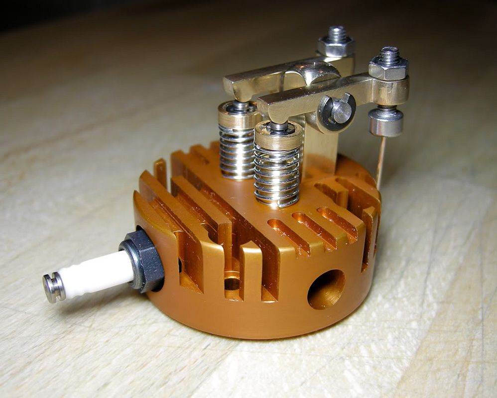
The gold anodising dye is strange stuff, its clear green in colour and watching the head turn gold in it was very odd….
 
Well done and nicely documented Mr. Dave. Thanks.

-Trout
 
Hello Dave,

I am new at this myself and have just completed my first engine, a Duclos Fire Eater. Starting out with the Upshur Vertical is quite a feat but from your build so far it appears you have the 'knack' or whatever required - looks great! I'll likely start on one of these today after seeing your and MBs' build logs.

One question: I also have done some anodizing with mixed results - not bad but not great. I've used Rit dyes instead of the purpose-made ones and wonder if that is the big variable. That gold head looks fantastic and seems to me to be the right color to really complement one of these little jewels.

I'll be watching this thread for future developments.

Best,
Mike
 
Hi Mike,

Yes the anodising, been doing it a while now and I was also getting very mixed results with the dyes. I found company selling different dyes from what I was using. I contacted then and they supplied me with some small amounts to try out (very reasonable cost as well) the dyes were very different from what I was using, came in powder form and had to dissolve this in almost boiling water (all water used in mixing the dyes should be distilled). But the main difference with these are the operating temperature is around the 40 to 50C mark (no hotter then this or the part starts to seal). Black and Gold are the only two colours I have tried so far, but the results are consistent and good, the black is black, very deep and as if it came off the end of a production line. The other colours I have, but yet to try are, Blue, Red, Green, Orange and Violet.

This is the company I now get my dyes from.

http://www.gaterosplating.co.uk/index.php

If you want more info, or if anyone else wants info them maybe I should start another thread, I got loads of info and it's not that hard once you sorted the bits out.

 
Hello Dave,

It sounds as though we've had parallel experience with anodizing. There is a company here as well that sells small amounts of the purpose-made dyes for anodizing and I've just not been too active with it recently to give it a try, but definitely will be going that route, especially if you say the black comes out with the deep lustre - that's the hardest one for me.

Attached are a couple of photos of some things I anodized - a toolpost holder for my Foredom grinder and an optical center punch. The holder came out OK - I didn't prep the surface sufficiently as I was just going for the hard coating. The Optical center came out well with a deep blue finish.

Looking forward to more posts on your Upshur!

Best,
Mike

DSCN7871.jpg


DSCN7848.JPG
 
Dave,
incredible job on the head. I woul.d like to see a thread on anodizing if you have time to put it together.

Randel
 
006 – Hall device pickup holder thing….

No updates for a while, I got distracted by my first grandchild coming into the world last week, so no time to get into the shop…. Anyway young Oliver is doing well….

Also got totally sidetracked by MB, I had on the bench ready to do next was the con rod and crank. Then in the post came the TIM-6 ignition unit and I had been thinking about mounting the pickup and then MB put up his pickup mount and then I had an idea in my head and could not get it out so ended up making it… ::)

The one I have made does not give such an easy solution to adjusting the timing, I am hoping once set I will not have to touch it. I had in mind a contained unit so it was totally shielded and protected and just a single cable. I picked up some shielded cable from the local Maplin, they have some 4 core screened cable that is just over 3mm dia, very small indeed. Looking at the TIM-6 I see that the hall device only needs 2 of the wires plus the screen, also on the TIM-6 there is a timing LED so thought is may be cool to incorporate the LED in the mount, this only need one wire, plus the shield again.

No drawings, well some sketches on some post it notes, made most of it out my head. :idea:

As usual I forgot to take enough photos, before I knew it I got it almost done.

DSCN1492.jpg


The hall device is buried deep in the block and will fix it in using silicone, along with the wires and LED. Included is a VERY small screw in the back to use as a ground point for the screen, must remember to remove the anodising around the area under the screw as the anodised layer does not conduct electricity and would make it pointless. The disk is held on with a couple of grub screws that can be accessed from the side and holds the extremely small rare earth magnet.

Done, this will bolt onto the back of the engine, two bolt holes and the LED in the middle under the disk that will hold the magnet.

DSCN1494.jpg


It’s a bit fiddly in the back, good job I am use to working with very small electrics, so should not be a problem. The cable will have a dab of epoxy on the inside to hold it in place and should all look nice and neat.

Back view, channel cut out for the wire, hall device at the top

DSCN1497.jpg


And the final photo, for now, showing the disk in place, the magnet is a rare erth magnet and very small.

DSCN1501.jpg


Next is to get it anodised, will do this when I get a batch of bits to do. Black body and gold disk I think…


The next instalment should be the con rod and then the crank. I have been thinking ahead and one of the things I had been playing with in my mind was the tank, now I have seen another update from MB about the tank, I must resist and get on with the tank….. dam, crank, crank, crank….. :wall: :wall:
 
Congratulations... Grandpa! :)

Your project is looking good and moving along very well! :bow:

The Upshur model your building is considerably more complex than the farm models.

I'm looking forward to seeing your completed project!

-MB

 
Hello Dave,

Congratulations on your grandchild - best thing that can happen to a man; my granddaughter is now almost 14 (going on 23!) and is a great joy to us.

The build is looking great and I am looking forward to the Black and Gold anodized parts (Pittsburgh Steeler football fan.)

Can you give more details on the ignition setup? I'll likely start my build of the Upshur momentarily and would like to know which ignition system to order. This being my first IC engine, I'd like something that's as trouble free (and idiot proof) as possible.

Best,
Mike
 
Hi, Thanks guys, it's an odd feeling now being a grandpa, but a good feeling... ;D

MB, you think this one is more complex then the farms engines...? Really, did not think there was much in it. After watching your build I am seriously thinking about building one of Hamiltons farm engines, a water cooled version, really like the look of that one, and very curious about the hit-n-miss....

Mike, Pittburgh Steeler football fan eh, oh well, trust me the colours have nothing to do with football (I am not a football fan). I have other colours but I do not want to introduce any others as I would like to keep it as classy as I can...

On the ignition, this is my first engine and not got any experience with model ignition, I am using the TIM-6c kit mainly because it looked simple. I am not looking for performance I just want the engine to tick over so was just wanting something that worked. I will however report my findings when I get round to it and no doubt I will be setting up some sort of test bed to check it all out.


Right, onto,

007 – The Con Rod

Needed to do this before the crank so I have something to check the fitting when making the crank.

Interesting little part was this, but fun to make.....

First job was to find a suitable material, the plans say brass, bronze or aluminium, well I have no brass or bronze big enough but did have some aluminium plate, which I think is more Dural than Aluminium. Anyway, it’s quite hard so I hope it will do the job.

Cut out a strip wide and long enough and squared it all up on the mill, including squaring up one end. Blued it all up with a marker pen and marked out centre lines along the face and end, and marked out the end for the holes for the bolts.

DSCN1502.jpg


Drilled in the end a hole for each of the bolts, drilling the hole for the 3mm thread first, then opening up to 3mm clearance for the bolt in as far as where it will be cut and also drilled out the oil hole.

DSCN1503.jpg


After this I cut the end off,

DSCN1504.jpg


Then back in the mill to square up the cut. Threaded the body and then fitted the end back on, looks like it was never cut off…

DSCN1506.jpg


After this it was back in the mill to drill the holes for the crank and wrist pin. Now I drilled the holes a size smaller then needed, this is so I can use the holes to bolt the thing in place on the mill while I was shaping the rod.

DSCN1509.jpg


Took off the recess on each side, then off the base plate an mounted the part in the vice on it’s side.

DSCN1511.jpg


I used a couple of drills through the holes to get the level and calculated then the small end needed to be raised by 2mm to get the correct angle, so used another drill to use as a gauge to raise the height. It sort of worked and sort of pleased with the results.

DSCN1515.jpg


For the small end I tried bolting it back through the hole and turning the part by hand to shape the round at the top. This did not go as well as I expected and ended up finishing it off with a file, still a bit rough and needs a bit more work before I am happy.

DSCN1520.jpg


Made up a mandrel in the lathe to hold the rod while I cut the step in the side face of the big end of the rod, this seems to go well.

DSCN1525.jpg


DSCN1517.jpg


And this is it finished, but I think I want a bit more file work on the small end.

DSCN1524.jpg


It was an odd part to make and I made some mistakes (tiny ones), mainly to me rushing it, did not have a lot of free time over the weekend, so not giving it the care I should have done, if this part was visible I would have thought about starting again. But I think I am getting fussy now and the more I do the more I spot my own mistakes so all part to the learning curve.

Dave
 
Congratulations are in order for both you and your daughter. :bow: Now onto things of lesser importance (depends on who you talk to), You are doing some terrific work there Dave and the results have been spectacular. The clarity of the photos coupled with your narrative makes me feel like I'm right there along side. That crankcase is another great example of profile engineering that truly will set this engine off when it gets displayed. Keep slogging away and we will be here looking over your shoulder anxiously awaiting the final video.

BC1
Jim
 
008 – Crank shaft

Wow, I can’t believe I have had so little time in the shop, this is just not on. I have been itching to get in there but it’s just one thing after another, very annoying..

Progress is VERY slow and frustrating and other projects keep coming up and getting in the way, but I will get there eventually….

I did at last manage a few hours last week and over the weekend so started work on the crank.

Never ever done anything like this before and been getting very worried about this, so taking it one step at a time. First I got myself some black steel, which was way to big… Still no power saw so using good old elbow power cut a bit off and cleaned it all up in the mill.

DSCN1489.jpg


Marked out and while in the mill drilled the centres needed on the ends.

DSCN1527.jpg


Now to mount in the lathe, very interesting job this, never turned a piece between centres like this and took a bit of thought, well for me it did anyway… But I got there in the end and it seemed to go well.

DSCN1531.jpg


Managed to turn the pin fine, very slow, but it went OK. One thing I did find out, and I am sure I have seen it said, black steel is hard to get a good finish on it… Well I can vouch for that, it’s a right pig of a job to get a good finish. I found a very sharp HHS tool and some suds worked the best.

Anyway, on to the rest of the shaft, back in the vice and out the bulk of the unwanted bits with the hacksaw again.

DSCN1532.jpg


After one side was done

DSCN1536.jpg


I mounted it in a collet on the lathe, first time I have ever used a collet on a lathe as well… seemed to work well on the other side.

Got the bit on the bench and was checking it all out with the callipers and realised I had made a mistake, I had misread the plans and the 0.132 width of the gap for the con rod, I had used for the shoulders and it should have been 0.250, ooops, back in the lathe and took a bit off. Good job it was not the other way around….

Anyway, sorted,

DSCN1537.jpg


So this is as far as I got, the crank still needs some more work, needs a good clean up, need to make the counter weights and the shaft need to be turned down buy 1mm to fit into the ball races

Next instalment with be in about a month at the rate I am going, not the best but it’s still going in the right direction.

Dave
 
Thm: Good looking crankshaft Dave. Glad to see you have some time to work on the upshur.

ironman (Ray)
 
Dave

As I have just started on the Upshur vertical 4 stroke myself and in the midst of machining the six crankcase plates I came across your build thread and your inspired interpretation of the plans is making me seriously consider a fresh start.

Your clear photos and your problem solving approach will be a huge help to me.

Thanks Dave and I am sure you will keep up the good work.

John-Som
 
Hi,

Glad you found it useful, but I am still not 100% it's going to work, I can't see why not though....

My building of this has come to a grinding halt. Other projects from some other interests have taken over so I have not go any further with this, no doubt I will get back to it at some point as I have gone way past the point of no-return, probably will be left for a winter project now to finish.

Dave
 
Hi Dave

Maybe it's the uncertainty of success when we take on a new challenge that drives us forward. In other words if success was guaranteed from the outset where would be the fun ?

I for one was disappointed that you will not be continuing the build of your Upshur in the immediate future. Having made a second start on my own engine things are progressing albeit slowly. The Upshur is a small engine, certainly when compared with my last engine build (Jan Ridders' Simple Two Stroke) and I have arrived at the conclusion that the time taken to machine components increases as the size reduces.

So far the crankcase has been completed apart from a little shaping of the exterior. With the con rod completed I am now working on the crankshaft though I have chosen the built up version.

I do hope we will get to see the completion of your Upshur complete with mandatory video.

John


Back
Top