DaveRC Builds a Upshur Single Vertical engine

Home Model Engine Machinist Forum

Help Support Home Model Engine Machinist Forum:

This site may earn a commission from merchant affiliate links, including eBay, Amazon, and others.

DaveRC

Well-Known Member
Joined
Dec 4, 2010
Messages
83
Reaction score
4
My first engine build.

I have been wanting to build an IC engine for years, never had the time or tools to do this. Last year I got myself a lathe and this year got myself a mill.

Now I have the tools, I looked for a simple’ish build I came across the Upshur Single Vertical 4 stroke engine and ordered all the back issues of Strictly IC that cover the build.

Now with all the plans, read everything I could find on it I got to work. First thing I do not work with imperial very well so started to convert everything to metric. Lots of discussion on here about how to do the conversion, ended up leaving some of what I call the critical stuff, piston, crank, crank shaft, cams etc in imperial and the rest to metric.

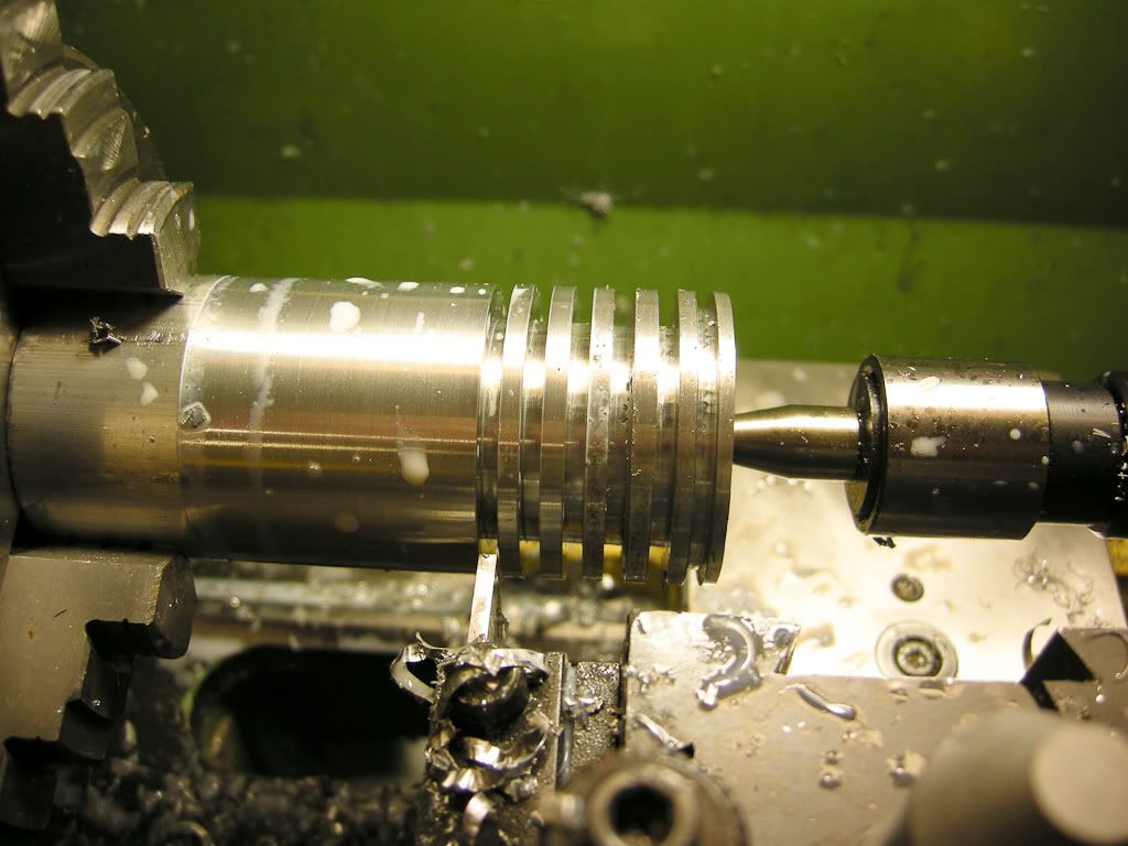
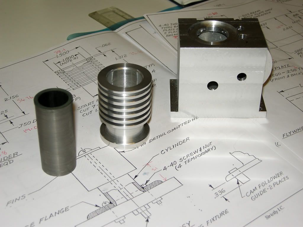
Even though I was determined to build it as the plans and not to change anything I ended up changing a few bits before I even started. First thing was the main body crank case. The plans show six separate parts to the body plus extra parts to make the gear cover that sticks out the side, I have cut that down to two parts by making almost a casting from a solid block and making a cover (back). In doing this I can’t make the cylinder as the plans as it was to solder onto the top cover. This is good as I did not like the idea of this anyway and made up the fins to come all the way down to bolt onto the main body, this also allows me to make the cylinder out of cast iron as it now just a liner.

So a couple of significant changes to the build, the other change was to replace the bearings on the two shafts with ball races, I had a big selection in the draw and was a simple (ish) task and as the bearings where quite thin there was enough room to counter bore then in from the inside of the housing.

First entry - The crank case

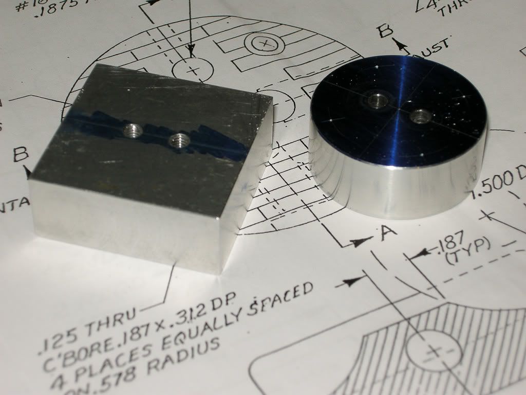
Take one big chunk of Ali

DSCN1371.jpg


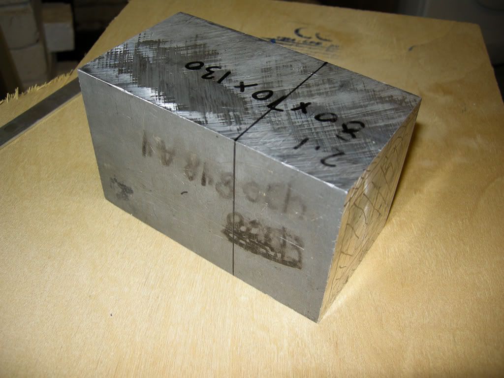
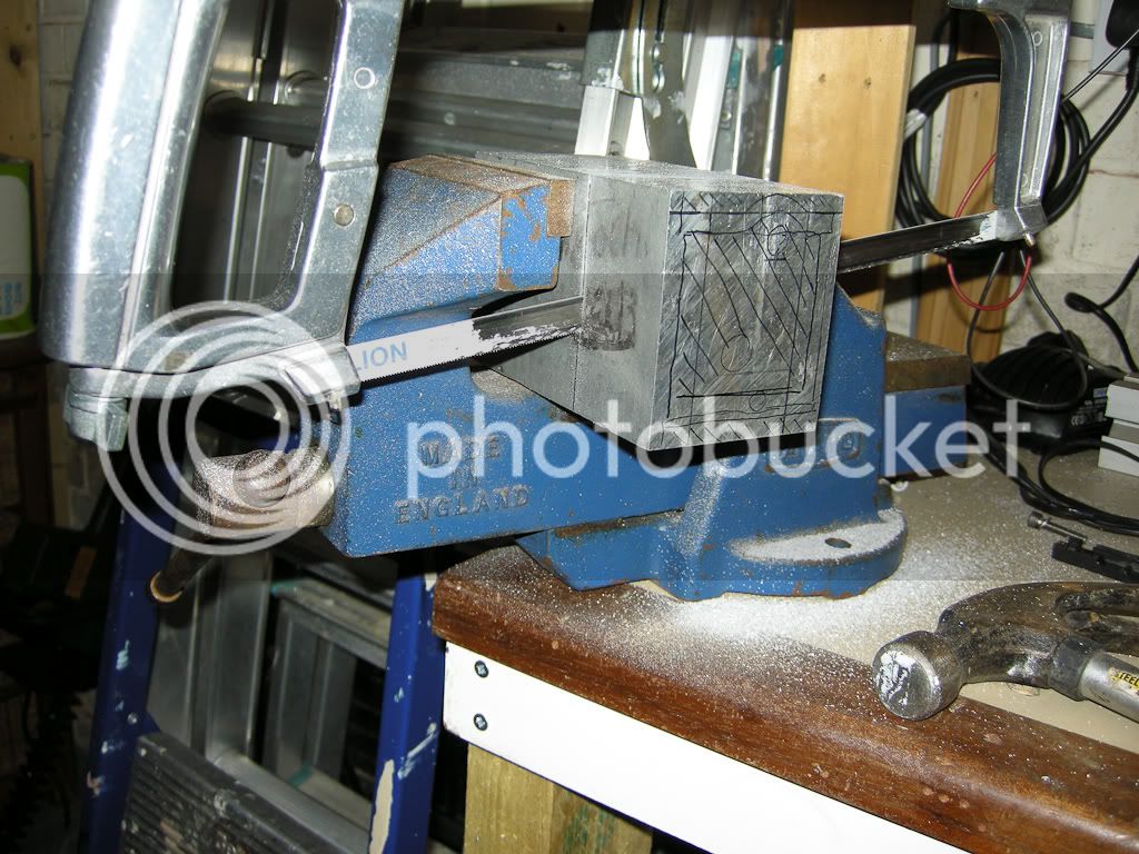
Cut a lump off, (must buy a bandsaw, that was hard work..)

DSCN1385.jpg


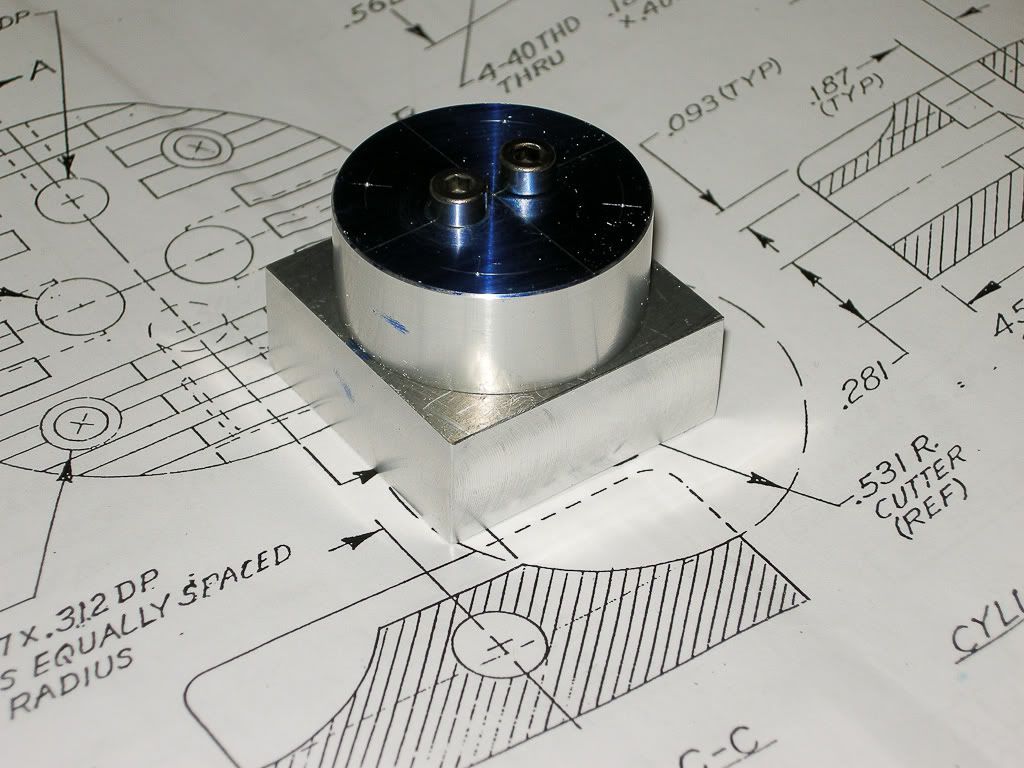
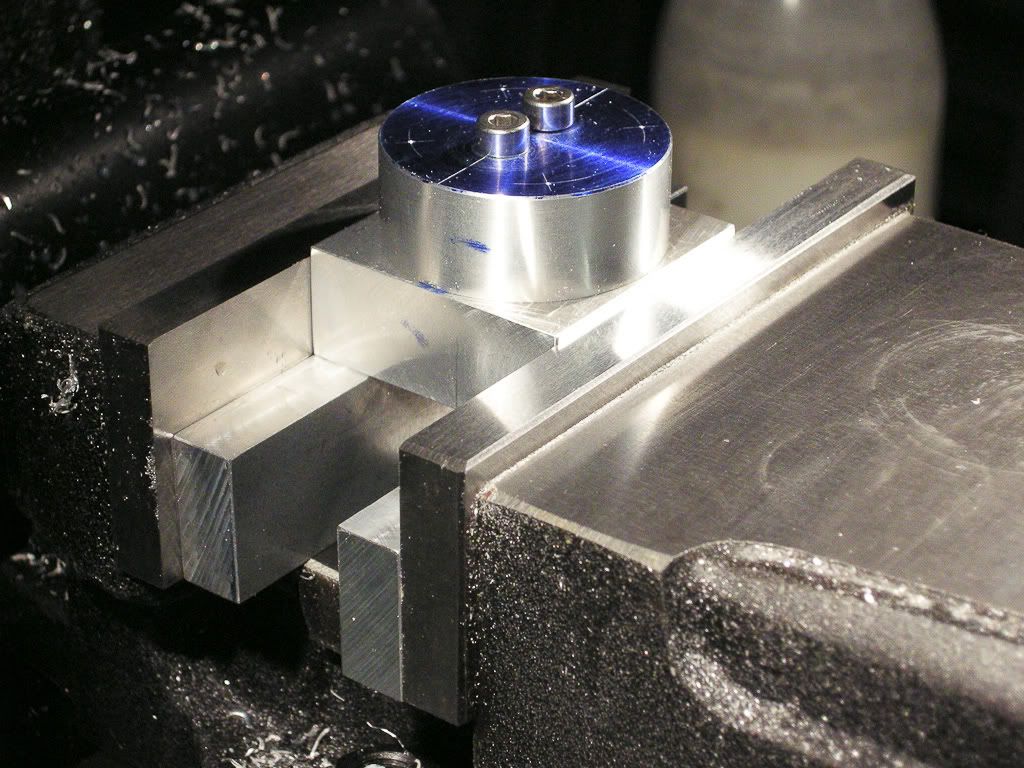
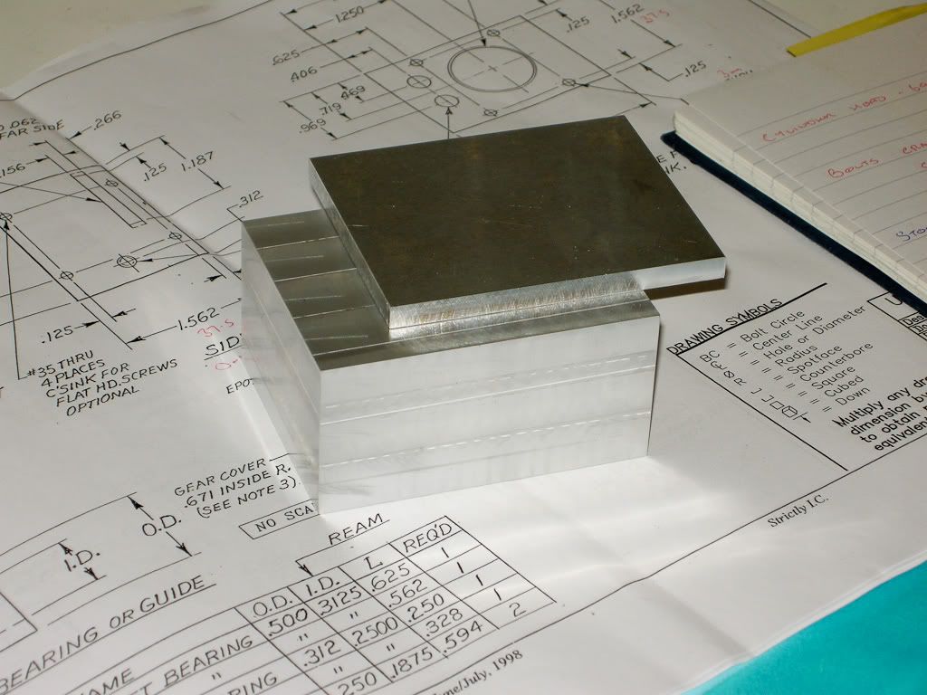
Trim it all up on the mill and the cover all to size

DSCN1390.jpg


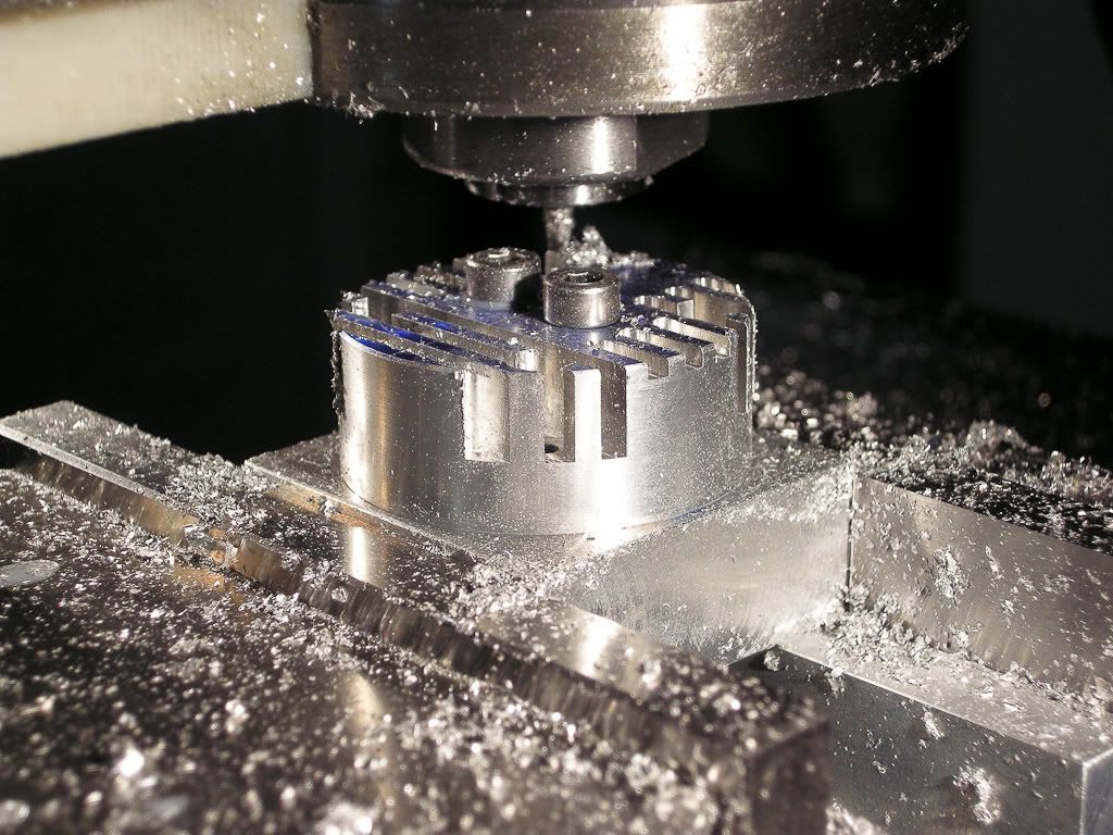
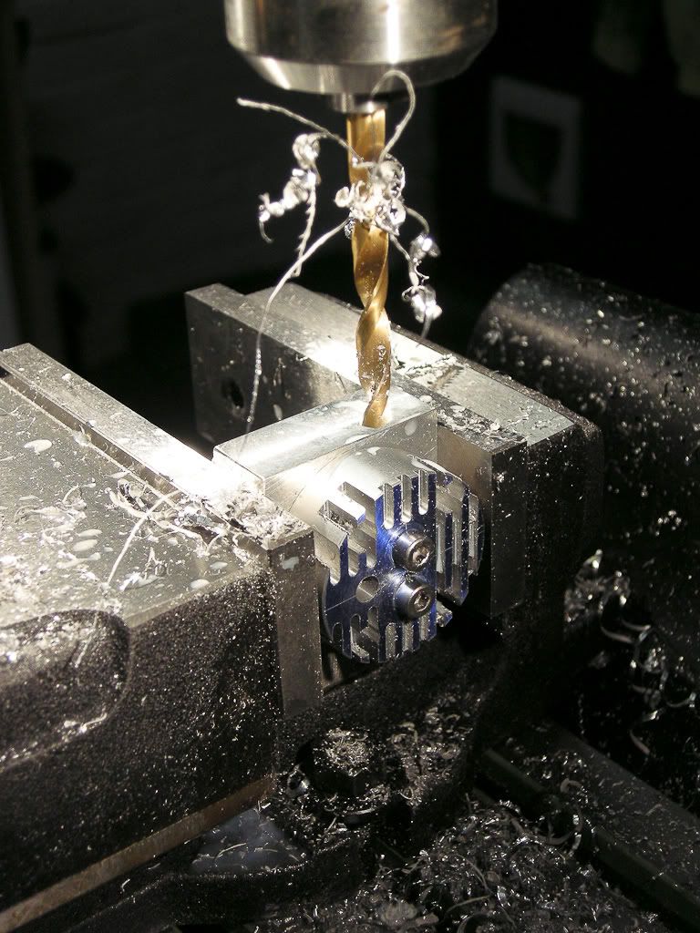
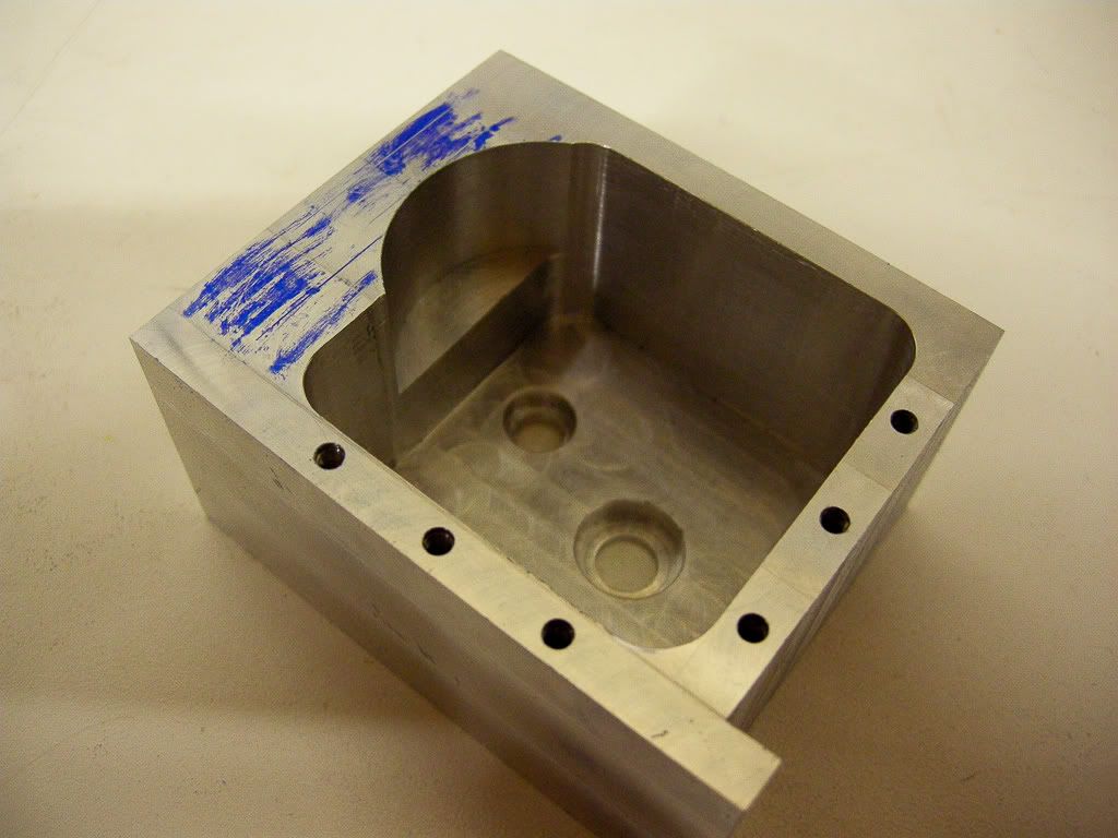
Start milling out the inside
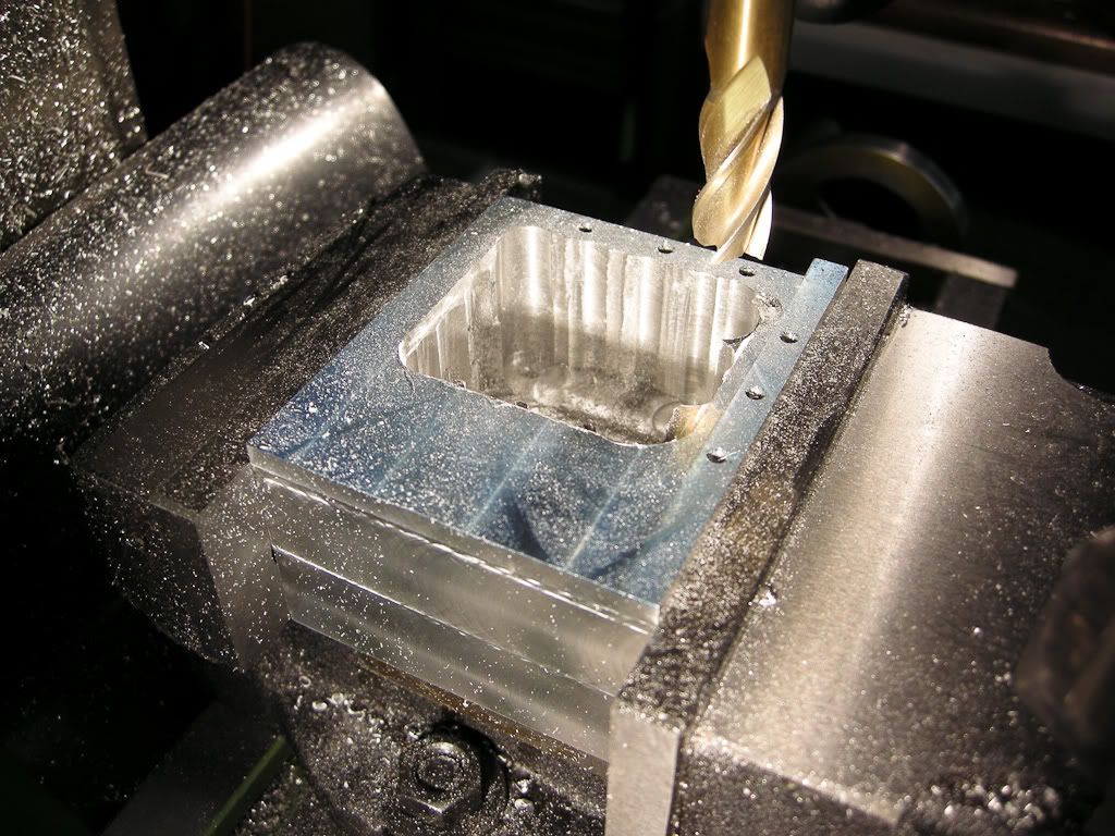
DSCN1394.jpg


Until you get this

DSCN1396.jpg


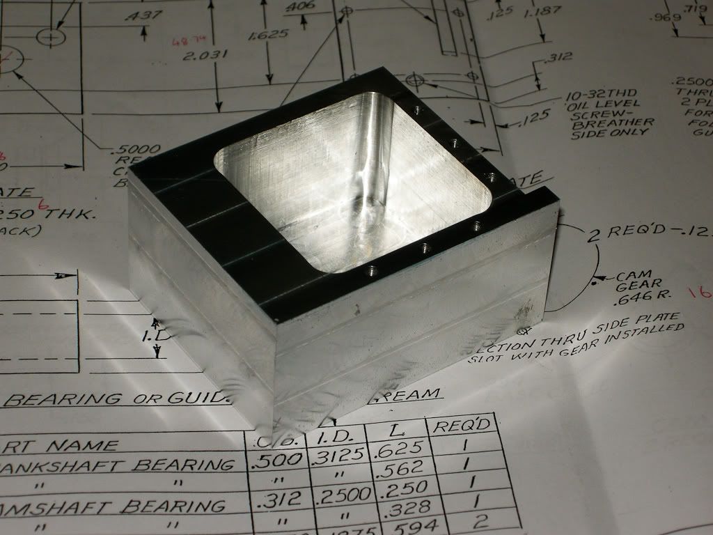
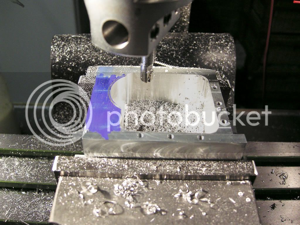
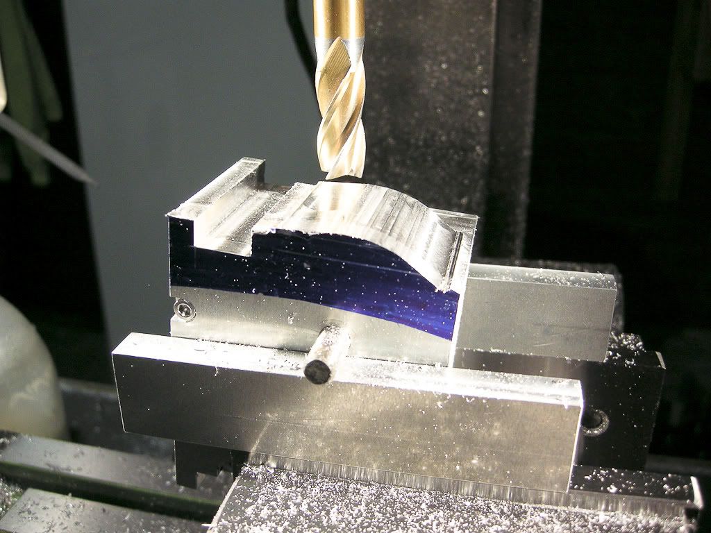
Then start forming space for the gear

DSCN1402.jpg


end up with this

DSCN1404.jpg


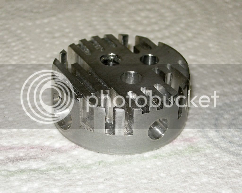
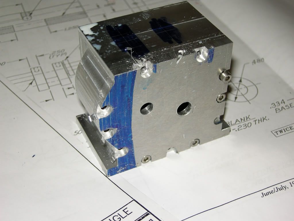
Then start shaping the outside

DSCN1406.jpg


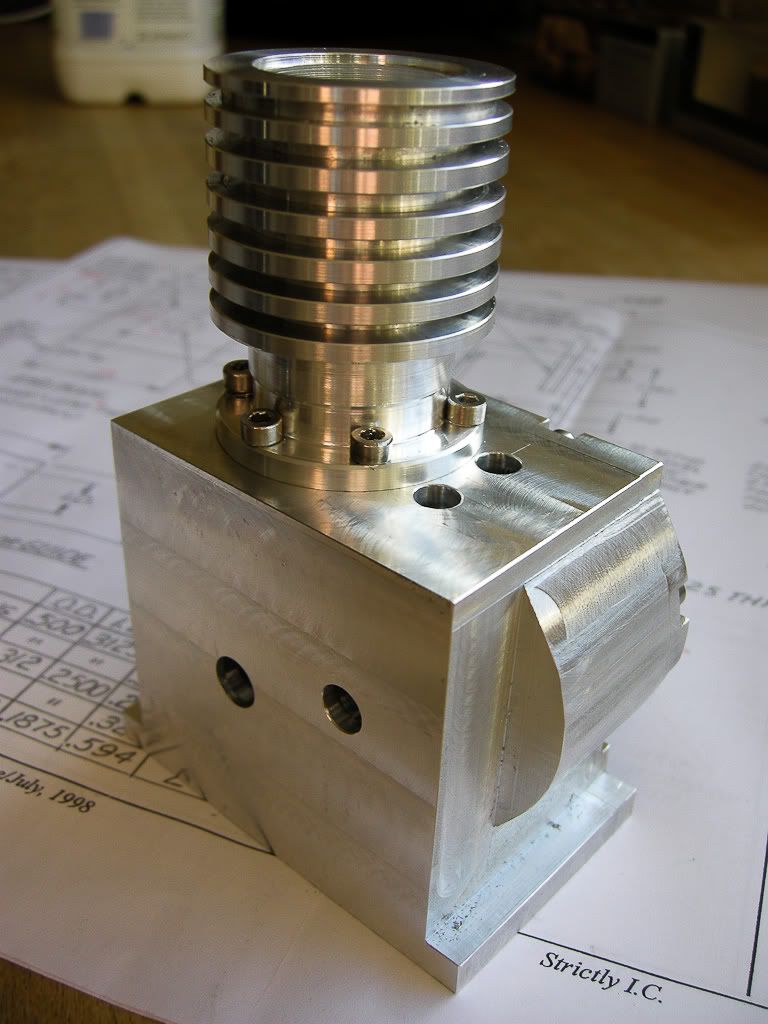
Finaly I ended up with
DSCN1408.jpg


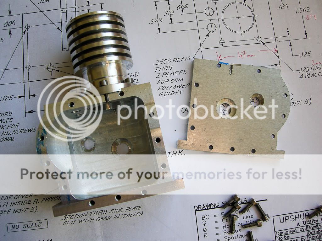
and with the cover off

DSCN1411.jpg


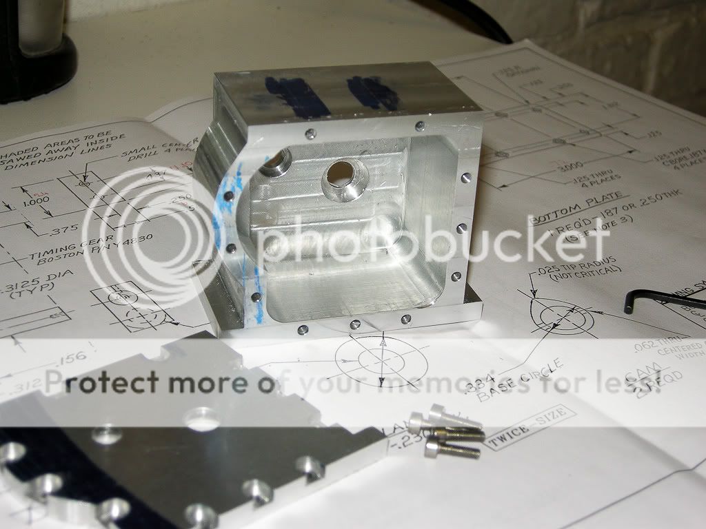
It's a start, more photos and updates soon.

Dave
 
Looks Marvelous!!! Is the style of this engine going to be the same as one of MetalButchers Upshur engines?
 
Off to a good start Dave. I'll be following along. Do you plan on making the flywheels and gears or purchasing?
 
Well, yes, sort of.... I have been following MB thread, I actually started this some time ago before I had seen his work, but only just got around to posting the progress. But I must admit I got lots of tips from following his work, as well as a big pile of inspiration ;D

Also I am only building one, I think one at a time is enough for me... ;)

flywheels, not sure what I am doing there yet, as for the gears, I got two gear cutters on the bench ready to make my own, now thats going to be fun, never cut gears before :eek:
 
lookimg great Dave
is this a hit and miss engine?
How about posting a pic of what the engine will look like when finished :)
 
The usage of a manual hacksaw as well as a file for profiling builds character (hurts like you know what at times but it builds character nonetheless) ;D Great looking start Dave, I've always rather fancied the uprights.

BC1
Jim
 
metalmad said:
lookimg great Dave
is this a hit and miss engine?
How about posting a pic of what the engine will look like when finished :)

Hi, no, it's not a hit and miss, normal 4 stroke.

As for the final photo, I don't actually have a photo apart from the one on the front of the mag, it's here, number 2

http://hamiltonupshur.tripod.com/
 
Excellent start Dave! I like the way you milled the rounded profile. :)

Using a hack saw is a nice touch. I still use mine once in a while.

A 4"x6" H/V powered band-saw is in stock somewhere... and waiting for a home.

Give it a nice home Dave. ;D

-MB
 
Metal Butcher said:
Excellent start Dave! I like the way you milled the rounded profile. :)

-MB

Yeah, now where did I see that done before..... ;)
 
DaveRC said:
Yeah, now where did I see that done before..... ;)

I'm smiling Dave! You just made all my efforts worth while! :)

-MB
 
Good going Dave. That was my "get your feet wet" ic engine. Wish I had thought then to use a block instead of all those capscrews and that little side cover for the gear. Was an experience never to forget.

Great work. Keep it up and more photos.

ironman (Ray)
 
It`s looking good so far!
Keep sending pictures, i promise i`ll keep watching!

Norberto
 
Thanks for the comments guys, will try to keep this thread going.....

002 - Next update, must take more photos, I get carried away some time and keep forgetting to take the photos, even though I keep the camera on the bench… Must try harder…..

Anyway, making the “fins”, which originally was supposed to be just the fins and not come all the way down to the base, well as I changed it I needed to bring it all the way so I could bolt it on to the base.

Fins in the making. I was reading up on MB progress on making the fins and he talked about quite a bit of the old chatter when cutting the fins, common problem with using a parting off tool I think, well it is with me. Anyway MB got round it mainly by lowering the speed of the lathe, well I had not tried that and dropped the speed to about 300 RPM, would you believe it worked a treat, still got through quite a load of suds, but it did work.

DSCN1416.jpg


Cylinder, The bit of cast iron I got was a bit on the small side, did not realize until I cleaned up the outside. I ended up with a liner that is fine apart from the lip at the top is not very big, I think it big enough but may think about remaking it before I fit it, would prefer it to get a better seal. It a very tight fit and will need to heat the fins to get it in, but need to anodise the fins first.

DSCN1417.jpg


And with the fins bolted onto the base, looking good I think. One of the screws was a bit tight and has come through on the cover, I did not realise, not a problem and will not show when the cover is on…

DSCN1425.jpg


But it looks cool all bolted together

DSCN1421.jpg
 
Nice progress and a nice photo coverage. I had wondered how the radiused side covering the timing gear was cut. I learned something from your pictures!

Thx...
Chuck
 
Hi Dave, your project is looking really good!

I simplified my cylinders and eliminated the the use of a cylinder liner, by making four of my cylinders from one piece of cast iron. I tried cutting the fins at @400 and got the worst chatter imaginable. Based on Georges (gbritnell) recombination I dropped down to the lowest speed on my lathe @130 and that solved the problem. Since I bored out the cylinders before cutting the fins I couldn't use a live center. I'm sure that this also added to the chatter problem.

Looks like you have a good handle on chatter, and using the fluid was a good idea.

-MB
 
Nice work---One of these days, when I recover from the Kerzel, I'm going to build something with an enclosed crankase like that.--It'd be nice to have at least one engine that doesn't spew oil everywhere while its running!!!!----Brian
 
Thanks again for the comments guys, feedback is always good (good or bad) as this is my first engine and thinking about what I am doing this is also the first of anything I have made like this that actually has more than a couple of parts, it’s quite a different challenge making something like this that is a complete “machine”….

003 – The Head

Was not looking forward to making this, quite a lot of work on one small part, my worry was one mistake and having to start again…! But as it seems the metal gods are with me and so far it’s all gone according to plan, but still, plenty time left to go wrong yet….. ;)

I turned up the blank in the lathe ready but I knew I have no V clamps so could not hold it in the vice on the mill, I made a base/holder up. Drilled through the head where the valves were going but with smaller hols than needed for the valves (so I had room to drill them out later), but just the right size for a couple of M5 bolts and carefully drilled and tapped a couple of M5 threads into the base.

DSCN1431.jpg


And with the blank head mounted on the base

DSCN1432.jpg


With this it mounts in the mill very nicely.

DSCN1433.jpg


On the original plan was to use like a slitting saw to cut the fins, I did look into getting a slitting saw but thought I may try a different way. I got myself some 2mm long reach mills, wow, there are small and paranoid I was going to break them (OK I did snap one, but not while cutting, I caught one of the bolts when moving the bed to cut the other side of the head, good job I had backups), taking VERY small cuts at a time and just increasing the depth 0.5mm at a time and did it all very slowly.

DSCN1435.jpg


Drilling the side ports and hole for the spark plug was easy with the head in its mount.

DSCN1438.jpg


So, finished, all clean, all holes the drilled and reamed to there final size, the only thing I have not done is cut the seats for the valves, this will be done after it’s been anodised and everything else fitted. Yes, watch this thread, I have a small anodising setup at home and a good selection of dyes and been getting some great results….

DSCN1454.jpg

 
A good wheez, that mounting block, one well worth remembering. Nice work on the head - it's a credit to you!

-One of these days, when I recover from the Kerzel

Rof} I thought you were building another 99 of 'em Brian - to use up all those 1/8" balls.
 

Latest posts

Back
Top