Brian,
Thanks for posting your gear cutting adventure. I bought a shaper for this type of gear work but I have never put it to use yet.
Jerry, I think that I followed your first explination but thanks for adding it to this thread with more detail.
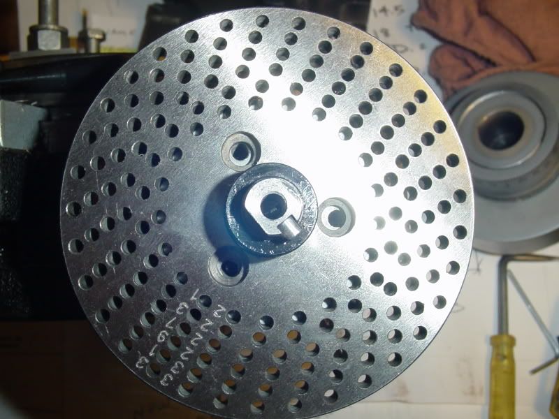
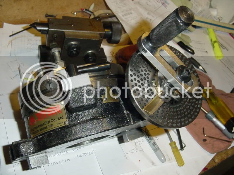
Kvom, The plates I have for my RT do not have every division between 2 and 100. It has most of them but not all so if an odd prime number gear was needed the only option would be by degrees.
Dan