You are correct.. I was overly rude to several of the good people on the HSM forum that are both helpful and productive (Mr Stevenson included). I apologize to them as it was a comment addressed not particularly at Brian's thread.Artie said:Gday Shred, Id have to disagree... I know a few of them from other sites. They do put out some great work... I think they just arent game enough to display it... might be a reason for that.... from what Ive seen on Brians thread.... would certainly make me think twice....

You are using an out of date browser. It may not display this or other websites correctly.
You should upgrade or use an alternative browser.
You should upgrade or use an alternative browser.
Cutting my first gear
- Thread starter Brian Rupnow
- Start date


Help Support Home Model Engine Machinist Forum:
This site may earn a commission from merchant affiliate
links, including eBay, Amazon, and others.
Dan Rowe
Well-Known Member
- Joined
- Feb 12, 2010
- Messages
- 594
- Reaction score
- 18
Brian,
I read the other thread and some interesting points were made that I had to take some time to think about.
I down loaded the dfx version of the Rush gear site here:
http://www.rushgears.com/Tech_Tools/PartSearch5/partSearch.php?gearType=SPUR
I set the drawing to show all the points and the gear curves are circular segments. I do not have Ivan Laws gear book but the method of using disks to make cutters has appeared other places. I can not remember the name of the gent who presented it in "Strictly IC" several years back, but i did not grasp it at the time.
Most of the methods using form cutters whether they are commercial cutters or not are only approximate methods. The commercial form cutters cut a range of gears which even if the involute curve is accurate for the middle of the range it would not be precisely accurate for the ends of the cutter range.
I located the centers of two adjacent circular segments and here is the drawing.
The single tooth in the upper section of the drawing is the Rush gear in black and a generated profile in red. The red profile was generated with a program that will generate most gears with standard geometry and a few modifications can be made.
http://delphusa.com/index.htm
I had to really get in close to see the difference of the two teeth in the section of the curve above the pitch circle. The only difference is the part below the pitch circle. There is slight undercutting with the generated gear and with any form cutter this will have to be ignored.
Thank you again for trying this and giving all us gearheads something to think about.
Dan
.jpg")
I read the other thread and some interesting points were made that I had to take some time to think about.
I down loaded the dfx version of the Rush gear site here:
http://www.rushgears.com/Tech_Tools/PartSearch5/partSearch.php?gearType=SPUR
I set the drawing to show all the points and the gear curves are circular segments. I do not have Ivan Laws gear book but the method of using disks to make cutters has appeared other places. I can not remember the name of the gent who presented it in "Strictly IC" several years back, but i did not grasp it at the time.
Most of the methods using form cutters whether they are commercial cutters or not are only approximate methods. The commercial form cutters cut a range of gears which even if the involute curve is accurate for the middle of the range it would not be precisely accurate for the ends of the cutter range.
I located the centers of two adjacent circular segments and here is the drawing.
The single tooth in the upper section of the drawing is the Rush gear in black and a generated profile in red. The red profile was generated with a program that will generate most gears with standard geometry and a few modifications can be made.
http://delphusa.com/index.htm
I had to really get in close to see the difference of the two teeth in the section of the curve above the pitch circle. The only difference is the part below the pitch circle. There is slight undercutting with the generated gear and with any form cutter this will have to be ignored.
Thank you again for trying this and giving all us gearheads something to think about.
Dan
I read all of your post, find them informative and useful. This play by play of gear cutting you presented is clear and concise enough to encourage myself to give it a shot. It is understood that the gear formed through this method is not perfect, probably will sing a little, gives it character. You formulated and tried a method to produce a workable gear for what this forum creates within the overall equipment theme, a small mill and lathe.
So if you feel like a drooling idiot your not alone. If i can get two pieces of turned metal to be happy bedfellows I'm doing the "Look What I can Do" dance. In the end the only one I need to please is ME.
Why I like to read the info this forum presents. Those like yourself that present workable options and others who suggest without criticism alternative methods.
Robert
This thread has taken on a life of its own, far beyond what I ever intended. My only desire was to try and make a gear using Captain Jerrys method. After I had ground my cutter Captain Jerry contacted me, and informed me that the angle on which I ground the radii was NOT THE SAME as the way he had ground his. I decided to use my cutter "as it was" without regrinding the radius area. I was not particularly overwhelmed with the results I got, although I did make gears and they did work. In no way did I intend my post to sling any mud or doubt on Captain Jerrys achievement. Perhaps the relief angle on the radius has far more effect on the way how well the cutter works than I had anticipated. Perhaps the unknown piece of aluminum I used to cut my gears from was one of those grades of aluminum that would far rather "smear" than cut cleanly. I'm not sure. However, the bottom line is that Captain Jerry seemed to have a greater degree of success than I did.---His gears look spectacular!!!---So---if you ever want to cut gears, don't look for a way to do it based on my experience, because I have had it pointed out now by informed people from four or five different countries now that my gear making abilities are sub par.
- Joined
- Jan 19, 2010
- Messages
- 1,193
- Reaction score
- 41
Brian, I think your go at making gears is a complete success.
With all the thought and number crunching you and Jerry have put into the project at hand, these gears turned out to be, IMHO, quite excellent, and very well thought out.
It is such a great thing you guys are doing. Taking something that most think is an unreachable goal, and making it a feasible project for anyone with the gumption to attempt it.
Bravo to the both of you.
Kel
- Joined
- Jan 19, 2010
- Messages
- 1,193
- Reaction score
- 41
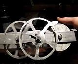
Now, I'm not intending to hijack your thread. I have some pics of an attempt at making gears.
[size=10pt][size=10pt]Sayers of Nay. Watch carefully. Science free Zone.[/size][/size]
There was no foresight into this, Just an evil eye, and heavy dose of optimism.
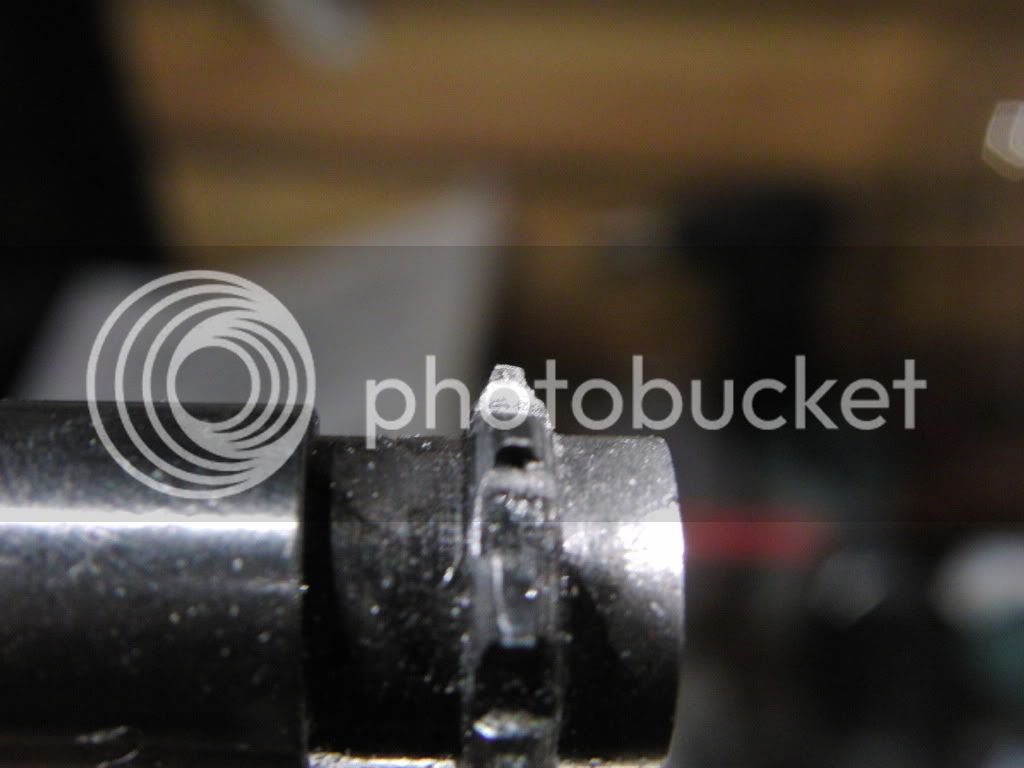
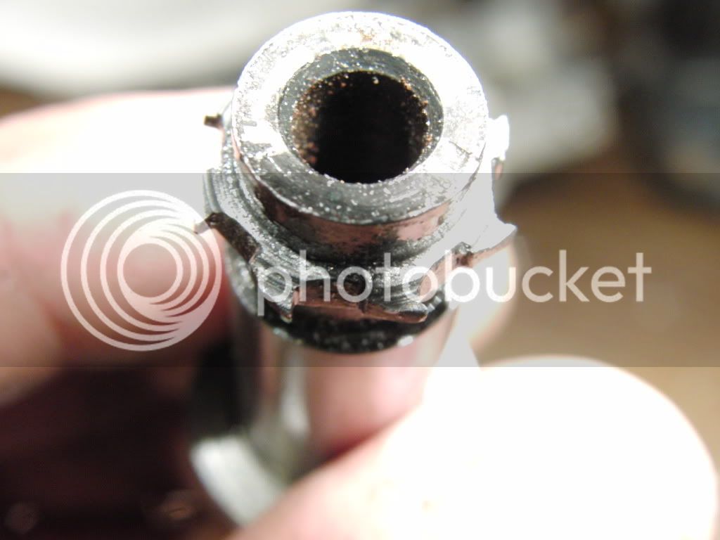
Here is the cutter I made. It is not a single point cutter, but it should apply the same. I made it out of CRS and to heat treat it I just got it really hot and then quenched it. (Pretty scientific, huh?)
Anyway, when I made the shape of the cutter, it was freehand on my mini lathe. With a close eye I was able to get a small gear like cutter. No dimensions were used. You can see that both sides of the cutter are not even the same.
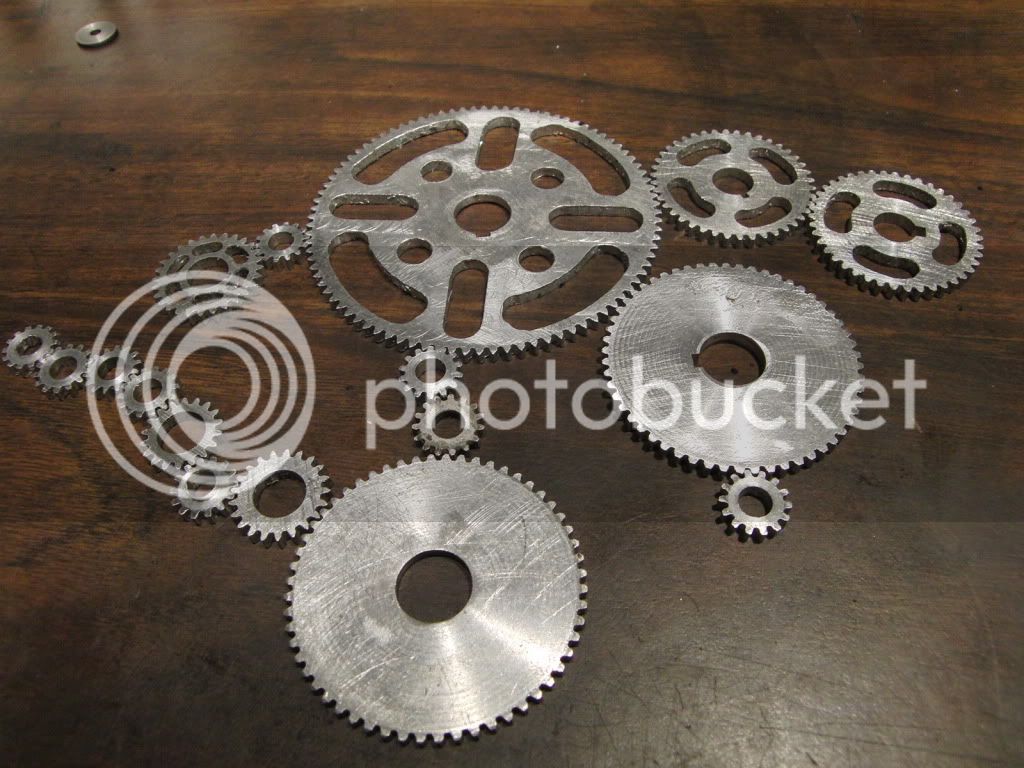
Here are some of the gears I made with them. They were all made with the same cutter. (this is impossible from what I read on the net).
The larger the gears got, the shallower I had to make the cutter cut.
I started with a one inch diameter piece, I cut one tooth, and then advanced the R/T to the nearest divisible degree until it looked good to the eye, and proceeded to cut the rest of the gear.
When it came time to figure the diameter of the gear blank, I divided 1 inch by the tooth count I had just cut, and that was my percentage for the rest of them.


OK, I know what your saying.
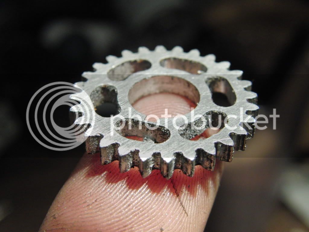
But Kel, do they mesh?
Well, you tell Me.
Don't let anyone tell you that you cant do what you have already done.
Perseverance is everything.
Kel.
[size=10pt][size=10pt]Sayers of Nay. Watch carefully. Science free Zone.[/size][/size]
There was no foresight into this, Just an evil eye, and heavy dose of optimism.
Here is the cutter I made. It is not a single point cutter, but it should apply the same. I made it out of CRS and to heat treat it I just got it really hot and then quenched it. (Pretty scientific, huh?)
Anyway, when I made the shape of the cutter, it was freehand on my mini lathe. With a close eye I was able to get a small gear like cutter. No dimensions were used. You can see that both sides of the cutter are not even the same.
Here are some of the gears I made with them. They were all made with the same cutter. (this is impossible from what I read on the net).
The larger the gears got, the shallower I had to make the cutter cut.
I started with a one inch diameter piece, I cut one tooth, and then advanced the R/T to the nearest divisible degree until it looked good to the eye, and proceeded to cut the rest of the gear.
When it came time to figure the diameter of the gear blank, I divided 1 inch by the tooth count I had just cut, and that was my percentage for the rest of them.
OK, I know what your saying.
But Kel, do they mesh?
Well, you tell Me.
Don't let anyone tell you that you cant do what you have already done.
Perseverance is everything.
Kel.
Dan Rowe
Well-Known Member
- Joined
- Feb 12, 2010
- Messages
- 594
- Reaction score
- 18
Brian,
There might have been fault in your cutter design but I think the basic aproach is sound of using the Rush Gear drawing as a basis for the design.
For some one that has Ivan Laws gear book does it have a button method solution for a #6 cutter for 17-20 teeth or does it have a seperate solution for each tooth count?
The Rush Gear drawings have a different circular segment for each of the gears made by a #6 cutter. I have started a drawing that shows all the Rush drawing data for a 24 pitch 14.5 pressure angle gear with 17, 19 and 20 teeth to complete the set cut by a #6 cutter.
If there is any interest I will post the drawing with the compareson to the generated gear teeth.
I will be starting my own post with pictures of my first failed attempt to generate a gear with the next attempt awaiting the tooling on its way to my shop.
Dan
Maryak
Well-Known Member
- Joined
- Sep 12, 2008
- Messages
- 4,990
- Reaction score
- 77
Dan Rowe said:For some one that has Ivan Laws gear book does it have a button method solution for a #6 cutter for 17-20 teeth or does it have a seperate solution for each tooth count?
Dan
Dan,
Ivan Laws book offers a set of tables for a 1 DP gear with a 20 deg and a 30 deg pressure angle.
For a #6 17-20 20 deg PA
Button Dia = 7.8"
Button centre distance = 8.7"
Infeed = 3.44"
My understanding is for other DP's divide the above by the DP e.g. for a 24 DP #6 cutter
BD = 0.325"
BCD = 0.363"
INF = 0.143"
IMHO you could have made a rack form hob and be cutting the gear before you have even finished the tool to start making the cutter and then of course you have it all to do again if there is any sort of ratio involved in your gear set.
Best Regards
Bob
- Joined
- Dec 2, 2008
- Messages
- 971
- Reaction score
- 8
Maryak said:IMHO you could have made a rack form hob and be cutting the gear before you have even finished the tool to start making the cutter and then of course you have it all to do again if there is any sort of ratio involved in your gear set.
Best Regards
Bob
Bob, what am I missing here. I think I understand that a single hob can cut all tooth counts for a given DP so to make any working pair of gears, you only need one hob. Is that correct?
For all the dissension that a circular pattern tooth face seems to draw. Is the stepped face produced by a hob, better or worse?
At my age, hardening is an unfamiliar process and if it occurs, I immediately leave the shop. But that alone keeps from taking the hob path. I know...I should learn.
My next gear making project in the very distant future will involve bevel gears on shafts that intersect at an angle greater than 90. (160 degrees actually). They will need to have a diameter somewhere between 1.5" and 2.5". The tooth count is not critical as they will be the same. Is it possible to make this kind of gear using a hob?
This is not a casual question but is an actual project that I am thinking about when I need an escape from the donkey. Your opinions are highly regarded.
Jerry
- Joined
- Jul 16, 2007
- Messages
- 2,987
- Reaction score
- 1,056
I'd like to comment on a couple of things as I am following this thread.
Kel, if you made your cutter from CRS you can't heat and quench it to make it hard. It doesn't have enough carbon in it. You can do that with drill rod. With CRS you have to carburize it, in other words you have to heat it and apply a carburizing agent on it then heat and quench it. The cutter will then be case hardened but not through hardened.
Jerry, if you make a cutter with a rack form to the teeth you can in fact cut any amount of gear teeth with it. The catch is that as the gear blank is rotated the cutter has to be advanced to follow the circular dimension of the pitch diameter.
Bevel gear cutting is not the same as spur gear cutting for the fact that the tooth needs a parallel profile and you can't do this with one pass. To do this the blank needs to be rotated to some degree and then the cutter cuts one side of one tooth. After that pass the blank needs to be rotated to the other side of the tooth, the cutter offset from center and then a second pass is made.
And no, it can't be done with a hob.
gbritnell
Dan Rowe
Well-Known Member
- Joined
- Feb 12, 2010
- Messages
- 594
- Reaction score
- 18
Bob,
Many thanks for the reply. I finished the drawings of the Rush gears for the #6 cutter they look like the 18 tooth drawing. I will line weight then and post then soon.
Jerry,
Now you have my interest as bevel gears are my main objective because I am a Shay fan. I think the best type of gear for your project would be a parallel depth bevel gear. They are much simpler to make and the design of them is covered in "Gear Design Simplified" . This is also covered in Ivan Law's gear book as I have read it on the web.
I do not believe a parallel depth bevel gear can be cut with a hob but a normal spur gear cutter can be used so the same method you used to grind your gear cutters with the Rush drawings could be used. Heck one of the ones you already made might work fine.
I know that a proper bevel gear can not be cut with a hob, a Gleason machine is what is used for modern bevel gears.
Dan
Brian, it comes as no surprise to me that the thread has "taken on a life of its own" as you say.
You embarked upon an exercise of learning, you achieved your goals while conceding that there are better ways of producing the goal and that "you probably wouldnt do it this way again"..... I thought your thread was open, clear and honest.
IMO the reason the thread has taken off was simply because of the reaction to your post, less than supportive I would have thought... something you simply dont find here on HMEM... consequently your friends here have taken a little 'umbrage', on your behalf of course.
So please dont be surprised, you are highly regarded here, and deservedly so.
Rob
Maryak
Well-Known Member
- Joined
- Sep 12, 2008
- Messages
- 4,990
- Reaction score
- 77
Jerry,
I agree with George and Dan. ;D
The only way I know to make bevel gears using a milling machine is to make "Parallel" bevel gears using the appropriate DP cutter or your single point flycutter.
Here is a crap 0 cad

As you can see , it takes a minimum of 3 passes to cut a gear, the initial through the centre cut and then the left and right offsets, with the tool passing through the original cut at the minor diameter. One other vital thing is that all calculations for this are done using the smaller or inner diameter.
Hope this helps reveling in beveling. :")
Best Regards
Bob
I agree with George and Dan. ;D
The only way I know to make bevel gears using a milling machine is to make "Parallel" bevel gears using the appropriate DP cutter or your single point flycutter.
Here is a crap 0 cad
As you can see , it takes a minimum of 3 passes to cut a gear, the initial through the centre cut and then the left and right offsets, with the tool passing through the original cut at the minor diameter. One other vital thing is that all calculations for this are done using the smaller or inner diameter.
Hope this helps reveling in beveling. :
Best Regards
Bob
- Joined
- Dec 2, 2008
- Messages
- 971
- Reaction score
- 8
Dan
I just got my new issue of Home Shop Machinist and the cover picture and feature tease says "Shop Made Bevel Gears". The article was a disappointment to me. It was mainly a book review and to get the whole story you must buy "Building the Climax" by Kozo Hiraoka. There was some discussion pitch considerations on bevel gears and a tiny description on bevel gears vs skew bevel gears. There was no discussion at all on tool path and offset.
It whet my appetite and left me hungry so I have downloaded a solid model of a miter gear from the Rush Gear site and I have read all that I could find re bevel gears on the net. I think that I have worked out the geometry for a tapered height, radius faced, tooth form and the tool path required to cut it with a single point cutter. At least for 90 degree miter gears. I think I can translate the geometry to the 160 degree configuration that I need. When I get to it, I think it will be possible to cut in a single pass.
The gears will not rotate, they will nutate and be used to prevent rotation in a wobble plate engine. It is not a new idea. It has been used before and only recently came within my ability scope (I hope).
Are you building a Shay? Have you reached the point of cutting the gears? I would like to see it.
Jerry
- Joined
- Dec 2, 2008
- Messages
- 971
- Reaction score
- 8
Bob,
We were posting at the same time so I got head of your answer. I have seen that recommendation (parallel form) teeth before. And I have seen Gleason machines in operation. From what little I know about Gleason machines, I thought that their primary virtue was cutting curved tooth forms as in spiral bevel gears and hypoid gears.
If that is true, what is the right machine to cut a proper bevel gears, a shaper?
Jerry
Dan Rowe
Well-Known Member
- Joined
- Feb 12, 2010
- Messages
- 594
- Reaction score
- 18
Jerry,
I have all the geared engine books by Kozo so the article was interesting to me, but it really requires the Climax book for complete understanding. That gear is a skew parallel depth gear where the two shafts are not in the same plane. The only place I have ever seen detailed information of that type of gear is the Climax book by Kozo.
Nutating bevel gears wow what fun.
There was a method to cut aproximate bevel gears with thin versions of standard spur gear cutters. The cutter curve was set for the big end and was thin enough to pass through the small end. I have seen these cutters on ebay from time to time. The method requires the small ends to be filed to correct the curve error.
I am building a Shay in two scales. I have been writting a series on the 7/8ths scale 10 ton Shay for G1 track in "Steam in the Garden" The prints are 7/8 scale versions of the Lima Locomotive Works drawings. The series started with issue #100 with a double fold of both sides and end views in 7/8ths scale.
I have not cut a bevel gear yet but I hope to soon.
The drawings of the Rush gears for 17, 19 & 20 teeth look very similar to the 18 tooth version. The red tooth profile is the generated profile in the single tooth inset.
The proper name of a gear shaper to generate bevel gears is a Bilgram machine. I have a bit of a collection of information on these machines and can start a thread on them.
Dan
.jpg")
.jpg")
.jpg")
I have all the geared engine books by Kozo so the article was interesting to me, but it really requires the Climax book for complete understanding. That gear is a skew parallel depth gear where the two shafts are not in the same plane. The only place I have ever seen detailed information of that type of gear is the Climax book by Kozo.
Nutating bevel gears wow what fun.
There was a method to cut aproximate bevel gears with thin versions of standard spur gear cutters. The cutter curve was set for the big end and was thin enough to pass through the small end. I have seen these cutters on ebay from time to time. The method requires the small ends to be filed to correct the curve error.
I am building a Shay in two scales. I have been writting a series on the 7/8ths scale 10 ton Shay for G1 track in "Steam in the Garden" The prints are 7/8 scale versions of the Lima Locomotive Works drawings. The series started with issue #100 with a double fold of both sides and end views in 7/8ths scale.
I have not cut a bevel gear yet but I hope to soon.
The drawings of the Rush gears for 17, 19 & 20 teeth look very similar to the 18 tooth version. The red tooth profile is the generated profile in the single tooth inset.
The proper name of a gear shaper to generate bevel gears is a Bilgram machine. I have a bit of a collection of information on these machines and can start a thread on them.
Dan
Maryak
Well-Known Member
- Joined
- Sep 12, 2008
- Messages
- 4,990
- Reaction score
- 77
Jerry,
One thing I forgot to answer is yes a hob will cut a gear with any no. of teeth for the given DP/Module. The small ridges formed using the hob are soon worn away as the gear works, but IMHO they are noisier than a gear made with a DP cutter. A bit of heavier oil sorts that out.
Because the tooth form as well as the depth of a "True" bevel gear varies along its' length. A generator such as the Gleason you refer to gives the correct tooth profile. A gear so generated could then be used a the cutting tool on a gear shaper.
Ah what a tangled web we weave.
Best Regards
Bob
Kozo published a great way to make bevel gears, spiral bevel gears, and spur gears in the lathe as part of one of his logging locomotives. Home Shop machinist recently republish some of this work. Even shows, as only Kozo can, how to make the fixtures and gear cutters in your own shop....Worth every penny.
Dave
Dave
Dan Rowe
Well-Known Member
- Joined
- Feb 12, 2010
- Messages
- 594
- Reaction score
- 18
steamer said:Kozo published a great way to make spiral bevel gears,
Dave
Dave,
The Climax gears only look a bit like spiral gears they are actually straight tooth skew bevel gears with 90 degreee shafts not in the same plane. Kozo had to work out how to make this very rare type os bevel gear and that is an apendex to the Climax book. And yes the books are worth every penny. Some of the technique I learned from Kozo I was able to use in full size practice as a Marine Engineer.
Dan
Thanks for the response Dan.
Your correct to the terminology...the hour is late and I've been going since 5am
I found a spread sheet on the net that did the Kozo calculations for the bevel gears.
I think it was from the Yahoo gear cutting group.....I'll look.
Steam or Diesel?
Dave
PS Uploaded a Google book on Spur and Bevel Gears.....still looking for the spreadsheet....I know I saw it somewhere...