
You are using an out of date browser. It may not display this or other websites correctly.
You should upgrade or use an alternative browser.
You should upgrade or use an alternative browser.
Crusader .60s (x2)
- Thread starter wareagle
- Start date


Help Support Home Model Engine Machinist Forum:
This site may earn a commission from merchant affiliate
links, including eBay, Amazon, and others.
wareagle, The ringed piston was just harder to get good compression with. As well as more trouble to make. I was just trying for a lighter piston for more rpm with it. I made the wrist pin from titanium as well  .
.
DICKEYBIRD, Boy it's been a while since I made those parts, but the cyl head is shown in it's as machined state with a little hand deburring. A Slotting saw used for the fins with wd40 as lube. I can't remember what I made it out of though. It might be 2024 rather than 6061.
Steve
.DICKEYBIRD, Boy it's been a while since I made those parts, but the cyl head is shown in it's as machined state with a little hand deburring. A Slotting saw used for the fins with wd40 as lube. I can't remember what I made it out of though. It might be 2024 rather than 6061.
Steve
Maryak said:W/E,
From what I know already - YOU"LL BOLT IT IN :
Regards
Bob
Thanks, Bob. I'll certainly give 'er hell!
S_J_H said:wareagle, The ringed piston was just harder to get good compression with. As well as more trouble to make. I was just trying for a lighter piston for more rpm with it. I made the wrist pin from titanium as well
Thanks for that bit! For the first go 'round, I was planning on sticking with the plan as is, but had thought of the same mod. I guess that saves me the time! Over the past few days as I have been boxed up, I have thought of adapting this engine for ball bearings on the main and rod journals. Maybe raising the compression ratio some as well. Probably won't and will let it be in the end. I'll be happy with a smooth runner and am getting anxious on starting the next project.
More to come soon!
Well, I hit it again this evening. Made some headway on a couple of the tooling fixtures. I needed one to support the tail end of the crank shaft and while I was at it, I went on and made a couple of the others that will be needed. No pictures tonight...
I did a little studing of the plans this evening, and I am having a concern on the layout of the ports in the piston and cylinder. I looked and did a little bit of figuring, but it looks like one of the ports will be in the wrong location slightly. I think I am going to lay it out in CAD (because I am lazy) and double check things before I make any of those cuts. I'd hate to get towards the end of this and find out that a dimension was wrong and I had to remake the cylinder!
Hopefully if all goes well, I will get a temporary pass to make some more chips this weekend. I'd really like to finsih the crankshaft and get on with some other things. Actually, with the crankshaft, all I would need is the piston and connecting rod, and then I could actually measure the proposed port locations and make sure that everything is falling where it should.
Until then.....
Maryak
Well-Known Member
- Joined
- Sep 12, 2008
- Messages
- 4,990
- Reaction score
- 77
W/E
Try Rons site:
http://www.modelenginenews.org/
under resources
design centre
are some calculators which will produce a timing diagram for you.
Best Regards
Bob
Try Rons site:
http://www.modelenginenews.org/
under resources
design centre
are some calculators which will produce a timing diagram for you.
Best Regards
Bob
Well, I made it to the shop and actually made some progress for a change.
The evening started off on a bit of a sour note... The crankshaft that I was working on was inadvertently knocked off of the bench and it landed on the rod journal. Running an indicator confirmed the fears; the crank is bent. Along the crankshaft lines, I did manage to finish the fixture that will support he back of the crankshaft during the machining operations on the lathe.
So, on to other things. As I have said before, this engine is fixture intensive if you follow the build article. I am building the fixtures for the purposes of building another Crusader in the future. It's a pain right now, but in the end I think the trouble will be worth it.
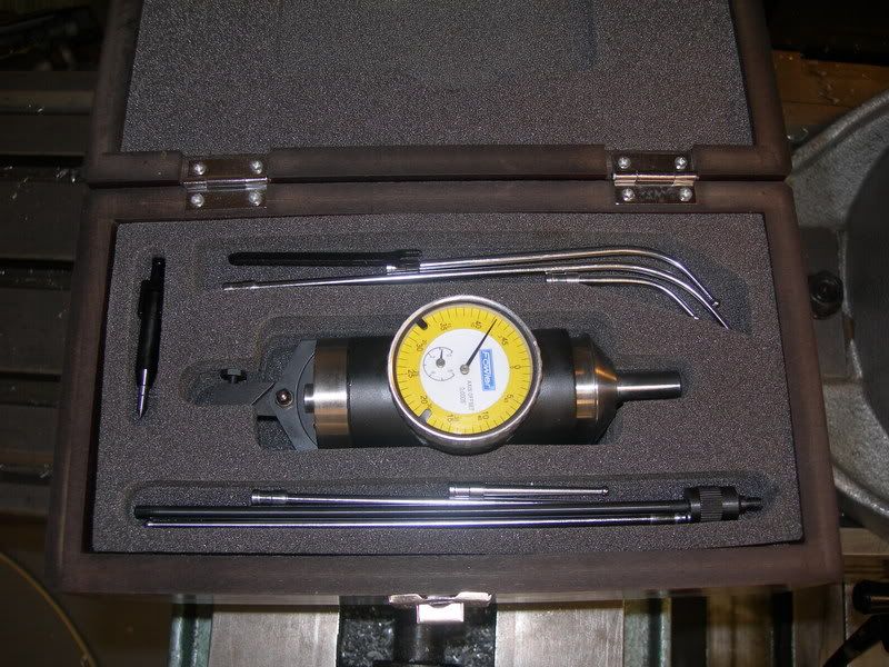
So, I started by drilling the fixture that locates the holes for the head and cylinder. I located the rotary table with my nifty little coax indicator that Casper the Friendly Ghost left for me. See this topic for details. I must say, this thing is the cat's meow! I had the RT located dead on in about 60 seconds.
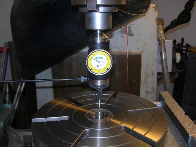
After locating the RT, I set the jig on a couple of pieces of brass stock for drilling clearance and located the jig to center. Once done, the radius dimension was dialed in and six holes were drilled evenly apart.
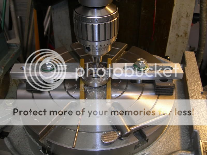
NOTE: The method used to secure the jig to the RT looks spooky, but the piece was solid enough to drill holes safely. I wouldn't try to do anything beyond drilling holes with this setup. When securing a work piece, be sure that the method secures the work piece to withstand the forces that will be applied during the operations! Loss of tooling, workpieces, both or personal injury are hazards that are present when a work holding method fails.
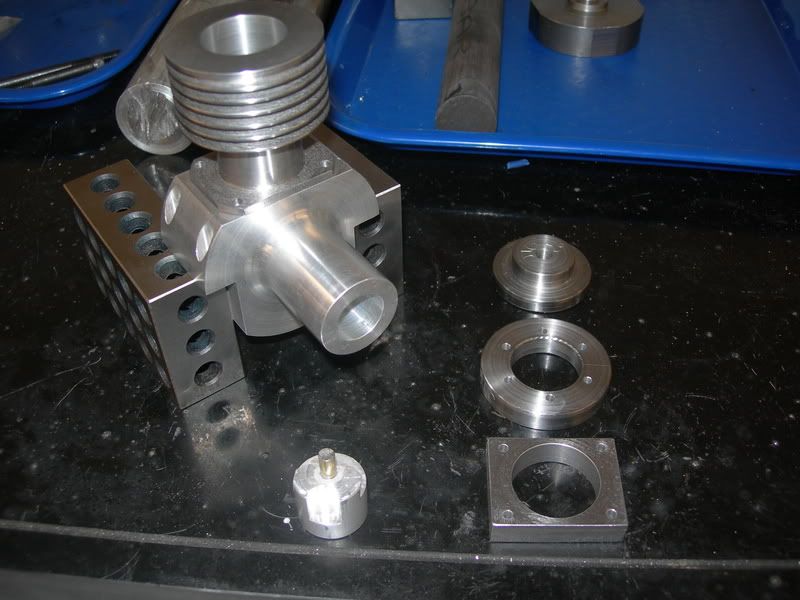
After that, the jig for the cylinder and crankcase bolts was profiled and the hole was bored. Then the holes were drilled in the jig and everything was deburred. I then mounted it to the cylinder and drilled the holes for the bolts. The flange that meets the crankcase was profiled. Then came another round of careful deburring of the cylinder flange and holes. Sorry, no pics of this.
This is where the night left off. The cylinder and crankcase are sitting happily on the 1-2-3 blocks, and the jigs/fixtures that were machined this evening are placed around the on the bench.
The next step is to finish the crankcase which will involve cutting the fins on the bottom (for bling purposes only) and turning the bushing and pressing it in the crankcase. Beyond that, the CC will be ready for the remaining parts that are dying to be dug out of the bar stock laying about in the shop. Next in line will be the crankshaft. That will obviously be rework, but that's okay... I need the practice.
The evening started off on a bit of a sour note... The crankshaft that I was working on was inadvertently knocked off of the bench and it landed on the rod journal. Running an indicator confirmed the fears; the crank is bent.
Along the crankshaft lines, I did manage to finish the fixture that will support he back of the crankshaft during the machining operations on the lathe.So, on to other things. As I have said before, this engine is fixture intensive if you follow the build article. I am building the fixtures for the purposes of building another Crusader in the future. It's a pain right now, but in the end I think the trouble will be worth it.
So, I started by drilling the fixture that locates the holes for the head and cylinder. I located the rotary table with my nifty little coax indicator that Casper the Friendly Ghost left for me. See this topic for details. I must say, this thing is the cat's meow! I had the RT located dead on in about 60 seconds.
After locating the RT, I set the jig on a couple of pieces of brass stock for drilling clearance and located the jig to center. Once done, the radius dimension was dialed in and six holes were drilled evenly apart.
NOTE: The method used to secure the jig to the RT looks spooky, but the piece was solid enough to drill holes safely. I wouldn't try to do anything beyond drilling holes with this setup. When securing a work piece, be sure that the method secures the work piece to withstand the forces that will be applied during the operations! Loss of tooling, workpieces, both or personal injury are hazards that are present when a work holding method fails.
After that, the jig for the cylinder and crankcase bolts was profiled and the hole was bored. Then the holes were drilled in the jig and everything was deburred. I then mounted it to the cylinder and drilled the holes for the bolts. The flange that meets the crankcase was profiled. Then came another round of careful deburring of the cylinder flange and holes. Sorry, no pics of this.
This is where the night left off. The cylinder and crankcase are sitting happily on the 1-2-3 blocks, and the jigs/fixtures that were machined this evening are placed around the on the bench.
The next step is to finish the crankcase which will involve cutting the fins on the bottom (for bling purposes only) and turning the bushing and pressing it in the crankcase. Beyond that, the CC will be ready for the remaining parts that are dying to be dug out of the bar stock laying about in the shop. Next in line will be the crankshaft. That will obviously be rework, but that's okay... I need the practice.
Maryak said:Bugger
Yeah... Ya win some, ya lose some, and some are a draw! I figured there would be a part or two that would be required to make from scratch. It is just lost time and a little money in materials, and usually on the second go things go smoother and the part is better in the end. With this being the crank, I don't mind too much. I'll just make it better than the first! 8)
Maryak said:Did you sort out your timing/porting problem ???
I did... Until I trashed the crank. Once I get the new crank made, I will measure it and will layout the ports with the new dimensions. The site link you shared has helped immensely. :bow: The published timing was off by just a slight bit, but the first crank had about .005" more stroke than the plans show. Not exactly sure where the discrepancy is.... ???
The other piece to this puzzle is the cylinder deck height. I think the author was allowing a little for a gasket to be installed. My cylinder should seal around the spigot hole, thought I am wandering about the expansion of the aluminum loosening that up a bit when the engine gets to operating temperature. A little high temp gasket sealer will be my plan B.
My plan of attack is to get the rotating assembly finished and put everything in place prior to cutting the ports. I may have to make two pistons to accomplish this because I want to lap the cylinder after the silver brazing has been completed. Once everything is together and measured, I can lay it out in CAD and verify the port locations and dimensions prior to making those cuts. I'm not sure why the little hair is standing up on the back of my neck regarding the build article and the published port locations, but I want to make certain that they are correct!!
I appreciate the feedback and support!!
Well, I finally found some time to make it to the shop. This thing called work really intrudes on one's play time! ;D
My plan of attack was to machine the bushing for the crankshaft and press it into the crank case. Afterward, I would machine the crankshaft, and then drill and tap the holes in the crank case. The crankshaft is, in my opinion, the most complex part to be made for the engine, so I had planned on that taking a period of time to accomplish.
_________________________________________________
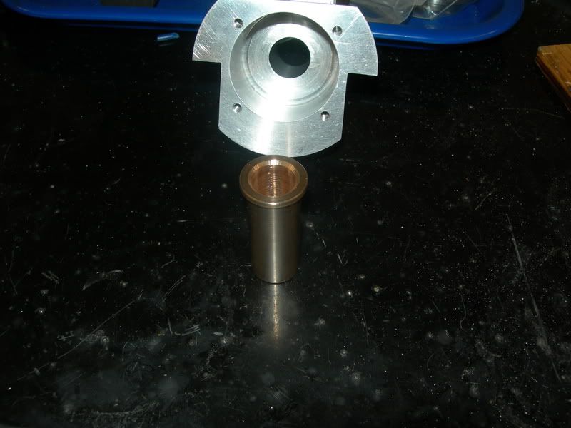
The bushing is pretty straight forward. The inside diameter is .500" and the outside diameter is .626 -.627" for a press fit in the crankcase. There is a trust face of .750" diameter on one end of the bushing, and it is .062" in length. I left mine at .075" so I could get the end play correct. I'll chuck the crankcase in the lathe when the time comes, and make the final cut on the trust face. More on this brilliant idea in a bit...
Here's is the bushing and crankcase ready for the press. I added a little heat to aid in the pressing operation by putting the crankcase in the over at 400 degrees for about 15 minutes prior to assembly. No problems with this operation, and the bushing is now installed.
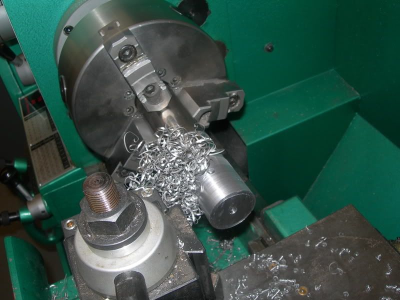
Next on the list to do is the second attempt at the crankshaft. I chucked up a piece of bar stock and started turning the crankshaft down. The main bearing journal is .499 - .500" in diameter. The overall diameter of the throw is 1.375" diameter. I turned the nose of the crank down and set up a makeshift tool post grinder to take it to dimension.
Turning the nose of the crank down to dimension.
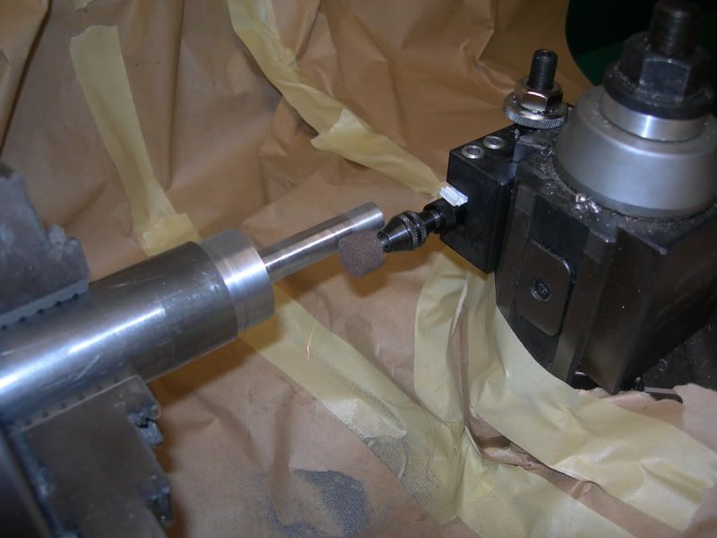
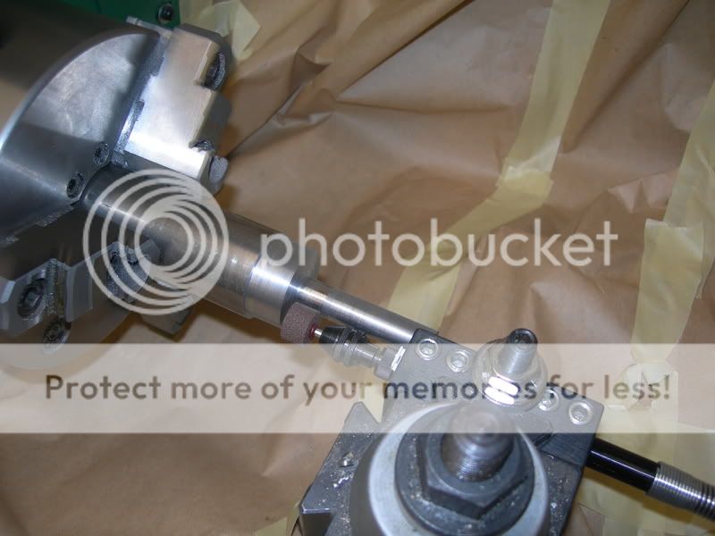
The makeshift tool post grinder... I took a Dremel tool and mounted the flexible shaft to a QCTP. I then chucked up a grinding bit in the collet and went to town. I saved .005" so that the shaft could be ground to dimension, and the Dremel tool worked well for this. It doesn't have enough torque to take more than .001 - .0015" off at a pass, but it got the job done. Note that there is butcher paper protecting the ways of the lathe. The last thing I wanted was to have grinding grit where grinding grit isn't supposed to be!!
So, we're cookin' with grease now. The shaft is ground to dimension, and turned out well for the improvised tool post grinder. The next thing is to cut a .030" groove .350" from the nose of the crank, and turn the end of the nose down to .437". The next step is to drill and tap the center of the nose with a 1/4 x 28 thread about .625" deep. No problems with these operations, and the crank is now cut from the piece of bar stock.
The crank along side the crank case.
And a test fit of the crankshaft in the bushing/crankcase.
The crankshaft is a nice fit and turns with ease. So all is going well. Now for the fun part, machining the business end of the crankshaft. The design calls for a connecting rod journal of .375" diameter to be turned offset .437" of the center line of the crankshaft. There is also a counterweight that is integral to the crank as well, and a subsequent operation on the mill will remove more of the material fro balancing.
Now the lathe is changed for the three jaw to four jaw chuck, and the back side of the crank is laid out and scribed for reference. The dimensions are measured against the drawing, and that's when the it was realized that the saw took to much material off of the end of the crankshaft. :wall: After some choice words my little boy likely would repeat if he was in ear shot, I looked into where the problem came from.
 It was a simple error in arithmetic. I had played it safe (so I thought) by adding a cushion of material on the end of the crankshaft, but the extra was of no use, the shaft was too short by .015". It's my own fault... Cut once, then measure twice!


So now that I have theoretically lost an afternoon in the shop, I have taken the time to sit down on go through my steps again, and I have realized that my plan of adjusting the end play by turning the thrust face of the bushing down won't work out, because the crankshaft will then need to have the nose length changed.
 I have also come to the conclusion that I will write out my steps and measurements in a machining sequence prior to going for a third go at the crankshaft.
At this point I am too irritated to do anything else, so I call it a night. Stay tuned for Crankshaft, Part III.
My plan of attack was to machine the bushing for the crankshaft and press it into the crank case. Afterward, I would machine the crankshaft, and then drill and tap the holes in the crank case. The crankshaft is, in my opinion, the most complex part to be made for the engine, so I had planned on that taking a period of time to accomplish.
_________________________________________________
The bushing is pretty straight forward. The inside diameter is .500" and the outside diameter is .626 -.627" for a press fit in the crankcase. There is a trust face of .750" diameter on one end of the bushing, and it is .062" in length. I left mine at .075" so I could get the end play correct. I'll chuck the crankcase in the lathe when the time comes, and make the final cut on the trust face. More on this brilliant idea in a bit...
Here's is the bushing and crankcase ready for the press. I added a little heat to aid in the pressing operation by putting the crankcase in the over at 400 degrees for about 15 minutes prior to assembly. No problems with this operation, and the bushing is now installed.
Next on the list to do is the second attempt at the crankshaft. I chucked up a piece of bar stock and started turning the crankshaft down. The main bearing journal is .499 - .500" in diameter. The overall diameter of the throw is 1.375" diameter. I turned the nose of the crank down and set up a makeshift tool post grinder to take it to dimension.
Turning the nose of the crank down to dimension.
The makeshift tool post grinder... I took a Dremel tool and mounted the flexible shaft to a QCTP. I then chucked up a grinding bit in the collet and went to town. I saved .005" so that the shaft could be ground to dimension, and the Dremel tool worked well for this. It doesn't have enough torque to take more than .001 - .0015" off at a pass, but it got the job done. Note that there is butcher paper protecting the ways of the lathe. The last thing I wanted was to have grinding grit where grinding grit isn't supposed to be!!
So, we're cookin' with grease now. The shaft is ground to dimension, and turned out well for the improvised tool post grinder. The next thing is to cut a .030" groove .350" from the nose of the crank, and turn the end of the nose down to .437". The next step is to drill and tap the center of the nose with a 1/4 x 28 thread about .625" deep. No problems with these operations, and the crank is now cut from the piece of bar stock.
The crank along side the crank case.
And a test fit of the crankshaft in the bushing/crankcase.
The crankshaft is a nice fit and turns with ease. So all is going well. Now for the fun part, machining the business end of the crankshaft. The design calls for a connecting rod journal of .375" diameter to be turned offset .437" of the center line of the crankshaft. There is also a counterweight that is integral to the crank as well, and a subsequent operation on the mill will remove more of the material fro balancing.
Now the lathe is changed for the three jaw to four jaw chuck, and the back side of the crank is laid out and scribed for reference. The dimensions are measured against the drawing, and that's when the it was realized that the saw took to much material off of the end of the crankshaft. :wall: After some choice words my little boy likely would repeat if he was in ear shot, I looked into where the problem came from.
So now that I have theoretically lost an afternoon in the shop, I have taken the time to sit down on go through my steps again, and I have realized that my plan of adjusting the end play by turning the thrust face of the bushing down won't work out, because the crankshaft will then need to have the nose length changed.
At this point I am too irritated to do anything else, so I call it a night. Stay tuned for Crankshaft, Part III.
Maryak
Well-Known Member
- Joined
- Sep 12, 2008
- Messages
- 4,990
- Reaction score
- 77
W/E
DOUBLE BUGGER :'( :'(
Remember the old adage 3rd time lucky.
I'll bet you had something else on your mind even if it was subconscious.
Hang in there buddy I'm on your side and I really like your improvised toolpost grinder.
Best Regards
Bob
DOUBLE BUGGER :'( :'(
Remember the old adage 3rd time lucky.
I'll bet you had something else on your mind even if it was subconscious.
Hang in there buddy I'm on your side and I really like your improvised toolpost grinder.
Best Regards
Bob
dsquire
Well-Known Member
- Joined
- Mar 18, 2008
- Messages
- 980
- Reaction score
- 15
wareagle
Too bad about the tough luck on the cranks. I know exactly how you feel, I've been there. You try so hard the second time to make it better and it comes back to bite you some place else. Just remember the third times a charm. Got my fingers crossed for you.
Glad to see that your feeling bertter.
Cheers
Don
Metal Mickey
Well-Known Member
- Joined
- Jul 5, 2008
- Messages
- 612
- Reaction score
- 6
:bow: :bow: :bow:
I am very impressed and can see you are a quality engineer. I like the grinding solution in particular. And the protection method of the lathe. I will store that away for the future thats for sure, so thanks for that.
Mike
I am very impressed and can see you are a quality engineer. I like the grinding solution in particular. And the protection method of the lathe. I will store that away for the future thats for sure, so thanks for that.
Mike
Bob, Mike, and Don, thanks for the kind comments! They are much appreciated.
I did get out to the shop for a short period of time, and I did make a start on crankshaft #3. About the time I faced the end off, tapped and threaded the hole for the prop stud, the phone rang and I had to take care of the work thing. :
It's a bummer when you get a small tast of something sweet, only to have the spoon abruptly pulled from your mouth! Oh well, it's still progress even as little as it is.
Hopefully I'll have more to share in the next day or so!
Brass_Machine
Well-Known Member
- Joined
- Aug 28, 2007
- Messages
- 1,314
- Reaction score
- 7
Been awhile since I looked at this post... it was barely 1 page. The crankcase looks awesome WE. Sorry to hear about the cranks. You will knock it out this time. I have a huge pile of 1st 2nd 3rd all the way up of parts attempts. ;D
Eric
Eric
Crankshaft Part III
All right, so I made it out to the shop today and made some progress on the little beast. After the last episode of cutting too much off of the crankshaft, I decided that I would do my homework and have a procedure written down and follow it during the next attempt (this one). I also found a couple of errors in my approach that would have bit me later. PPP = PPP P_$$ Poor Planning = P_$$ Poor Performance
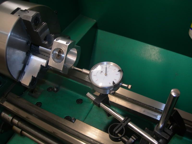
I checked the plans against the actual measurements on the crankcase and bushing. What I discovered is that the thrust face needed to have .032" taken off. I chucked the crankcase in the lathe and checked the back for run-out. First time was a charm! Cutting the bushing was straight forward, and it wound up dead on.
Checking the run-out on the crankcase with a dial indicator
Next up is machining a fixture to hold the crank for machining the business end. Maryak, I ripped this idea from your project! Hope ya don't mind! The reason I chose to do this was to protect the newly polished main journal. My first thought was to use the four jaw to get the offset, but after seeing the way Maryak did his crank, I decided to have a go at it myself. The fixture only took about ten minutes to bang out, and I was on my way.
To make the fixture, I chucked up a piece of 1.750" aluminum bar stock about 4" long and faced the end and center drilled a locating hole. I flipped it and faced the opposite side. The piece was taken to the mill where it was squared up in the vise and the center was located. I then move the table the distance needed (radius of the stroke) and drilled/reamed a hole for the crankshaft main journal to be inserted. I then drilled a 1/4" opposite of the center-line through the part to relieve the stress from flexing during clamping. A slitting saw finished the fixture up after flipping it on its side in the vise.
In the three jaw chuck, it is hard to have repeatability due to the run out they typically have. To reduce the problem, I have identified each of the jaws on my three jaw with a different color on each. If I have a need to remove a part and put it back for further operations, I just make the part with the same colors at each jaw and then when it goes back I can have it clocked in the chuck as it was previously. In my experience with my chuck, I get about .001" run-out when doing this. The crank fixture was identified this way and I did a test run on the previous crank we'll call Shorty. I chucked Shorty up and did a cut to make sure the fixture would indeed hold the crank solidly,and also pulled it out and chucked it back up several times to verify the run-out. It was either dead on or at the worst .001" TIR.
This might be a trick to save some time with changing between the three and four jaw chucks. Keep in mind that it doesn't eliminate the run-out issue, it just keeps it close. If your task requires a high degree of precision, then I suggest you use the four jaw for those purposes. Use this trick at your own risk!!
The trial run on the crank fixture using Shorty
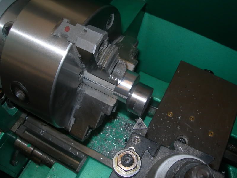
Next is making the infamous crankshaft. Fortunately, I have plenty of material and should a fourth, fifth, or even sixth attempt need to be taken at getting a good crankshaft, I wouldn't have to buy anything. And off we go. I chucked up a piece of bar stock in the three jaw and faced the end and center drilled the nose. I went ahead and drilled/tapped the hole (1/4 x 24) while I was there.
Next I started the mass removal of metal. It took moderate cuts until I got about half way there, then I progressively used lighter and lighter cuts as I approached the final dimension. This was to avoid any chance of warping the crank from too much force from the cutting tool and the reduce the amount of heat being generated in the part. I was concerned about a potential for warp-age, so I stopped about .050" from the final dimension and let it cool off for a few hours.
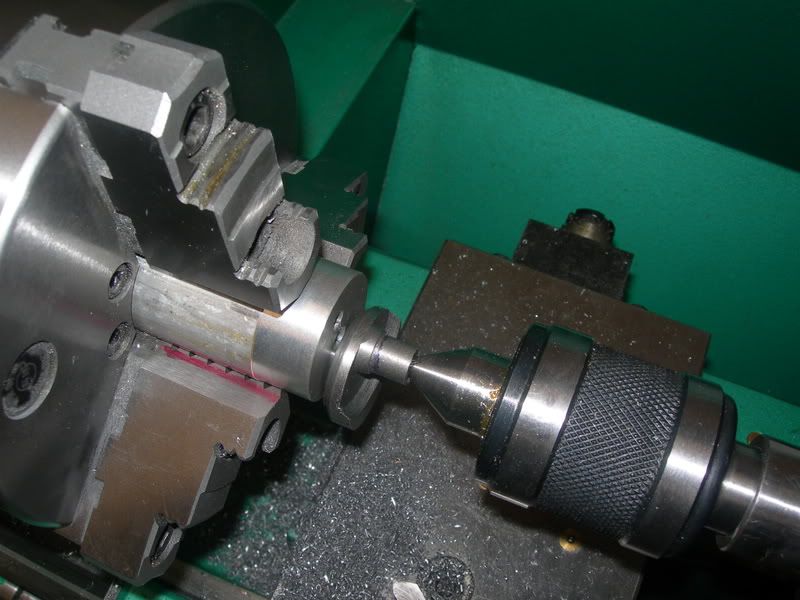
Turning the nose of the crankshaft
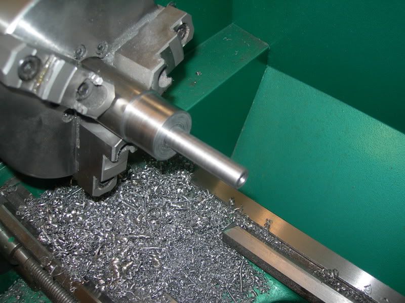
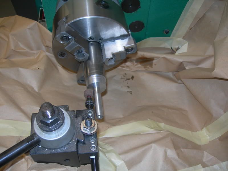
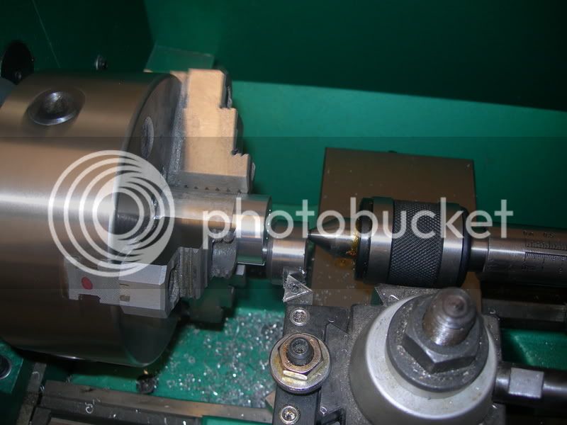
After the part cooled off, I finished the cut to .002" oversize. I employed the hillbilly tool post grinder to take the part to the final dimension (actually about .0002" oversize). I then polished the main journal with 800 grit Emory cloth and oil.
The hillbilly tool post grinder
This has worked out pretty well for getting a good finish on a part. A couple of things to keep in mind if you try it... Make sure you dress your stone before grinding the part. They are not very concentric! And don't try to take a heavy cut. The shaft on the bit will flex and the Dremel tool doesn't have enough torque to turn the stone with a heavy bite. I have found that .001" - .0015" is about all it wants. And protect your machine! Butcher paper is what I use.
So far so good. I was at the same place last time when things went awry! : The next step is to cut the stock off and put the nose in the fixture for the next operations. And, this time, I got it right!
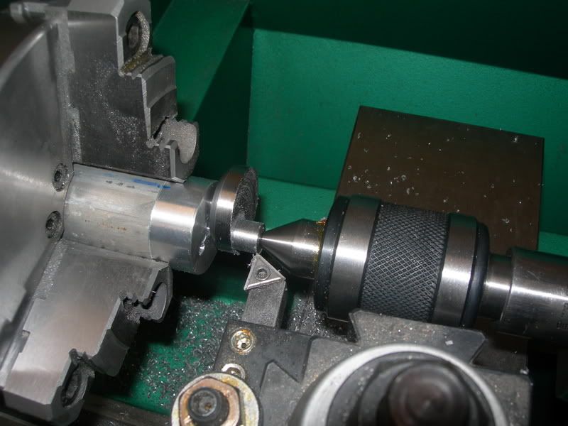
The crank was placed in the fixture and chucked up in the lathe. I carefully faced it off and then drilled a locating hole for the live center. The business end was then roughed out to size, but this was a slow go. I didn't want to take chances of the crank moving within the fixture and making my next post Crankshaft IV. So light cuts were the order and I eased it down close to the dimension.
The crank in the fixture backed up with the live center
She's slowly getting there
Now we're real close, just need to do some final shape cuts and finish it up
And then Mr. Murphy makes his appearance... As I am making my shaping cuts, I notice that the live center is dancing very slightly back and forth. At this point I know the the crank has moved in the fixture. So I stop and take a break before exploding into a ginormous mushroom cloud. As I was contemplating which one of you were about to be the recipients of a mill and lathe, the "You Dumb-ass" fairy popped in my head... All I had to do is loosen the chuck, then relocate the crank pin back to center and all would be well.
That's exactly what I did and moved on. I didn't have any more issues with movement going forward. The finish cuts were made and the rod journal was polished. I drilled the hole in the rod journal for the pin that will turn the rotary valve and verified all of the measurements. I missed the thickness of the counter weight by .001". Everything else hit dead on.
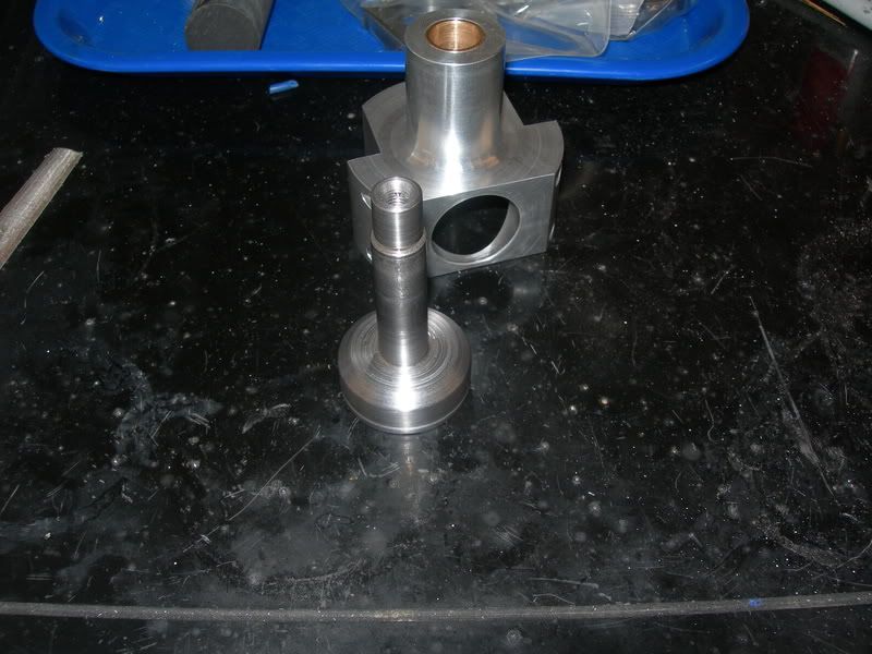
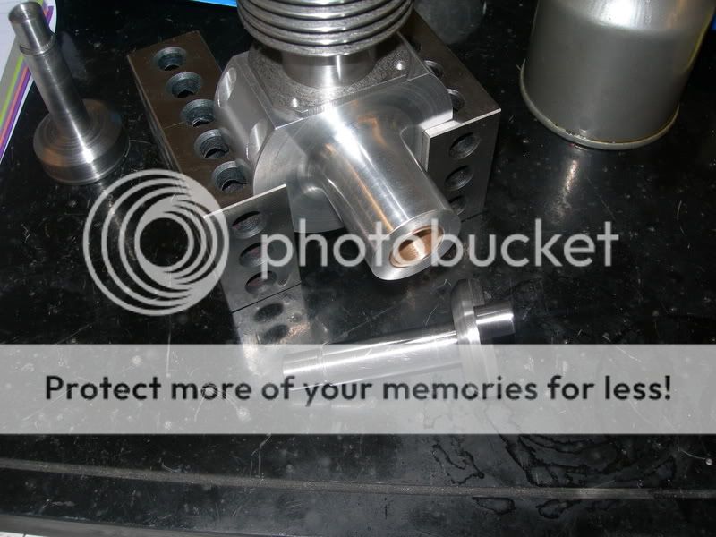
Success! Here is the crankshaft with the crankcase and cylinder
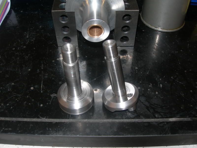
And here is the Shorty with the new crank
So that conclude this episode of Crankshaft Part III
Next up for the crankshaft will be milling the angles on the crank disk, but I believe that will wait until I get the connecting rod and piston made. I am planning on doing a proper balance job on it. And I am looking at the rod journal throw and am thinking that I will be needing to notch out the crankcase to make way for the con rod.
It doesn't look like much, but that was a day!! Everyone's support and comments are appreciated. Finishing this piece today was a milestone, and I fell like I have now made it to the top of the mountain and will have some momentum to carry through the remaining part of the project. Stay tuned!!
All right, so I made it out to the shop today and made some progress on the little beast. After the last episode of cutting too much off of the crankshaft, I decided that I would do my homework and have a procedure written down and follow it during the next attempt (this one). I also found a couple of errors in my approach that would have bit me later. PPP = PPP P_$$ Poor Planning = P_$$ Poor Performance
I checked the plans against the actual measurements on the crankcase and bushing. What I discovered is that the thrust face needed to have .032" taken off. I chucked the crankcase in the lathe and checked the back for run-out. First time was a charm! Cutting the bushing was straight forward, and it wound up dead on.
Checking the run-out on the crankcase with a dial indicator
Next up is machining a fixture to hold the crank for machining the business end. Maryak, I ripped this idea from your project! Hope ya don't mind!
The reason I chose to do this was to protect the newly polished main journal. My first thought was to use the four jaw to get the offset, but after seeing the way Maryak did his crank, I decided to have a go at it myself. The fixture only took about ten minutes to bang out, and I was on my way.To make the fixture, I chucked up a piece of 1.750" aluminum bar stock about 4" long and faced the end and center drilled a locating hole. I flipped it and faced the opposite side. The piece was taken to the mill where it was squared up in the vise and the center was located. I then move the table the distance needed (radius of the stroke) and drilled/reamed a hole for the crankshaft main journal to be inserted. I then drilled a 1/4" opposite of the center-line through the part to relieve the stress from flexing during clamping. A slitting saw finished the fixture up after flipping it on its side in the vise.
In the three jaw chuck, it is hard to have repeatability due to the run out they typically have. To reduce the problem, I have identified each of the jaws on my three jaw with a different color on each. If I have a need to remove a part and put it back for further operations, I just make the part with the same colors at each jaw and then when it goes back I can have it clocked in the chuck as it was previously. In my experience with my chuck, I get about .001" run-out when doing this. The crank fixture was identified this way and I did a test run on the previous crank we'll call Shorty. I chucked Shorty up and did a cut to make sure the fixture would indeed hold the crank solidly,and also pulled it out and chucked it back up several times to verify the run-out. It was either dead on or at the worst .001" TIR.
This might be a trick to save some time with changing between the three and four jaw chucks. Keep in mind that it doesn't eliminate the run-out issue, it just keeps it close. If your task requires a high degree of precision, then I suggest you use the four jaw for those purposes. Use this trick at your own risk!!
The trial run on the crank fixture using Shorty
Next is making the infamous crankshaft. Fortunately, I have plenty of material and should a fourth, fifth, or even sixth attempt need to be taken at getting a good crankshaft, I wouldn't have to buy anything. And off we go. I chucked up a piece of bar stock in the three jaw and faced the end and center drilled the nose. I went ahead and drilled/tapped the hole (1/4 x 24) while I was there.
Next I started the mass removal of metal. It took moderate cuts until I got about half way there, then I progressively used lighter and lighter cuts as I approached the final dimension. This was to avoid any chance of warping the crank from too much force from the cutting tool and the reduce the amount of heat being generated in the part. I was concerned about a potential for warp-age, so I stopped about .050" from the final dimension and let it cool off for a few hours.
Turning the nose of the crankshaft
After the part cooled off, I finished the cut to .002" oversize. I employed the hillbilly tool post grinder to take the part to the final dimension (actually about .0002" oversize). I then polished the main journal with 800 grit Emory cloth and oil.
The hillbilly tool post grinder
This has worked out pretty well for getting a good finish on a part. A couple of things to keep in mind if you try it... Make sure you dress your stone before grinding the part. They are not very concentric! And don't try to take a heavy cut. The shaft on the bit will flex and the Dremel tool doesn't have enough torque to turn the stone with a heavy bite. I have found that .001" - .0015" is about all it wants. And protect your machine! Butcher paper is what I use.
So far so good. I was at the same place last time when things went awry! :
The next step is to cut the stock off and put the nose in the fixture for the next operations. And, this time, I got it right!The crank was placed in the fixture and chucked up in the lathe. I carefully faced it off and then drilled a locating hole for the live center. The business end was then roughed out to size, but this was a slow go. I didn't want to take chances of the crank moving within the fixture and making my next post Crankshaft IV. So light cuts were the order and I eased it down close to the dimension.
The crank in the fixture backed up with the live center
She's slowly getting there
Now we're real close, just need to do some final shape cuts and finish it up
And then Mr. Murphy makes his appearance... As I am making my shaping cuts, I notice that the live center is dancing very slightly back and forth. At this point I know the the crank has moved in the fixture. So I stop and take a break before exploding into a ginormous mushroom cloud. As I was contemplating which one of you were about to be the recipients of a mill and lathe, the "You Dumb-ass" fairy popped in my head... All I had to do is loosen the chuck, then relocate the crank pin back to center and all would be well.
That's exactly what I did and moved on. I didn't have any more issues with movement going forward. The finish cuts were made and the rod journal was polished. I drilled the hole in the rod journal for the pin that will turn the rotary valve and verified all of the measurements. I missed the thickness of the counter weight by .001". Everything else hit dead on.
Success! Here is the crankshaft with the crankcase and cylinder
And here is the Shorty with the new crank
So that conclude this episode of Crankshaft Part III
Next up for the crankshaft will be milling the angles on the crank disk, but I believe that will wait until I get the connecting rod and piston made. I am planning on doing a proper balance job on it. And I am looking at the rod journal throw and am thinking that I will be needing to notch out the crankcase to make way for the con rod.
It doesn't look like much, but that was a day!! Everyone's support and comments are appreciated. Finishing this piece today was a milestone, and I fell like I have now made it to the top of the mountain and will have some momentum to carry through the remaining part of the project. Stay tuned!!
Maryak
Well-Known Member
- Joined
- Sep 12, 2008
- Messages
- 4,990
- Reaction score
- 77
wareagle said:Next up is machining a fixture to hold the crank for machining the business end. Maryak, I ripped this idea from your project! Hope ya don't mind!
W/E,
Mind - Hell it's just great that an idea I borrowed and tried has not only been successful for me but of use to a friend and colleague

I am tickled pink that you have one good looking crank there buddy

Best Regards
Bob
Quote from a different thread
Sandy,
Thanks for the informative post. Lots of great information! I have been thinking about the fuel for this little engine, and am thinking that I could mix my own, but am not 100% sure of there being any other additives inthe commercial model fuels. I have plenty of Methanol, actually have a few gallons of nitro, and have some racing castor oil. Is there anything else that the model engines need in the fuel?? Based on the prices I have seen for the model engine fuels, it would be much cheaper for me to mix up my own. FWIW My purposes for this engine will be running it on a static display. It won't be used in a plane or other application.
As for the RPM range of the Crusader, you're obviously much more experienced with these little guys than I. My expectation of the RPM range was somewhere around 8,000 - 10,000 RPM. Heck, if it starts and runs I will be happy!
SandyC said:Hi Guys,
Bob..... excellent progress on your diesel, it is really beginning to look the part now.
I think you may find that your estimations of the RPM output may be somewhat low..... typically these engines were quite capable of more than 11,000 - 12,000 rpm. depending upon the propeller size used and the exact fuel mix.
The fuel used for racing (control line team racers) depended upon the CLASS of the races being flown (open class or FAI class (Federation Aeronautique International)).
FAI class was restricted to STRAIGHT fuel mix, as per your formula.
Open class more often than not had an additional ingredient (Amyl Nitrate) as an ignition booster...typically between 5% and 15%.
Control line combat also used this nitrated type of fuel.
Some of my own Racing diesels (Oliver tiger, ETA 15 etc) at 2.5cc were/are capable of turning an 8" dia x 7" pitch or a 7" dia x 9" pitch propeller at around 18,000 RPM.... and yes I started them by hand...starters were not allowed under the rules and in any event would have mangled the wooden racing props.
Phil..... The majority of Model Airplane Fuel, as you would now know it, would be for GLOWPLUG engines.
Very few diesel (CI) engines are manufactured nowadays (regretably), however, some model stores still stock the correct fuel for them.
GLOWPLUG engines use a fuel mix of 75% - 80% METHANOL (as used for drag racers) and 20% - 25% SYNTHETIC RACING oil.
This would be a straight mix.
A racing mix would also contain between 5% - 15% NITRO METHANE as an ignition booster.
Model Diesel (CI) engines will not run on this type of fuel.
For either fuel type, when a nitro additive is used, the amount of oil is typically reduced to around 15% and the other ingredients adjusted to maintain the 100% total mix value.
WE....
Your Crusader 0.60 engine will use the METHANOL based fuel and just to give you an idea..... it would be quite capable of flying a 10lb - 12lb model aircraft, and at 80MPH or more.
It will probably turn a 12"dia x 6" pitch propeller at upwards of 12,000 rpm and with some NITRO METHANE in the mix could well get 14,000 rpm.....
It will probably deliver close on 0.8BHP or even more.
Modern 0.60 engines are capable of more than 1.2BHP.
Hope this will give some encouragement to have a go.
Best regards.
Sandy.
Sandy,
Thanks for the informative post. Lots of great information! I have been thinking about the fuel for this little engine, and am thinking that I could mix my own, but am not 100% sure of there being any other additives inthe commercial model fuels. I have plenty of Methanol, actually have a few gallons of nitro, and have some racing castor oil. Is there anything else that the model engines need in the fuel?? Based on the prices I have seen for the model engine fuels, it would be much cheaper for me to mix up my own. FWIW My purposes for this engine will be running it on a static display. It won't be used in a plane or other application.
As for the RPM range of the Crusader, you're obviously much more experienced with these little guys than I. My expectation of the RPM range was somewhere around 8,000 - 10,000 RPM. Heck, if it starts and runs I will be happy!
Similar threads
- Replies
- 61
- Views
- 8K