Crusader .60s (x2)

Home Model Engine Machinist Forum

Help Support Home Model Engine Machinist Forum:

This site may earn a commission from merchant affiliate links, including eBay, Amazon, and others.

wareagle

Well-Known Member
Joined
Jul 9, 2007
Messages
974
Reaction score
5
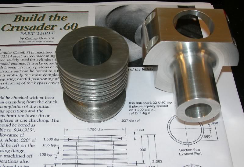
Well, I have taken the plunge and started the Crusader .60 that Home Shop Machinist Magazine published (Jul-Aug 2005) . It is a two stroke engine similar to a model airplane engine. It is a glow plug engine that runs on model airplane fuel. The author (George Genevro) used quite a few jigs in order to construct this engine using aluminum and steel bar stock.

My initial plan of attack on this project was to fore-go some of the jigs in favor of speeding up the build some; however, having a young son who is tending to want to spend more and more time in the shop with me has made the case to go ahead and build the project basically as published in the article. By using all of the jigs and fixtures and building the project this way, when he gets a bit older, he can build one himself without having to mess with making the jigs. With the build article, this should make the project for him easy to follow and can feasibly have a successful engine with getting bored of making tons of jigs.

Adding to this project is a good personal friend of mine. He has an interest in machining, and is building himself the same engine at the same time. Along with his engine, he also is building a full set of jigs for later use with his son. He doesn't yet have any machinery, but is budgeting to get a small lathe and mill when he can. He comes over one night each week, and makes parts for the engine. On that night, I will work on whatever machine is available or just stay out of the way to enable him the ability to machine his parts. The goal is to finish up the engines simultaneously, but with him spending only one night each week on the project, that is going to prolong the builds.


At this point in time, my engine is sitting with a crankcase that is 90% complete, and several of the jigs have been machined and prepared for later use. The other engine has the crankcase sitting at about 70% complete, and also has several of the jigs machined as well. All of the raw materials have been located or purchased and are set aside for the two builds. There are a few tooling items and fasteners needed in order complete the project(s). Other than that, just some time on the shop floor is the component standing in the way of two running engines.

Now, I know the question will be asked... Pictures. At this point in time, there hasn't been any photographs taken of the project(s). That will soon change. All that needs to happen is me getting myself in gear and taking some pictures of the current pieces, and then taking more along the way. Hopefully I can get those posted tomorrow.
 
W/E

Looking forwards to this one, I don't think we have had many builds on here that required holding jigs to be made so that you can progress onto the next stage.

Lovely idea as well, sharing your workshop. Two benefitting from one.

John
 
Here are a couple of pictures that I found on the internet of the Crusader. This will give an idea of what the finished engine is supposed to look like.
b1001.jpg
b1000.jpg


And, a few pictures of where things are at... And my apologies for such crappy pictures!

This was boring one of the crank cases on the lathe.
DCFC0017a.jpg


This is the crank case for the engine that I am building. I have deviated from the original design somewhat in the cosmetic department. I didn't really care for the square shape of the crank case, so I am going to add some curves and fins to it. The dimensions as far as the design goes are the same. This is a horrible image, but you can see it taking shape.
DCFC0043a.jpg


This is a picture of both projects. The set up on the left belongs to my buddy who is doing the build along with mine, and obviously mine is on the right. The example my bud is building will be to the origional design all the way. The jigs are also laying about, and I will do a better job of taking pictures of the build going forward. The stock laying in the various places is the remaining parts for the projects. We just haven't dug all of them out yet....
1002.gif

DCFC0048a.jpg


Now that I have some momentum, I am getting excited about this project!
 
Just what's needed W/E, a poke up the backside with a sharp stick.

Those bits are looking well.

John
 
Looking good so far. This a high rpm engine isn't it (> 5,000 rpm)?

Cheers,
Phil
 
Philjoe5 said:
This a high rpm engine isn't it (> 5,000 rpm)?

I am sure it will be. These small two strokers typically spin pretty fast. My guess will be it will top out in the 5k-6k RPM range. I haven't come accross any infromation on the actual engine performance. When I am done, if it will sputter and choke, then I think the whole thing will be a success!! ;)


Phil & John, thanks for the compliments!
 
Damn Sexy! ;D :bow:

Nice looking engine! GREAT silver solder job!
 
Great Job and an inspiration as I am embarking on my 1st IC engine; but mines a baby alongside your model, if my math is correct 10cc? assuming 0.6 = cu ins mine 3cc and a 3 port job, no valve in the crankshaft.

Please may I pick your brains, from what I have read my project would suffer from blowback due to the ?? excessive time the inlet port is open. I have made some changes to the porting/timing but don't know 2, (pretty vital),things.

1. Would it run as drawn?
2. Do my mods make it more or less likely to run? ;) :bow:

View attachment 3ccICD.pdf
 
Maryak,

I'm glad that my fiasco is an inspiration to some. ;D Before answering your questions, the engine that I am designing has all of the ports dimensioned for the various parts, so the actual timing curve on my model is an unknown to me. I would have to plot it out to compare mine with yours. And I may very well do that in the future if the engine doesn't perform well.


For answering your questions, I think that either design would run. I think that the original curve will run better through a wider range of RPMs, but the modified curve may run a bit better at higher RPMs. Again, this is a SWAG on my part.

The original timing curve looks like what mine will be for the most part. The port locations and geometry are pretty straight forward. Because of the lack of time between the port openings, my guess is this engine will run pretty smoothly. On the top end of the RPM range, I think that the engine's power curve will flatten off and limit the RPM range some. That isn't a bad thing, I am just guessing at how the engine will react to changes in timing.

The modifications to the original timing curve are going to allow the crankcase to be at a slightly higher pressure before the intake port opens, which will obviously aid in filling the cylinder. You should get a slightly higher compression from the denser fuel/air mixture, and my guess is this will help performance on the upper end of the power band. With the timing curve this way, my bet is the engine will not want to idle very well, but may have a higher RPM. Again, this isn't a bad thing, either.

To summarize, my guesses to possible engine performance are just that, guesses. By no means am I an expert on two-stroke engines, but I do understand how they operate. My answers (okay, wild arsed guesses) are based on my experience with four-stroke engines and how changes in timing affect them. The only way to know for sure is to build it and see what happens.

And I have to say this has me thinking now about the timing in the Crusader...
204.gif
 
W/E,

I found your last post really pleasing. You are showing what we all should do when building from plans.

Instead of just moronically machining shapes and dimensions, you are also attempting to understand how the engine works, and you aren't afraid to give your own opinions, whether good or bad.

Nice one

John
 
War Eagle

Thanks so much for your reply to my porting/timing query, I am much happier to start on the cylinder now. and your comments have prompted me to ask the kids/grandkids for a book for my birthdayfrom the UK "Model Engine Mechanics," self published by Gordon Cornell who I think was a design engineer for Frog which were around when I was a kid.
 
Bogstandard said:
W/E,

I found your last post really pleasing. You are showing what we all should do when building from plans.

Instead of just moronically machining shapes and dimensions, you are also attempting to understand how the engine works, and you aren't afraid to give your own opinions, whether good or bad.

Nice one

John

John, thanks!

Maryak said:
War Eagle

Thanks so much for your reply to my porting/timing query, I am much happier to start on the cylinder now. and your comments have prompted me to ask the kids/grandkids for a book for my birthdayfrom the UK "Model Engine Mechanics," self published by Gordon Cornell who I think was a design engineer for Frog which were around when I was a kid.

Maryak, you are very welcome. My best wishes for a successful build! Keep us up to date when you start your project and feel free to ask any questions.
 
Woo, Hoo!! I finally got some uninterrupted time on the machinery!! ;D Not very often that happens!!!

I made some progress on the Crusader. My buddy that is building one along with me is unable to join and won't for a while, so after visiting with him, I am off and running on mine. And I made a fair bit of progress today. It seemed like most of my time was building tooling for this project, so I opted to make some parts instead.

My apologies for the horrible images. These will be the last set that are of poor quality coming out of my shop. The camera I was using to take the pictures seemed to need a fine adjustment, so I obliged and grabbed my 16 oz. fine adjustment tool. 8) The camera didn't take the adjustment very well. ;D

I started with turning the cylinder. This picture is indicating the stock in the four jaw.
DCFC0018.jpg

For the newbies, a four jaw chuck does not self center the work in the jaws. You have to locate the center yourself. It is easily done with an indicator and a little time. The method I use is to chuck up the piece and eye ball it as close to center as I can. Once that is done, I will put the indicator on and see where things are at. Then, take one set of jaws at a time, and center your work piece. Once you have one set done, just repeat for the other set until centered, then double check all of the jaws to make sure nothing moved on you. With some practice, you can indicate a piece of bar stock in a couple of minutes to within .001".

This is drilling the bore in the cylinder. After this step, I bored the cylinder to .002" under size to allow for lapping.
DCFC0016.jpg


Cutting the fins on the cylinder. This step proved a bit tricky. I had some chatter on the cutter when I cut the first fin, and it took a little adjustment on the QCTP to get it to subside.
DCFC0020.jpg


And this is the cylinder atop the crankcase.
DCFC0030.jpg


The things that are left on the cylinder are drilling and tapping the holes for the base and head, and also milling the bypass slots and exhaust port.

The other things I did is I drilled and tapped the rear of the crankcase, and turned the rear portion of the crank shaft. That took a bit of time to get the geometry right and also to polish the rod journal. With the rear of the crank shaft done, the remainder will be straight forward, and hopefully will go smoothly.

 
W/E

Great to see you moving ahead. Were you using the dial indicator because you had to re-chuck or do you always do it that way? Just curious, back when Methusela played full back for Jerusalem, they would have kicked my butt good and hard if I used a dial indicator on black bar, (I notice yours is polished, if not machined where the indicator is). Chalk was the accepted tool for black metal and really fancy was a piece of metal in the tool post and white paper on the saddle!

Neat design with the cooling fins integral with the cylinder, I've got to make this Aluminium pot which doubles as the fins and cylinder head.

Keep going mate and thanks again for your advise and support.
Bob ;D ;D ;D
 
Maryak, the dial indicator was indicating on a machined portion of the stock. You are correct that typical stock is out of round, and sometimes by a great deal!

Thanks!
 
Well, I thought that I would give you guys some better quality images. The other camera I was using must have had a lens made from Saran Wrap. The optics were horrible!!

This is the cylinder and crankcase awaiting more operations for completion. The crankcase lacks four tapped holes for the cylinder flange, and then the fins on the bottom (a bling item).
DSCN3307a.jpg


This is where the crankshaft is currently. The journal has been turned to dimension and polished, and it has bee centered in the four jaw to turn down the main journal. There is a hole in the main journal for bushing lubrication and that has now been drilled.
DSCN3303a.jpg


Now, I am off to my favorite place, the dawg house! ;D Gonna make some more chips this evening!!
 
W/E,

Great shots ;)

Interesting way of machining the crankshaft.

I've done it your way, i.e. journal 1st, between centers when making a solid job at 12" = 1ft, and a single throw with mains either side, (that way you don't turn off the centers of the main shaft). Then onto the other centers for the mains.

My plan is to turn a 1-1/16" dia and then turn and lap the main shaft, 5/16", all at one setting.

Next make a slotted bush with a hole offset to 1/2 the stroke and mount this in the three jaw, where I hope it will grip the main shaft and allow me to turn and lap the journal. ::)

Watdeyathink ???
 
Bob, I don't see why it wouldn't work.

As far as the way I am machining this part, I am basically following the setups that the article stepped out. I am not convinced that this is the easiest way, but I couldn't come up with an easier plan myself, so decided not to reinvent the wheel.

I made it a litle ways before I decided to call it a night out there. After being sick for a week, I am am still weak and just finding myself not concentrating on the work as close as I realy should be. So, the logical thing to do is stop. And that's what I did. It will be there another day.
 
I reckon you are some 14-15 hours behind us timewise, so must be close to beddybyes ;D and I'm sorry you had the flu or some nasty virus.

I like your plan to stay away from machines if the concentration's off. That way not only will the job be there tomorrow, so will you ::)

Thanks for your comment on my proposed method.

Best Regards
Bob
 
Maryak,

I have been down for a week, but I use the term down loosley here. I have had some sort of respitory somethin' that is making me cough like a dying emphesema patient, and I just don't have any steam. Have had very little fever, and that was low grade. Top it off with a little sinus congestion, and a loss of appetite and you now know what I have been feeling like for seven days. I'll make it, and I think I am turning the corner now with it.

Getting away from the machinery when not 100% on the game is vital for survival - operator survival and use the part later! It's okay, I'm not punching a clock out there and there is no deadline that I don't have control over, so I could think of no reason to continue.

BTW I am glad you liked the shots. Camera quality does make a huge difference in what your pictures look like. This thread is a great example of that.
 
Back
Top