I missed out a few photos of the next stages but this is what I have.
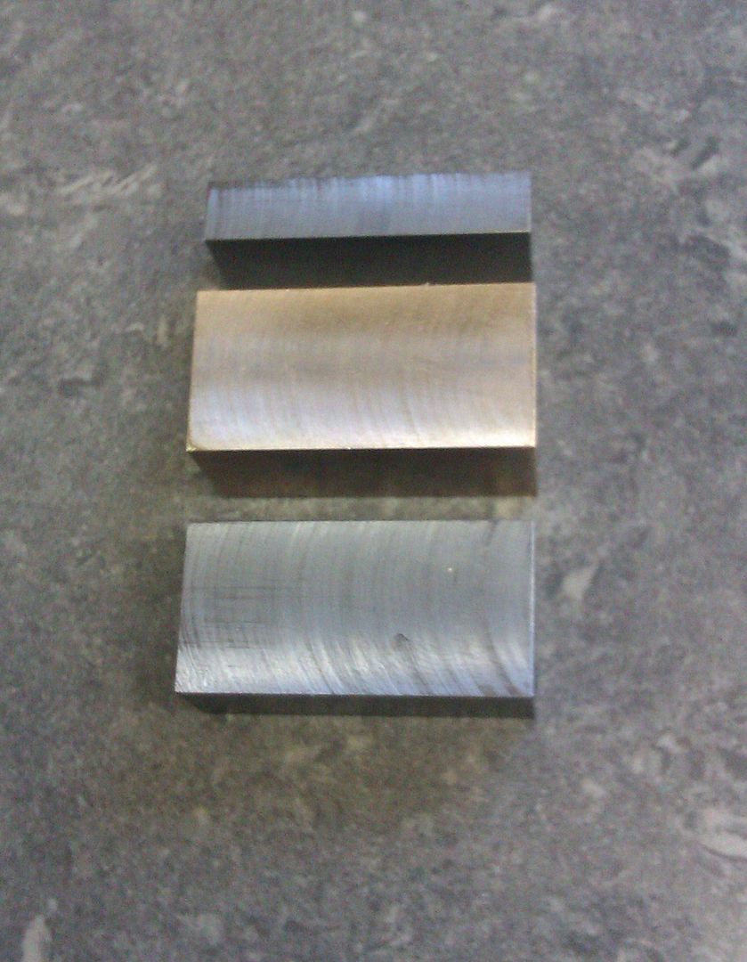
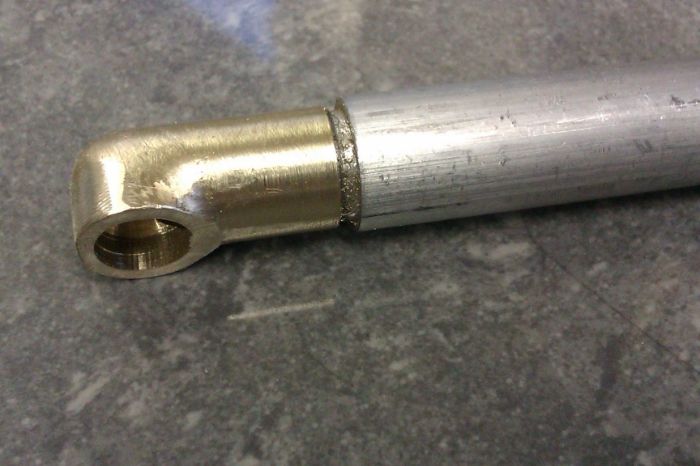
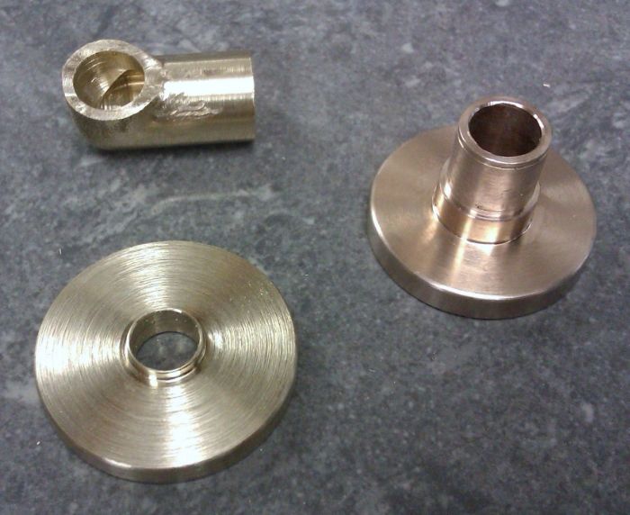
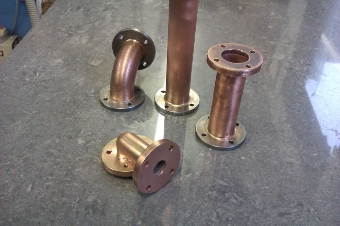
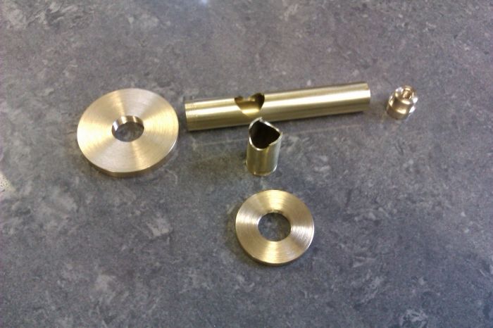
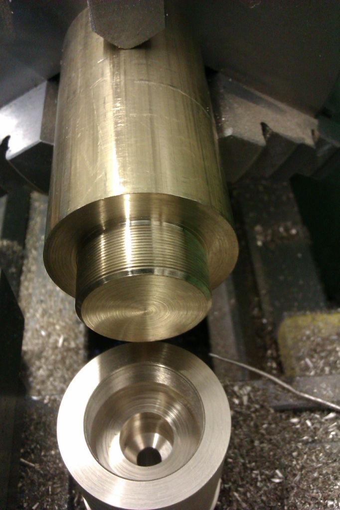
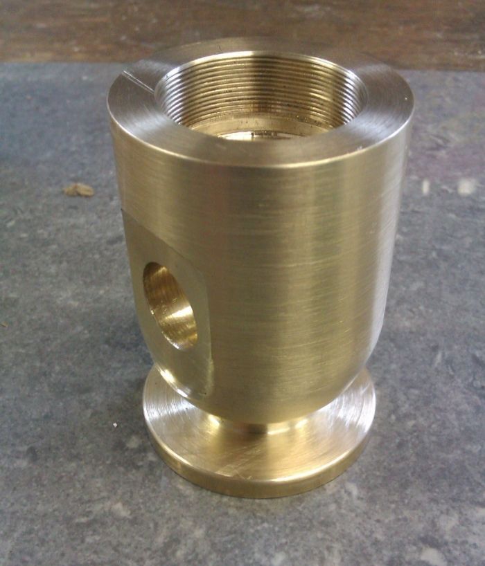
The parts for the regulator valve prior to soldering.
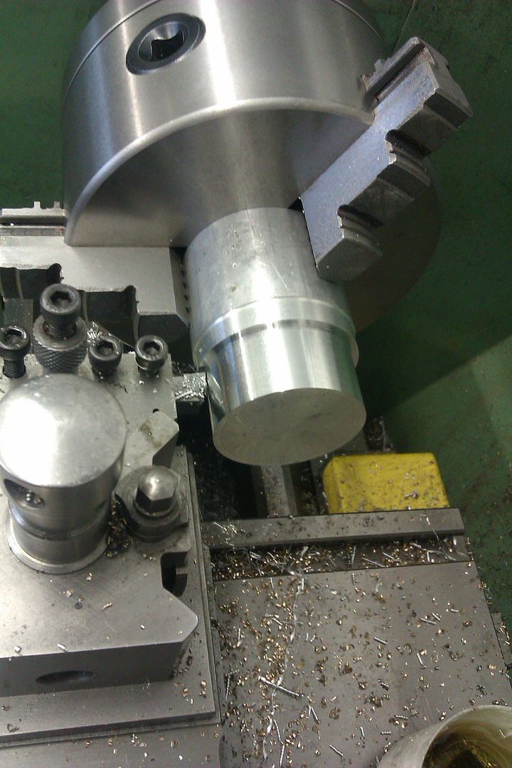
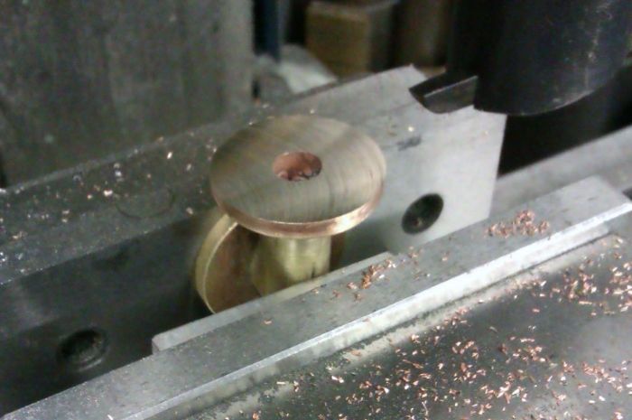
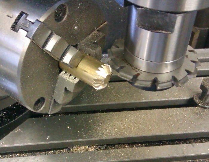
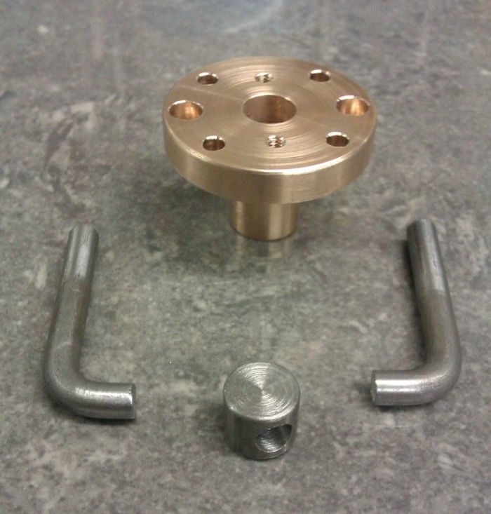
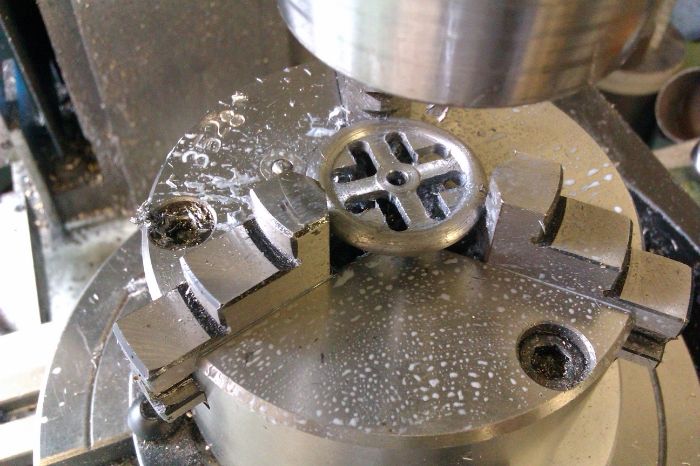
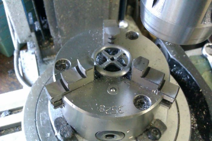
The profile of the valve handwheel was machined on the lathe before transfering to the R/t to first cut the spokes
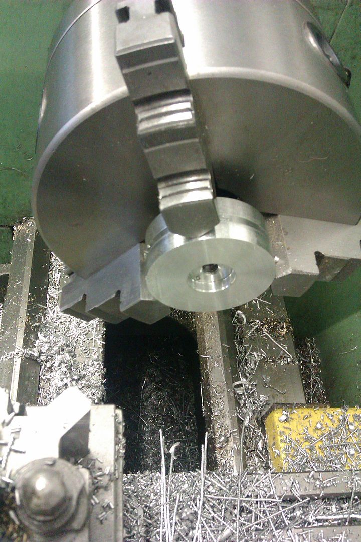
And then remove the waste
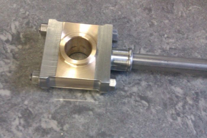
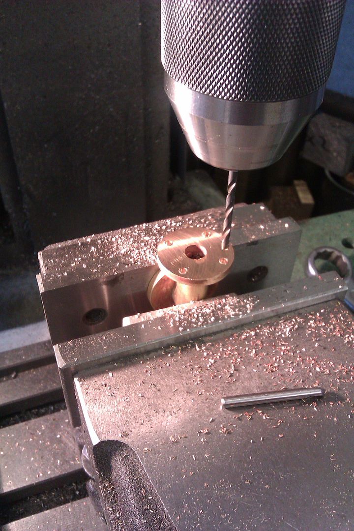
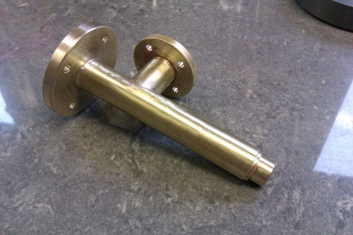
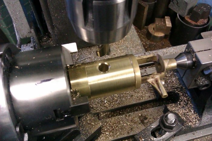
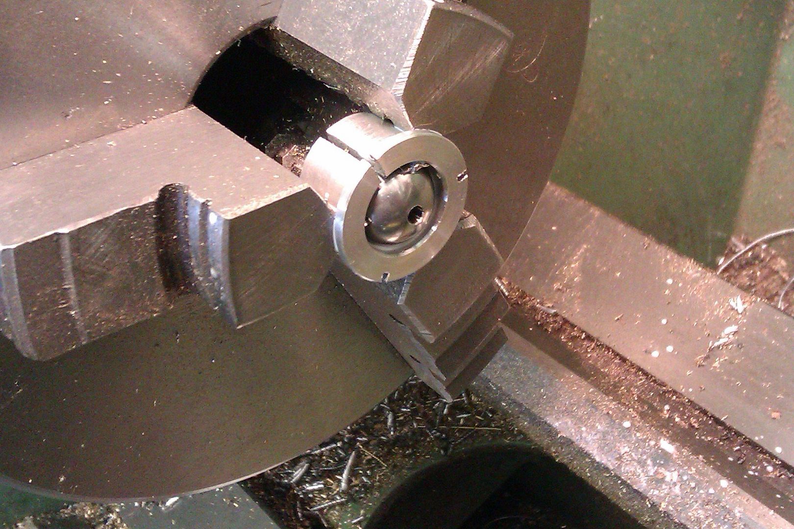
While the R/T was set up I used it to cut the two large radii on the stuffing gland
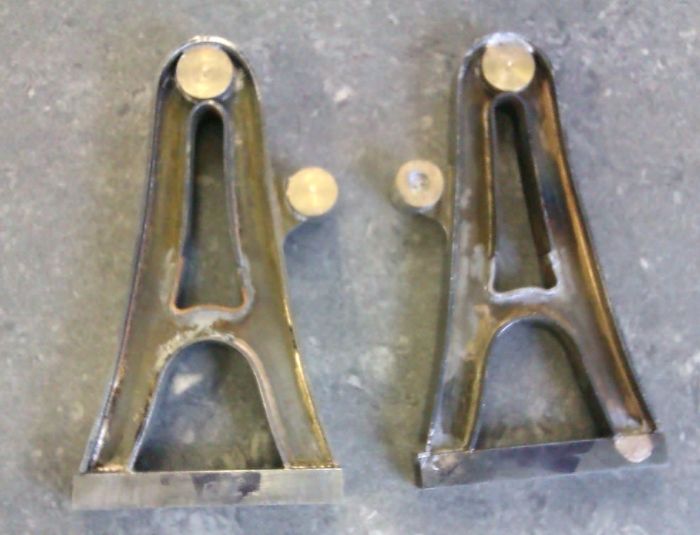
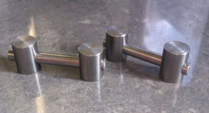
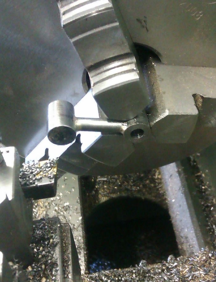
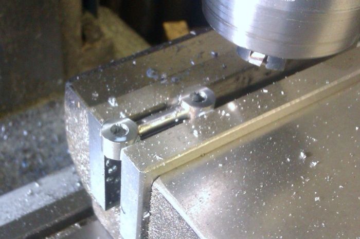
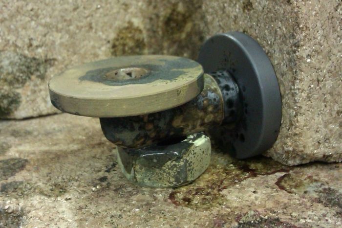
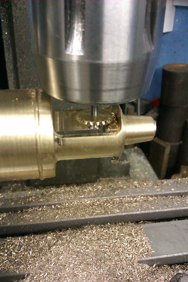
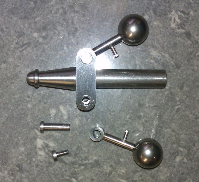
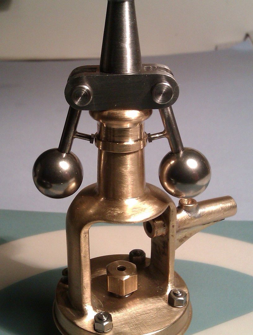
I decided to use commercial balls for the governor, these are 303 stainless and reasonably easy to drill in their supplied state. A split collet was used to hold them for drilling
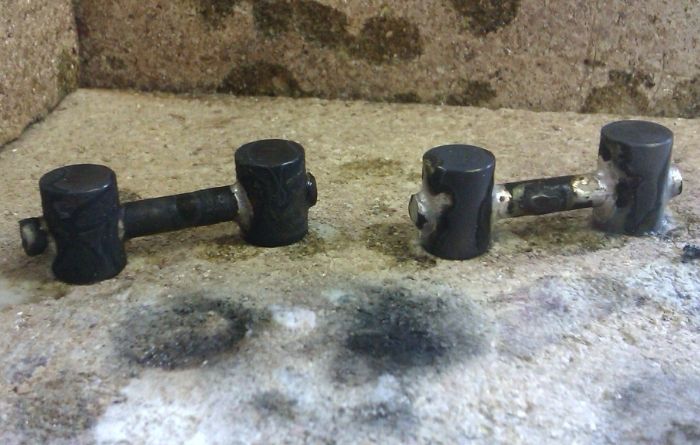
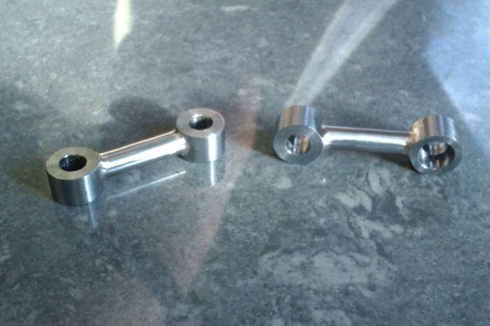
These were loctited to the arms, I also made the small tee shaped legs that stop the balls dropping too far
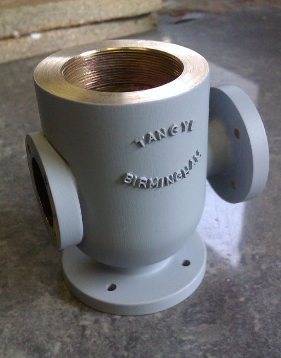
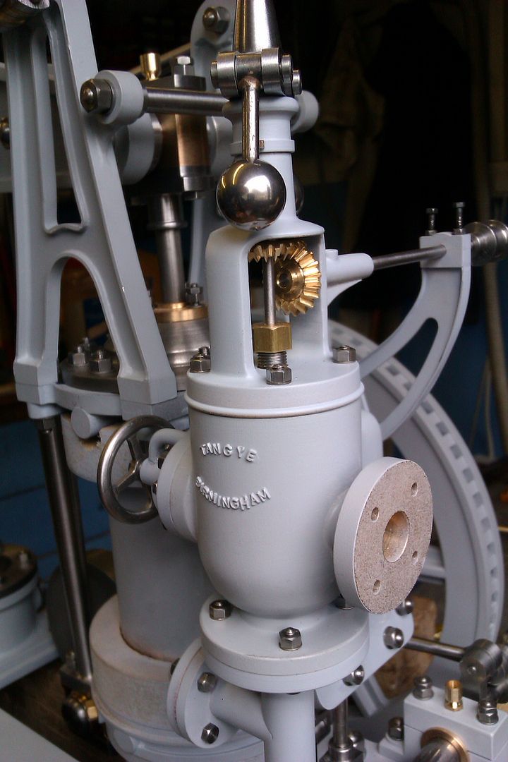
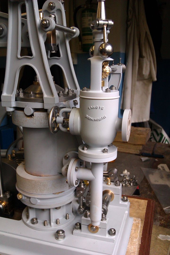
As this engine is only likely to run on air I added a finishing touch with some "Slaters" letters, these are 2mm high
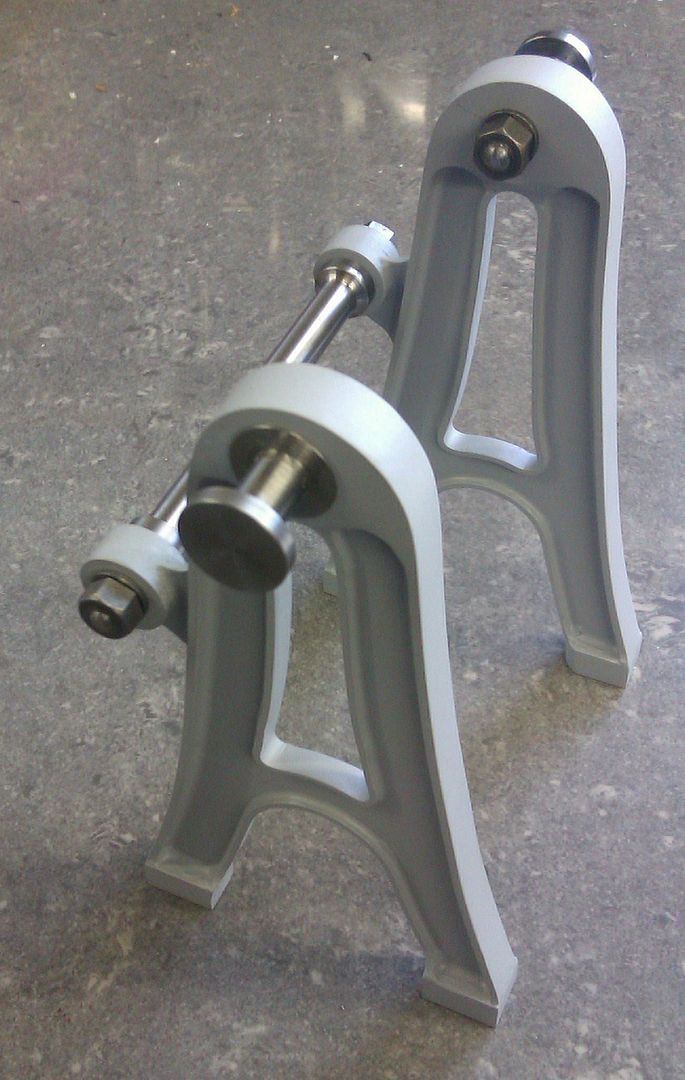
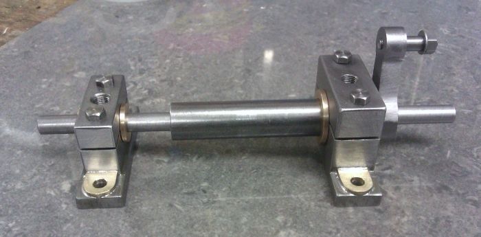
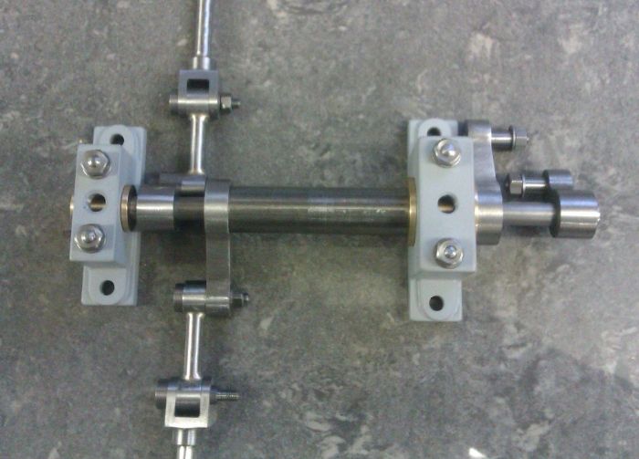
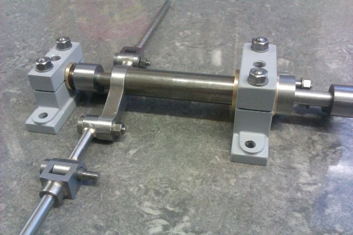
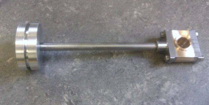
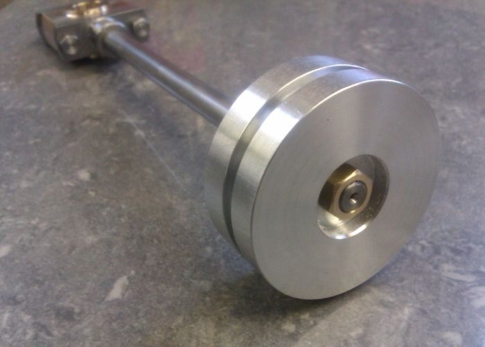
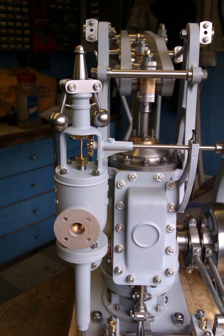
And here are a few shots of all the bits fitted together, the eagle eyed of you (Jo) will also spot the bracket to support the other end of teh governor drive shaft.
J


")