Building a bigger Easton & Anderson Grasshopper

Home Model Engine Machinist Forum

Help Support Home Model Engine Machinist Forum:

This site may earn a commission from merchant affiliate links, including eBay, Amazon, and others.
Still following, lost in admiration for the way in which you make those complicated parts.

Jim
 
Hi Jason

Great update!

Thanks for taking time to share your progress with us.

Dave
 
Next up is the beam or more presisely the beams as there are a pair mounted back to back with all the rods etc fitted between. I started out with two pieces of aluminium flat bar 3/8"x 2" just over the required 11" long and squared off one end.

IMAG1089.jpg


They were then blued and stood vertically on the squared end and clipped to an angle plate to mark out the hole positions. Mostly now I don't do this prefering to just locate an edge/end and use the DRO to position the holes but I wanted to mark in the outer diameters of the bosses.

IMAG1091.jpg


Here the bosses have been scribed in and the outline drawn to touch the various radii

IMAG1092.jpg


The beams were then clocked true on the mill and the holes all drilled using the DRO, the largest hole was finished with the boring head. I tend to use stub length drills in the common sizes as it saves having to crank the mill head up and down so much, they are also more rigid so tend not to wander.

IMAG1093.jpg


The vertical bandsaw was used to trim off the waste from around the outside and then the edges were flycut back to the layout lines.

IMAG1094.jpg


I set a pair of buttons in the back tee slot of the mill with a parallel against them, this then gave me a reference face to set the beams against rather than having to clock them in for each of the eight edges. I then used a 3 flute FC-3 type cutter to remove half the thickness of the plate. The edges were offset from my ref parallel and I stopped just clear of the scribed boss outlines.

IMAG1096.jpg


With as much metal removed as possible I setup the rotary table and using various mounting mandrels proceded to round off the two ends and around each boss

IMAG1097.jpg


This shows all the milling completed

IMAG1100.jpg


Rather than use a ball nose or radius corner cutter to do all this milling I opted for a square edged one as they are far quicker at removing metal and there were also several cutter diameters needed but only one fillet radius. I put all the fillets in using Milliput putty as there is no need for any structural strength here, its just cosmetic.

IMAG1102.jpg


A good heavy coat of primer was stippled into the recesses to give a little "cast" texture followed by a blast from the spray can.

IMAG1107.jpg


The remaining work was just carful turning to produce all the various spindles and spacers, this used about 18" of mostly 5/8" dia steel rod and luckily it all went together without getting jammed.

IMAG1118.jpg


J
 
This is going to be quite a special model. Following as ever :D

Where did you go for the digital readout for your mill? My new SX3 is being delivered next week...

Rob. :)
 
Allendale / Machine DRO call them what you will. They are the GS500 slim scales & covers and universal console.

I believe you can get similar from singapore via e-bay for less.

J
 
Hi Jason,
Gus planning to buy a DRO too. Missed the 6 sets Heidehahns I bought for the Ingersoll-Rand plant,in Singapore for the Leblonde Precision lathes,Bridgeports and the heavy plate rollers etc.
But my three open sided Balcony Machineshop makes me think twice because a bad rain storm will do some damages. Also planning to put in a bigger "Sakai" Vertical Mill to take heavier cuts. The current mini mill cannot operate too long w/o motor overheating.
If budget permits,will close up the three open sides and have w/shop airconned.Keep you posted.


By now.About to work on my second attempt to make the QCTP with cam lock.
 
Gus, you have mentioned your balcony several times. Do you do anything to protect your machines?

Pat
 
Well people, sit back and observe another POM coming along! (has to become a POM!!)

Jason, great work there!!

Cheers, Karsten
 
With the beam and end support frame done I decided to tackle the cylinder next as this will eventually allow me to support the other end of the beam. I started with the base flange, this was sawn into a octagon from some 5/8"x4" flat brass bar and held in the 4-jaw to trepan out the centre. I went almost half way from each side then took it out of the lathe and gave the middle a whack with a hammer and the central disc dropped out.

IMAG1120.jpg


The bore was cleaned up and then used to hold the flange by while the outer edge was machined round.

IMAG1122.jpg


I then preceeded to do the same for the top flange but from 1/4" thick material, it was just as I finished trepanning out the middle that I remembered I should not have cut the corners off :wall: so substituted a piece of 1/4" steel as I did not have another piece of brass large enough

IMAG1126.jpg


The main tube of the cylinder started life as a length of 2 1/2" hollow cast bronze

IMAG1124.jpg


The outside was turned down to 2.375" and spigots formed on the ends for the flanges to fit onto. At this stage the bore was left undersize for finishing after fabrication, the overall length was also 1/16" bigger than needed so the flanges could be skimmed back true to the finished bore.

IMAG1125.jpg


A lump of bronze was sawn to give me a finished block of 3.25 x 1.5 x 1.75 and this was flycut to get all faces square.

IMAG1127.jpg


Finally a bit of 1/8" brass sheet was cut to make the flange for the valve chest cover to bolt to and here are the roughed out parts.

IMAG1128.jpg


I used a boring head to cut the curved face of the valve chest

IMAG1129.jpg


The chest was then cut off at 20degrees, the chamber roughly hollowed out and the angled face flycut. I also cut a matching hole in the bolting flange and added a few 10BA CSK screws to hold the two together when soldered.

IMAG1132.jpg


IMAG1148.jpg


Starting to look a bit more like the original now

IMAG1134.jpg


As the cylinder was comming together it became obvious that I would have difficulty holding it to take any heavy cuts off once assembled as I could not get it into my fixed steady so I decided to do a bit more work on it before soldering. Also the valve chest needed quite a bit of heating to get the solder to flow and by removing any unwanted metal the bulk would be reduced making for slightly easier heating. Here is the cylinder barrel getting opened out.

IMAG1147.jpg


I also shaped the top flange, now you can see why I needed the corners, they will support the "A" frames which help retain the beam.

IMAG1149.jpg


Once all the parts had been machined I silver soldered them together, It went OK but not what I would call perfect as it was hard to get enough heat into the big lumps of bronze. Once cleaned up I spent a long time clocking the cylinder true in the 4-jaw both for concentricity and alignment to the lathe axis, changed the QCTP to the 4-way that came with the lathe so I could mount a 7/8" boring bar and just skimmed the bore with several very light passes followed by similar light cuts to the top flange.

IMAG1152.jpg


On a safety note, don't try this unless you know what you are doing there is a lot of unbalanced metal hanging a long way out the chuck. If in doubt then don't.

This post is getting a bit long now, next time I will true up the other faces and start adding the 64 assorted holes!!

J
 
With the top of the cylinder turned true to the bore it was a simple job to bolt that surface to the mill table and machine the bottom and to get the final overall length.

IMAG1153.jpg


After that the flange around the valve chest was skimmed

IMAG1151.jpg


I then clamped the cylinder between two angle plates and finish machined the valve chest and drilled the ports. Anthony mount quite often uses drilled ports rather than milled slots which are a lot easier to deal with and seem to work just as well on engines that are unlikely to do any real work.

IMAG1159.jpg


The exhaust passageway was then drilled through and the hole threaded and spot faced to 5/8". A similar hole was added on the other side for the steam inlet

IMAG1161.jpg


With the cylinder stood the right way up the centre was located and the two steam passages drilled down to the ports and milled through into the cylinder. These are a little closer to the outside edge than I would have ideally liked but not being 100% happy that the solder had flowed between tube and valve block I decided not to drill diagonally as this would pass through the joint line.

IMAG1162.jpg


The other end was tackled next, first by clocking the bore

IMAG1164.jpg


Then with clenched buttocks I proceeded to drill the two 4mm holes through the bronze, as you can see by the amount of drill left in the chuck jaws the holes are quite deep!!

IMAG1165.jpg


While at this setting I milled the passages as per the top, added stud holes and the two gland holes for the valve rods with their associated stud holes.

IMAG1166.jpg


The 5BA valve chest cover mounting holes were than drilled and tapped

IMAG1169.jpg


There are several odd bosses and flanges on the casting these were knocked up and fixed with JB Weld

IMAG1170.jpg


And after a bit of a clean up and drilling the pipe flanges I gave the cylinder a coat of etch and this is how it looks at the moment, The last photo will give an idea of the size. I have also bonded on two rings of moisture resistant MDF to help support the planking that will be used to lag the cylinder

IMAG1201_zps750393ab.jpg


IMAG1203_zpsd96534c2.jpg


IMAG1202_zps08b534fb.jpg


IMAG1204_zps4ea81c19.jpg


J
 
As the flange on the valve chest is angled the cover is not the usual flat plate so has to be angled to match the chest. There is also quite a radius to the top so I started out with a strip of brass and held this against a 1/2" rod in the mill vice. The Rod was set level on a pair of 123 blocks so the brass could be checked for true with a square against the top of the vice jaw.

IMAG1171.jpg


It was then just a case of holding a block of wood agaist the brass and gently bending it over, the block of wood helps keep the bend where you want it and the rest of the strip stays straight.

IMAG1172.jpg


I was a bit short of 1/8" brass sheet so silver soldered the flange from 4 bits of 5/8x1/8 flat which I have an excess of, two oversize triangles for the sides also came out of this flat.

IMAG1173.jpg


The bent strip and sides were then silver soldered together, cleaned up and the 1/8" edges rounded over

IMAG1175.jpg


This assemble was then Silver soldered to teh flange, I used an old toolmakers clamp to make sure things stayed together

IMAG1176.jpg


And after a quick scrub under the tap we can see a nice small fillet of solder

IMAG1178.jpg


The mounting holes were then drilled and a small bezel for the makers plate soft soldered on.

IMAG1180.jpg


J
 
You may remember that when I was cutting the brass strips for the chequer plate that I said the method may work for cutting planking to go around cylinders, well now is the time to try it out.

I had some old mahogany that I ripped out of a house that was built about 1908-1909, it was the tops of some shelves in the alcoves either side of a fireplace that I replaced with this. It was machined down to 3/8" thick which was the width of plank that I wanted and then cut to the correct length to fit between the cylinder end covers.

IMAG1182.jpg


I then held it in the mill vice and used a slitting saw to slice of 1/16" strips which will need little if any further work

IMAG1184.jpg


And here they are tried up against the cylinder, there are a couple of brass bands to add and some small screws that will go into the MDF rings below.

IMAG1185.jpg


IMAG1186.jpg


Bit of a short one this week but I will make up for that in the next installment.

J
 
Next on the list was the conrod, this is made from a 9" length of 5/8 x 1 1/4 flat steel

IMAG1181.jpg


When this was cut I thought that while I was setting up the machines for the conrod that I may as well do all the other similar rods in one go so also cut some steel for the two eccentric rods, pump rod and two tie rods

IMAG1200.jpg


After squaring off the ends to length each bar was held on end and the two bolt clearance holes drilled together with a small centre hole formed with a BS 0 centre drill

IMAG1191-1.jpg


Each bar in turn was then held in the 4-jaw with tailstock support to reduce the majority to a cylinder followed by adding a slight taper to each end for about 1/3 of the length

IMAG1192-1.jpg


The tapers were then blended by hand to give the traditional fish bellied shape

IMAG1193-1.jpg


I then set the rods to one side and cut some bronze and steel for the bearings and end caps

IMAG1210.jpg


The bronze was then machined to thickness with a flycutter

IMAG1214.jpg


Before being tinned with soft solder prior to being sweated together

IMAG1215.jpg


The bearings were then flycut down to the finished sizes

IMAG1216.jpg


Then set up a stop on the mill vice so the bearings and plates can be drilled for the bolts

IMAG1217.jpg


And here they all are ready for assembly

IMAG1218.jpg


Well actually the bearings were bored first and the widths reduced to leave a raised section around the bore

IMAG1219.jpg


With then now assembled the narrow edges could be turned and recessed

URL]


IMAG1221.jpg


Must be doing something right as the two tie rods seem to have ended up the same length

IMAG1222.jpg


And them all completed

IMAG1265_zpsf75ce7af.jpg


Well I said it wass going to be a long one, so will the flywheel thats comming next.

J
 
You make it look sooo easy. Very deceptive. They look great.

Jim
 
Gus, you have mentioned your balcony several times. Do you do anything to protect your machines?

Pat

Hi Pat,

There is an oversized awning roof to keep away the hot sun and rain.
It is 99 % weather proof but on a very bad day some fine water drops do get in but the floor and machine tools doesn't get wet. Rust is not a big problem its the damp that upsets me. However some WD 40 helps.

Digital Calipers are stored in the house. May consider a very simple DRO and make it detachable easily. I missed the "HeiddenHahns" DROs and the Leblonde Regal Lathes.
 
This is a great build log, Thank you for doing it. I have seen several techniques I may be able to use.

I like your fabrication of large parts with silver solder. It appears they are soldered at one heat, is this correct? Do you apply the solder as the joint gets hot from a long stick, or do you cut pieces of solder and lay them around the part so they melt into position?

How do you deal with mixed horizontal and vertical joints, like in that base 'can' with the top and bottom and all the gusset pieces?
 
Lovely Job Jason :)
Pete
 
Ron I generally try to do it in one heat but if it needs two then I try to arrange something to hold the previously soldered parts together.(see pully and valve chest cover) The second time the solder is heated it will not melt at the same temp as the new joint but there is still a risk of things moving even with step soldering where different temp solders are used.

I feed the stick in when I see the flux turn to a liquid.

If you look at the cylinder base you should see that all the webs fit into small radial groves in the flanges so they can't move during soldering. And as I don't use the loose bits of solder there is no risk of them all dropping to the bottom, just feed in the stick where its needed
 
When I first started to think about scaling this engine up I had intended to machine the flywheel from a slice off a 10" dia CI bar but having got the additional photos I had to have a rethink due to the barring holes in the outer rim, these were used to manually turn the engine over to a point where it would self start.

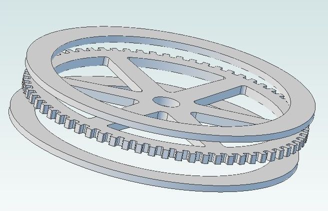
I eventually settled on the idea of a built up flywheel consisting of a "spoked cog" with a ring either side to give the the rim some thickness and add the webs to form the "+" section spokes plus a hub. I did think about milling out the spokes and the 66 barring holes but in the end opted for having them waterjet cut from 8mm mild steel with the two rings from 6mm material. A drawing was produced in Alibre and e-mailed to the cutters for a quote.

flywheelexp_zpsca85c659.jpg


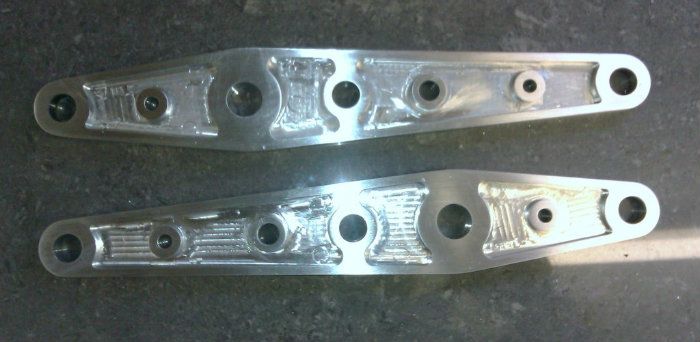
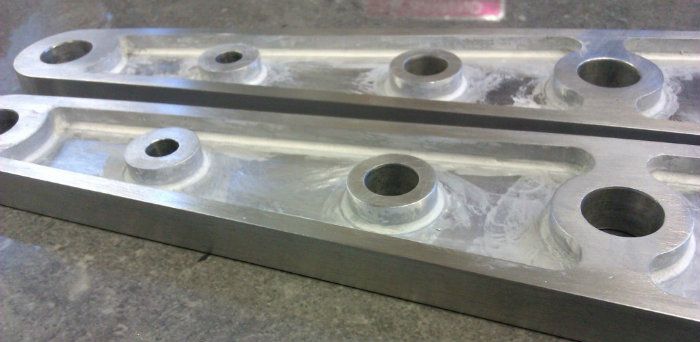
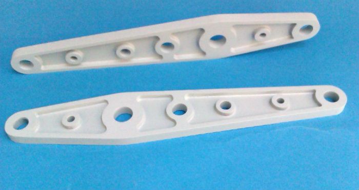
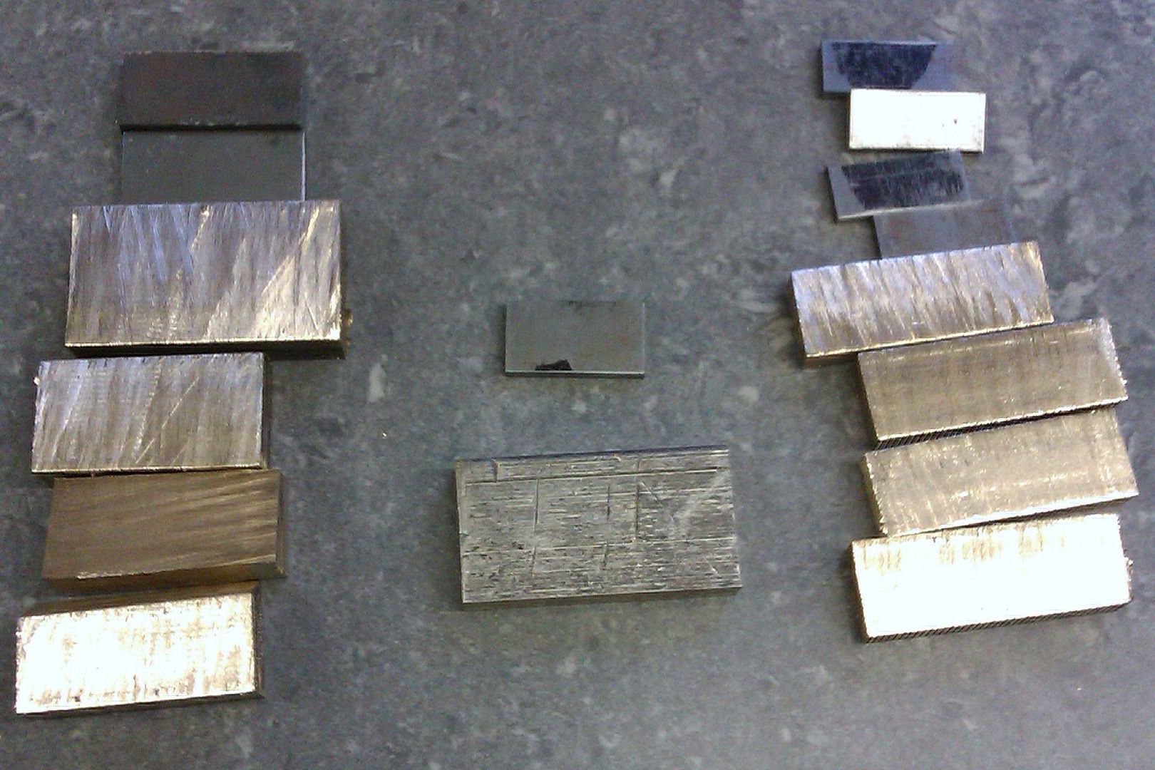
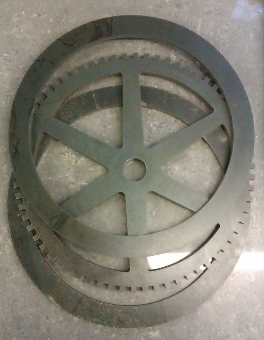
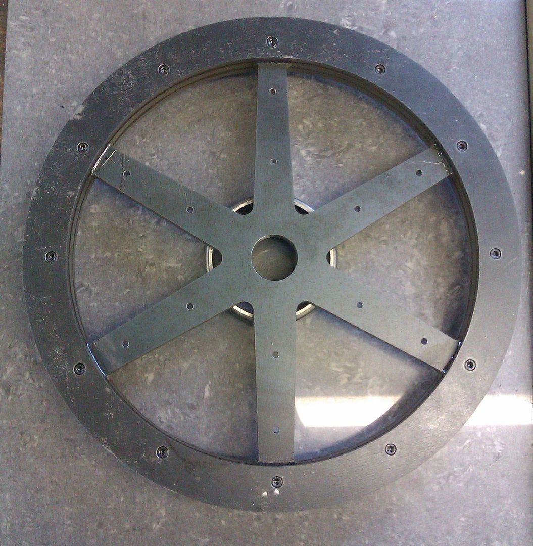
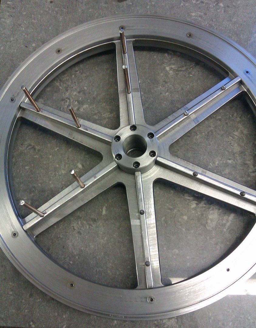
When this came back the price was OK so the order was placed and a few days later I got a mail to say come and collect, this is what I came back with, you can see that all the internal and external corners of the barring holes are radiused as per my drawing.

IMAG1240.jpg


IMAG1243.jpg


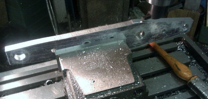
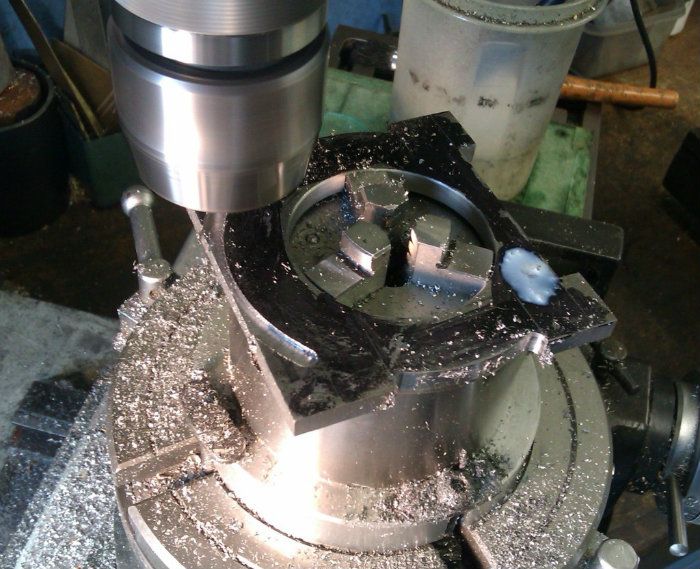
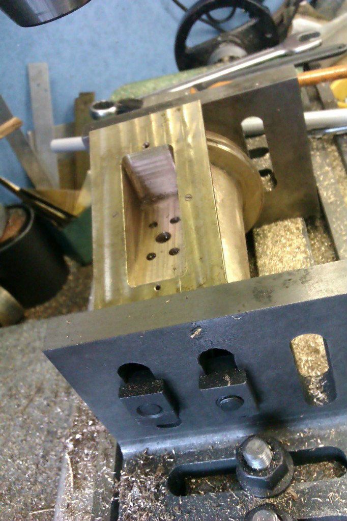
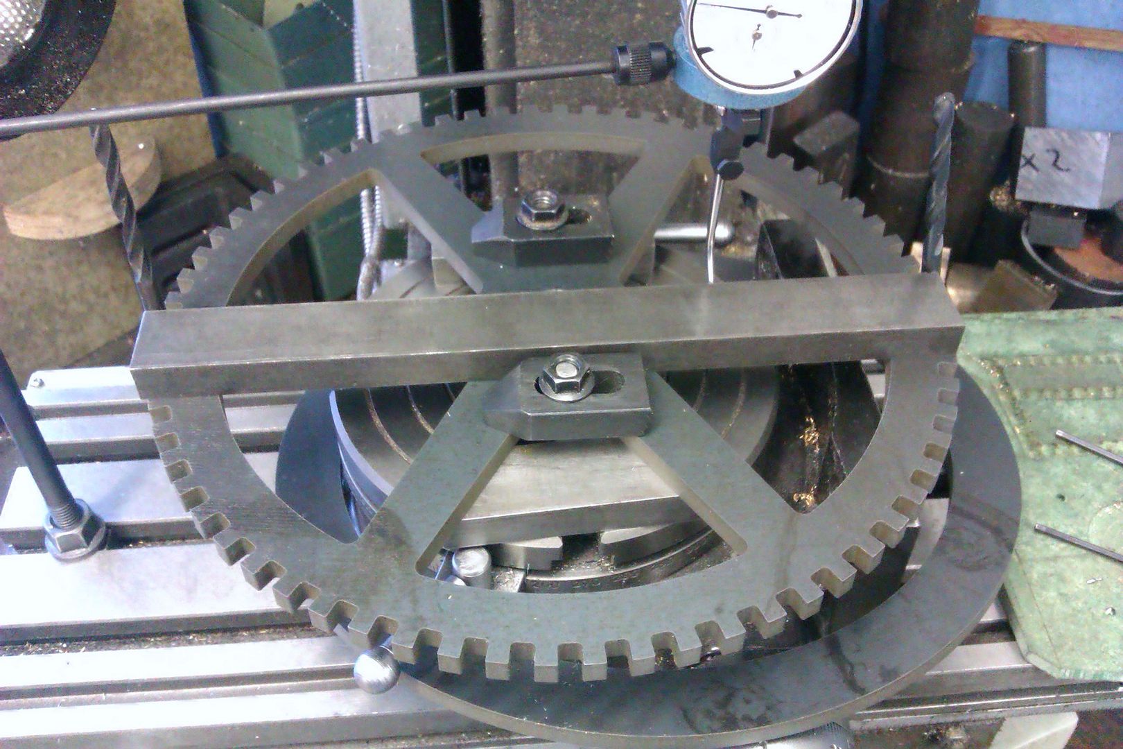
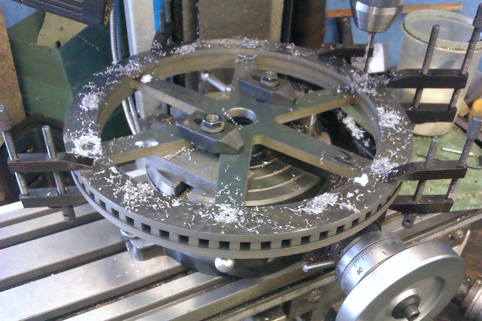
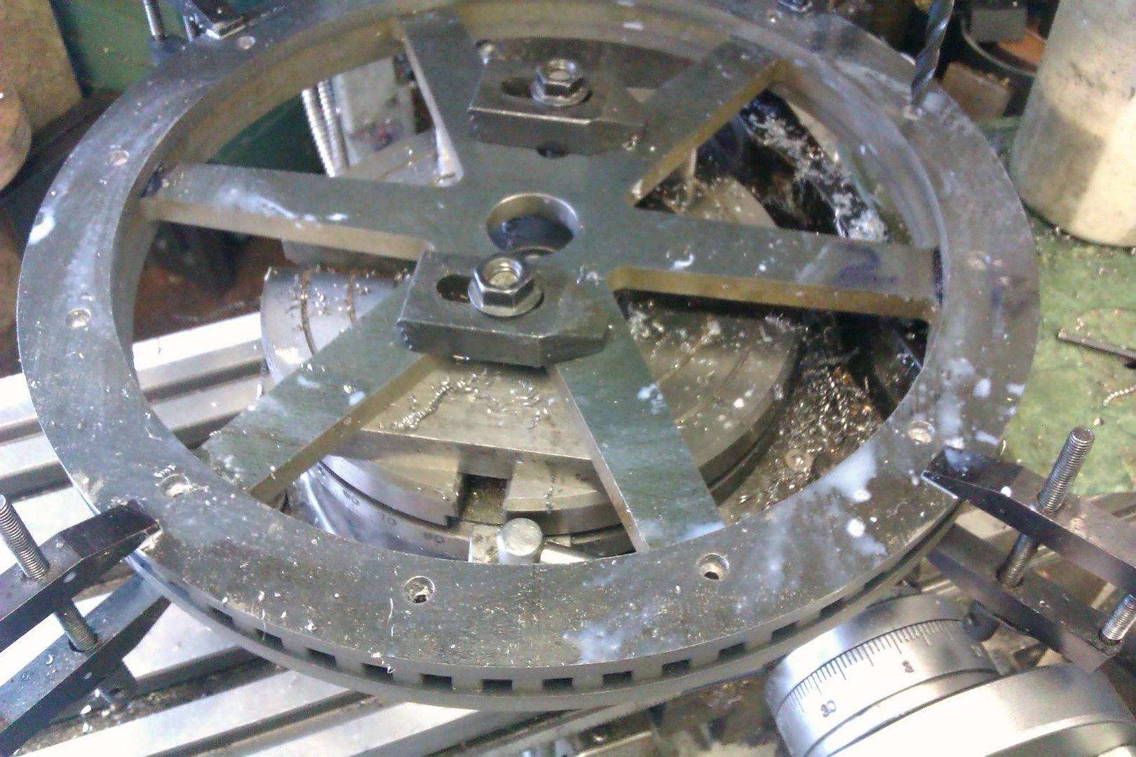
The first job was to join the cog and rings together so I set them up on teh rotary table with teh centre finder and while that was in the mill used it to set the wheel true to the Y axis, notice how accurate the 6mm notches are as they hold two 6mm drills in place to locate a straight bar against.

IMAG1244.jpg


I then clamped the three parts together and drilled through them all M3 tapping size

IMAG1245.jpg


Followed by clearance size in the top two layers and a counter bore for the M3 socket screw heads.

IMAG1246.jpg


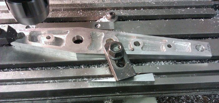
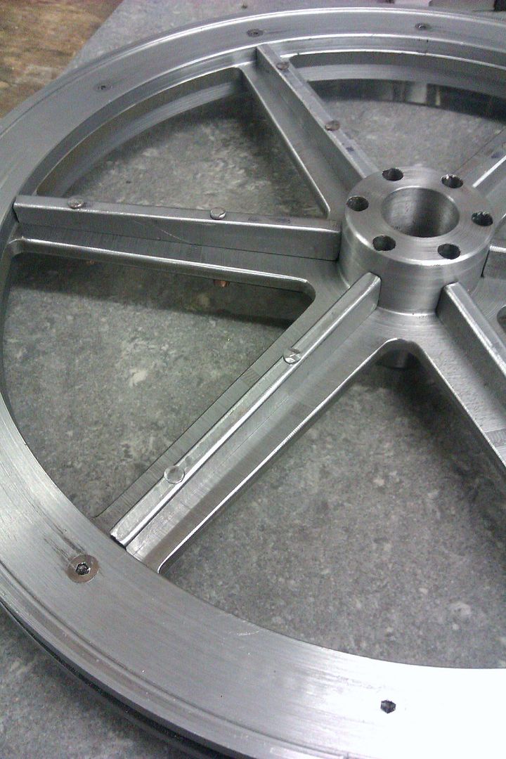
Once out of the mill the lower ring was tapped and a trial fit done, you can also see that I have drilled two dowel holes in each spoke, more on them later.

IMAG1253.jpg


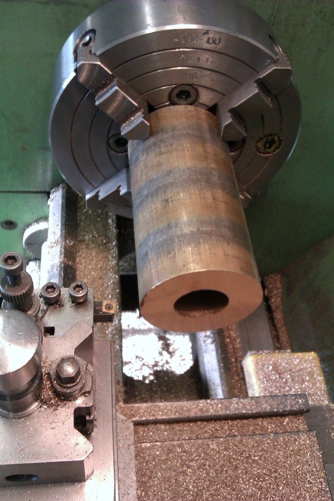
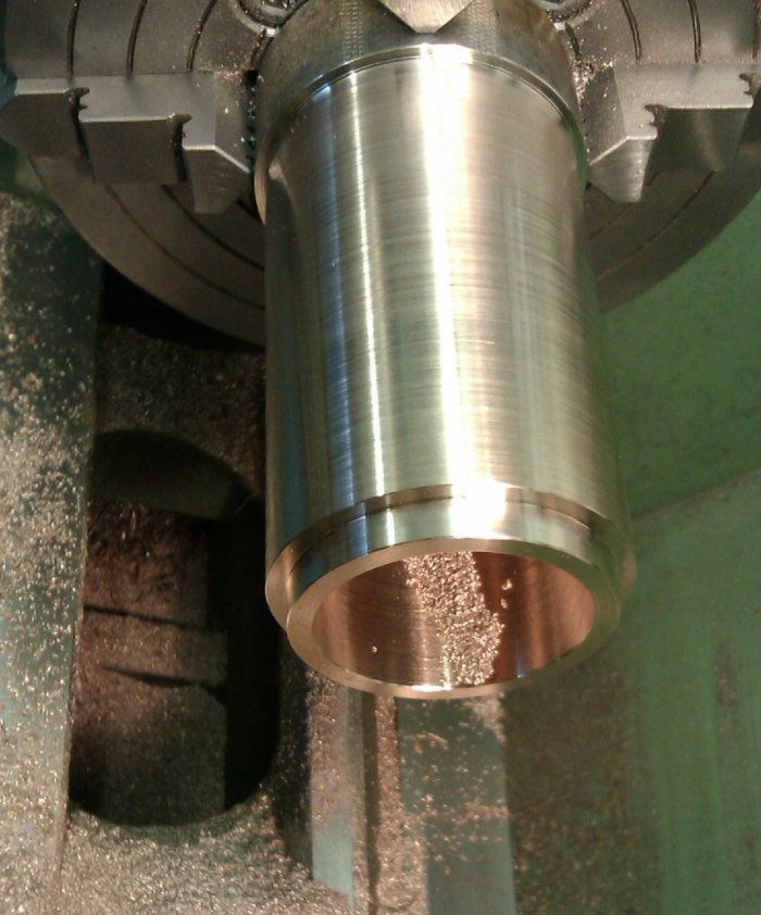
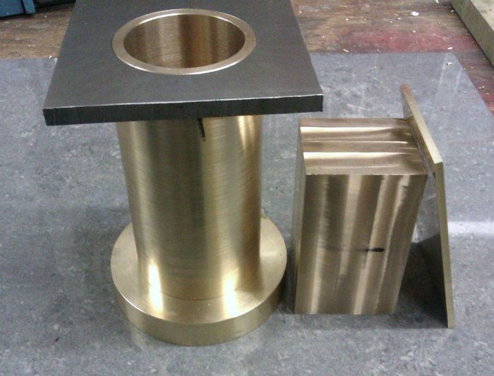
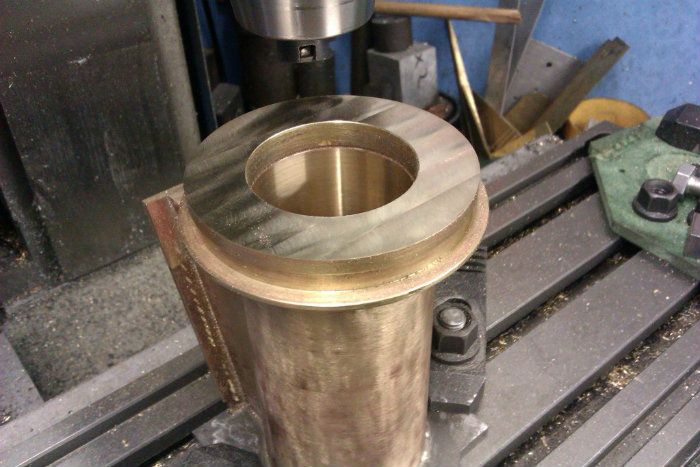
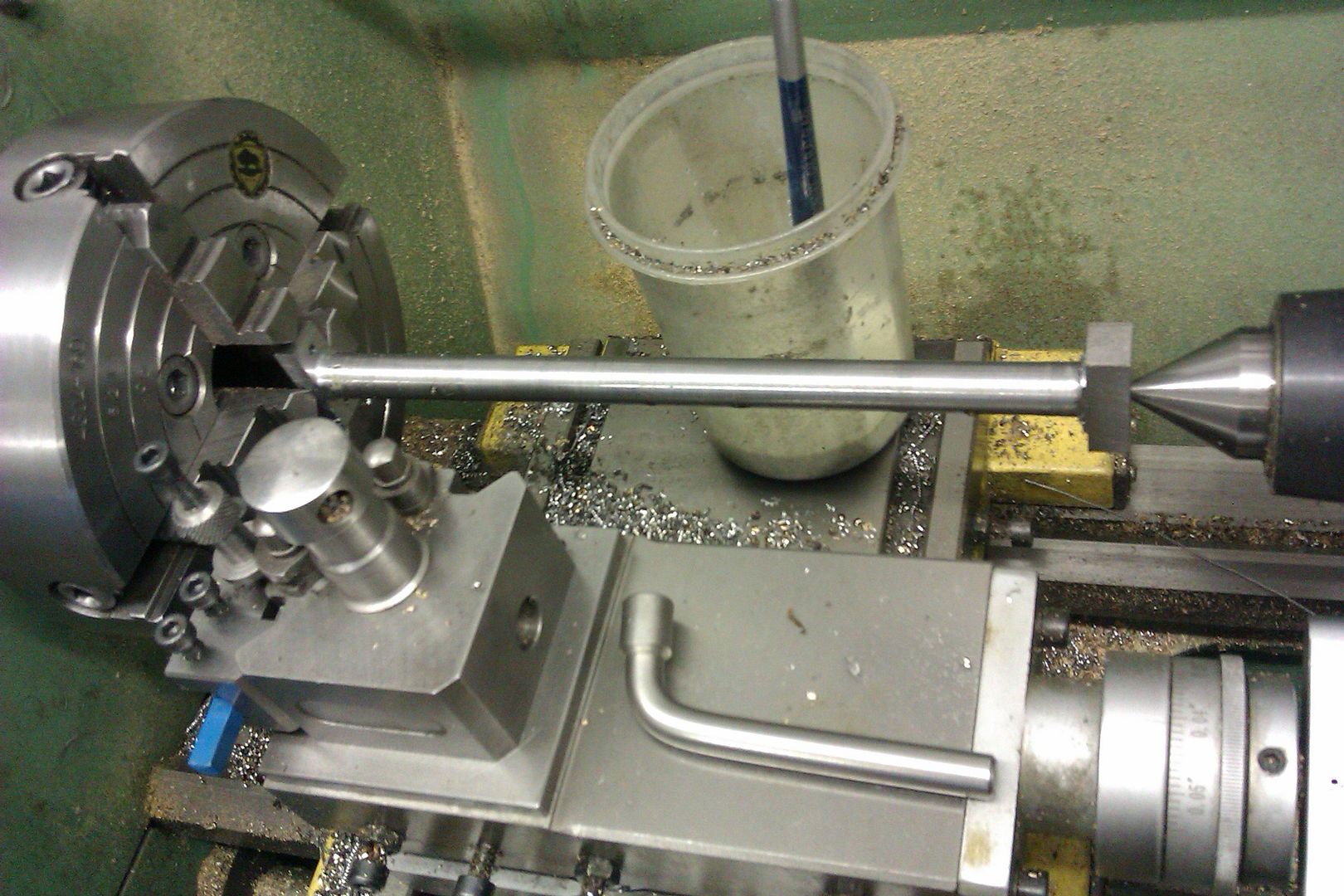
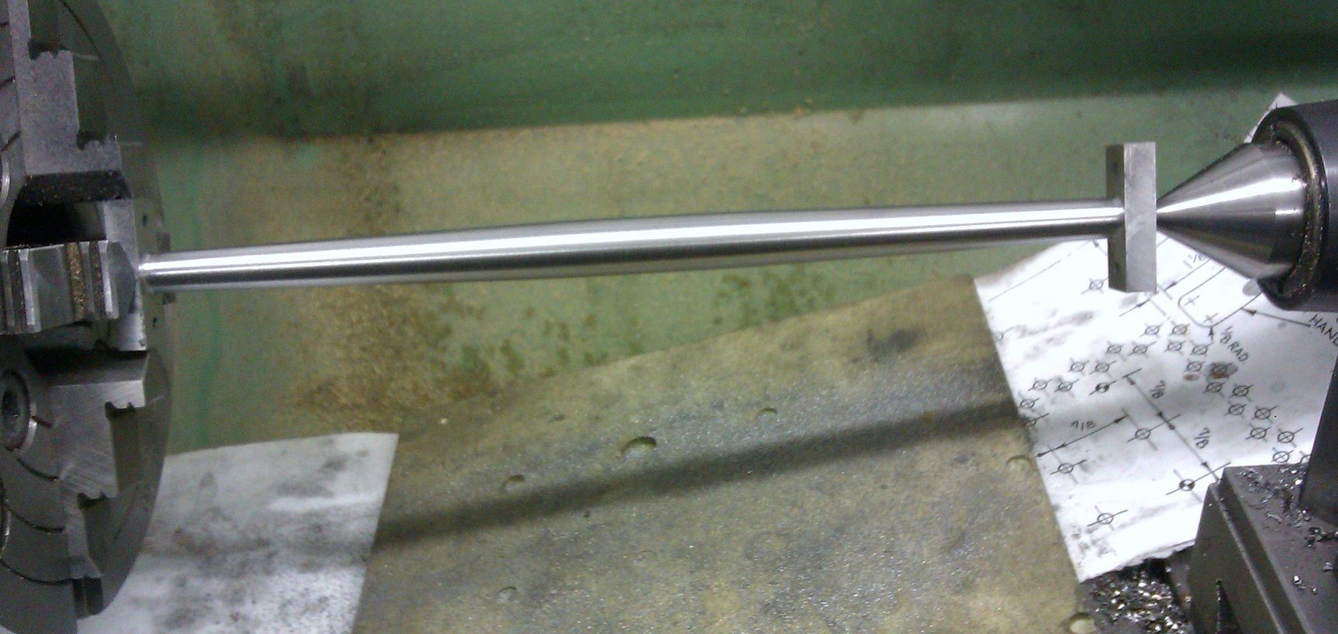
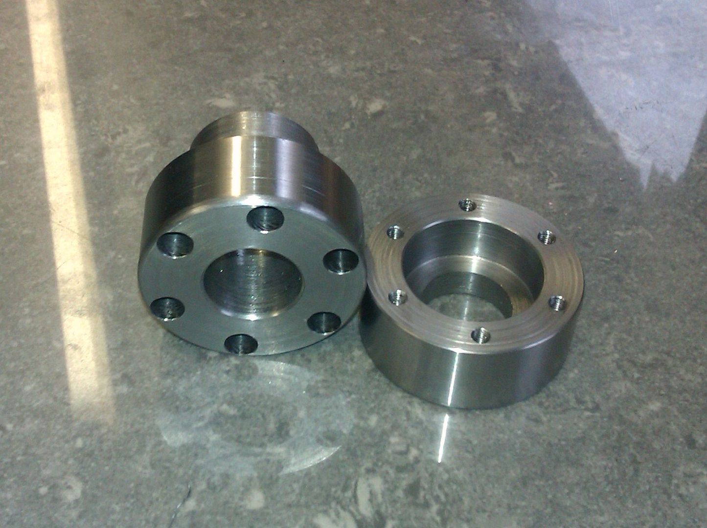
The two piece hub was a simple turning job from 1.5" bar with the same M3 holes added.

IMAG1255.jpg


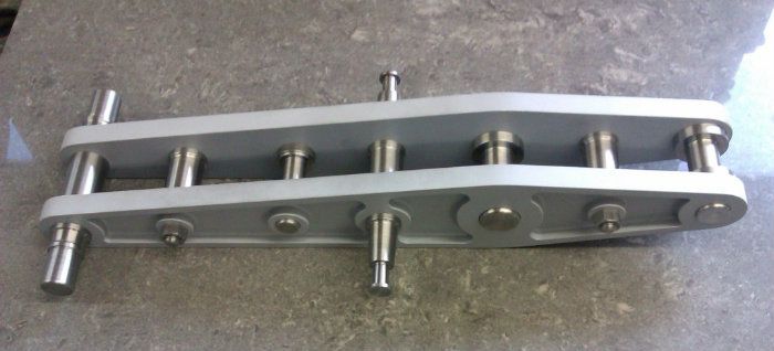
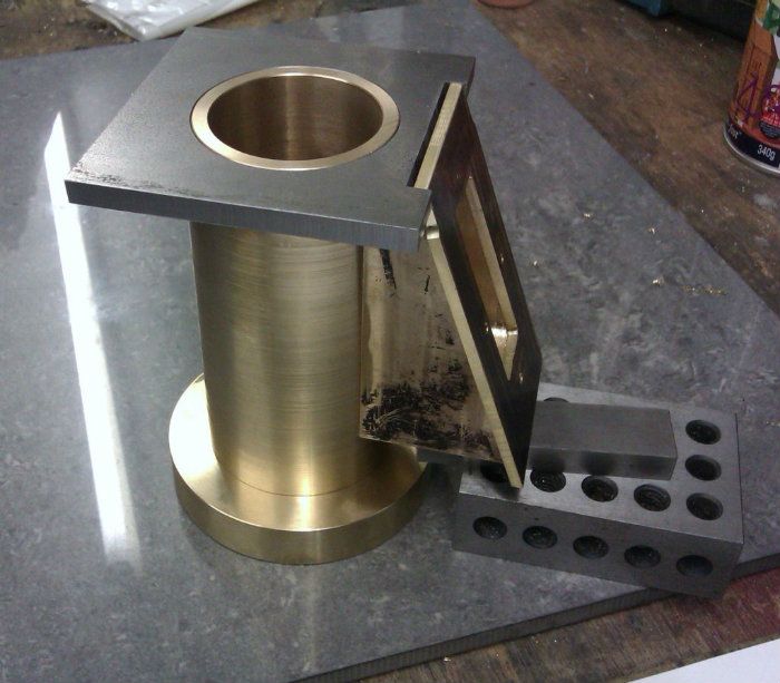
The parts were then all degreased and the rim put together with a smear of slow set Araldite adhesive, the hub with loctite. Here you can see things starting to take shape

IMAG1252.jpg


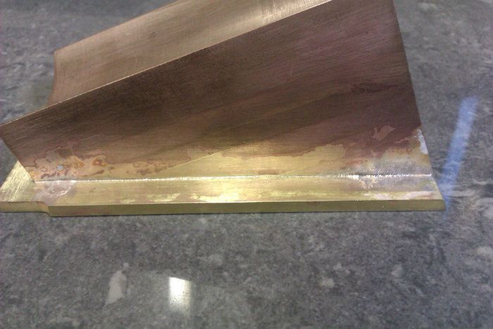
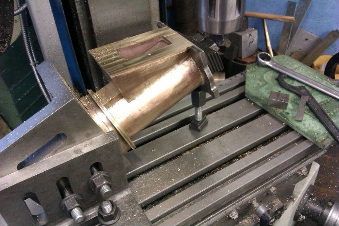
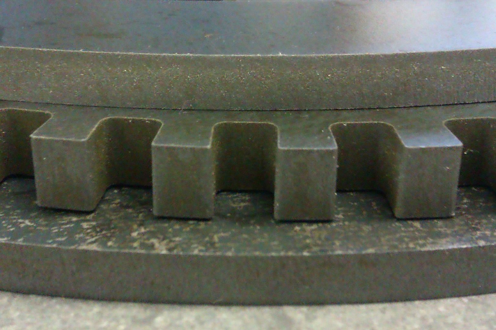
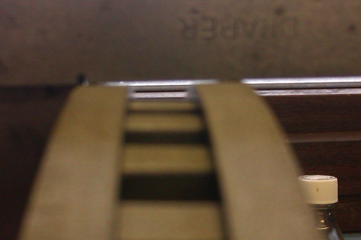
And a detail across the rim edge which just shows the "draft" angle left by the waterjet cutter.

IMAG1249.jpg


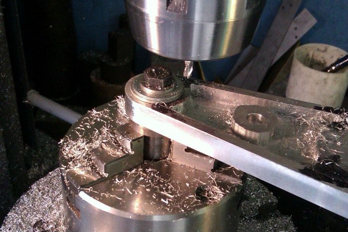
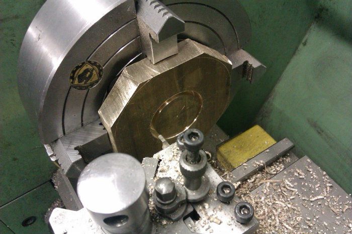
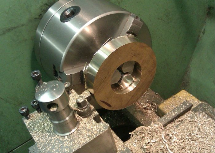
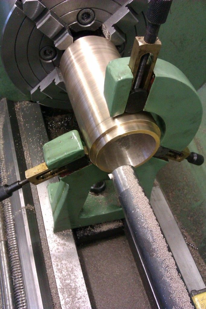
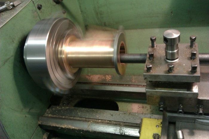
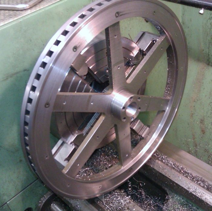
After the adhesive had been left for a day or two to set the flywheel was mounted on the lathe, luckily it could just be held by my 160mm 4-jaw. I was then just a case of taking the lightest skim off the rim to true things up, turn the side of teh ring to give a slight step and take 1.5mm off the sides of the spokes to get them down to 5mm overall.

IMAG1258_zpsed0d62d9.jpg


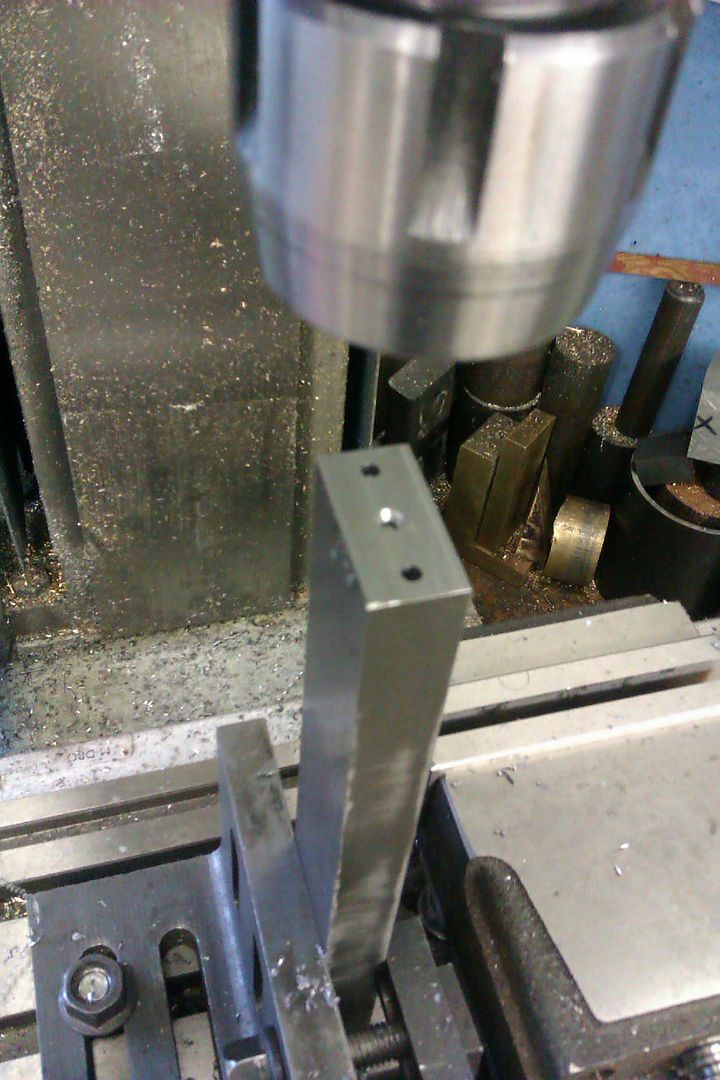
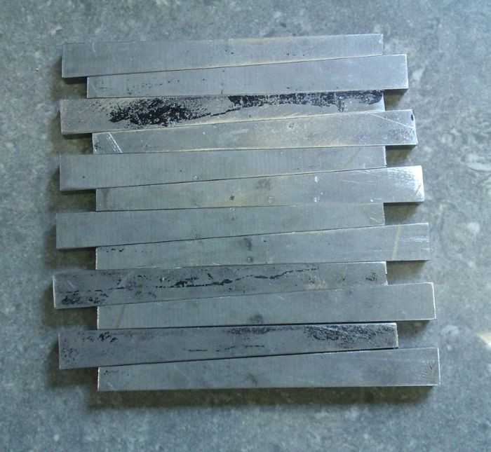
Next I turned my attention to the spoke webs, I had got a quote to have these water jet cut as well bit it was a bit pricy so I just cut them from 5mm plate with the hacksaw and cleaned them up on the mill.

IMAG1261_zps0eafb764.jpg


Two holes were drilled and Csk in each following which a bit of 1/8" welding rod was passed through the holes before being snipped off.

IMAG1262_zps89327078.jpg


These rod ends were then peined over like a rivit and the webs were not going anywhere.

c474a8a0-f8f7-4330-ace6-19a73ba46aa2_zps17f0feaa.jpg


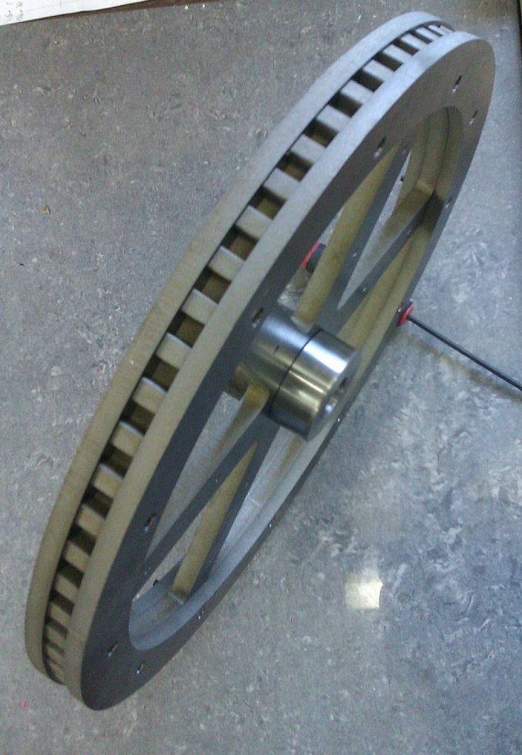
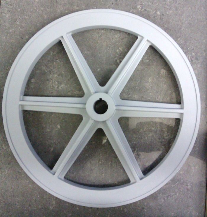
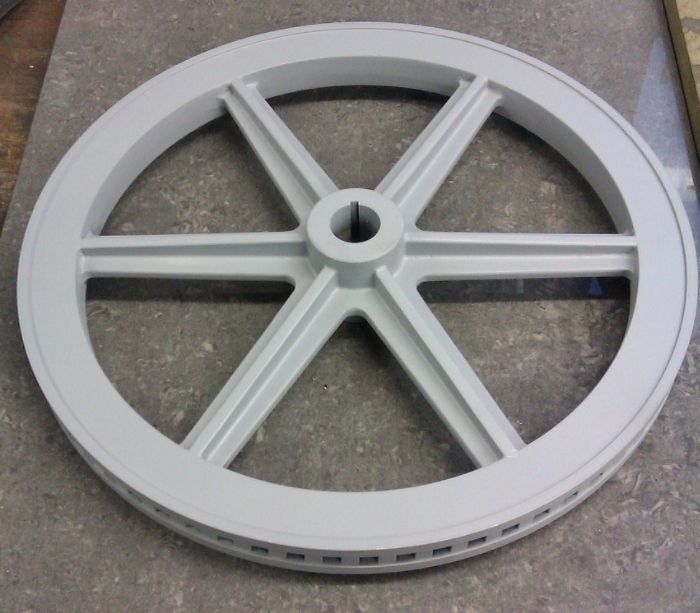
The final job was to fillet all the internal corners with Milliput and then give the flywheel a quick blast of primer.

IMAG1276_zps03beb5a2.jpg


IMAG1278_zpsb9cc1c2a.jpg


J
 
This is my favourite thread on this site, jumped up when i got the email to say you had made a new entry!
 

Latest posts

Back
Top